ICESat (Ice, Cloud and Land Elevation Satellite)
EO
Lidars
Atmosphere
Cloud type, amount and cloud top temperature
Quick facts
Overview
| Mission type | EO |
| Agency | NASA |
| Mission status | Mission complete |
| Launch date | 12 Jan 2003 |
| End of life date | 14 Aug 2010 |
| Measurement domain | Atmosphere, Land, Snow & Ice |
| Measurement category | Cloud type, amount and cloud top temperature, Cloud particle properties and profile, Aerosols, Landscape topography, Sea ice cover, edge and thickness, Ice sheet topography |
| Measurement detailed | Cloud optical depth, Cloud type, Aerosol Extinction / Backscatter (column/profile), Land surface topography, Sea-ice thickness, Sea-ice sheet topography |
| Instruments | GLAS |
| Instrument type | Lidars |
| CEOS EO Handbook | See ICESat (Ice, Cloud and Land Elevation Satellite) summary |
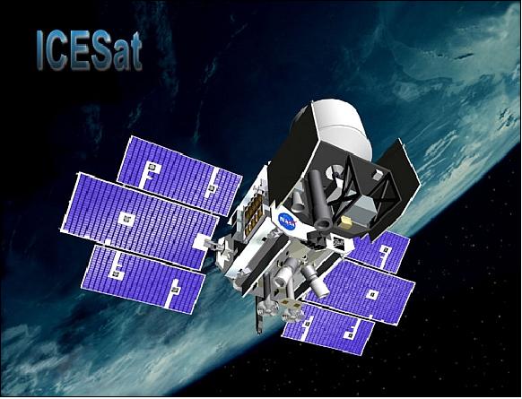
ICESat (Ice, Cloud and Land Elevation Satellite)
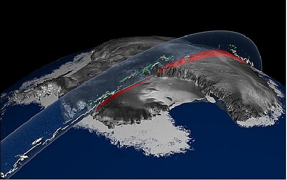
ICESat is a NASA/GSFC mission within the ESE (Earth Science Enterprise) program. The prime objective is to monitor the mass balance of the polar ice sheets and their contributions to global sea level change. Secondary goals are to measure cloud heights and the vertical structure of clouds and aerosols in the atmosphere, further to measure roughness, reflectivity, vegetation heights, snow-cover, and sea-ice surface characteristics, and to map topography of land surfaces. Note: ICESat is the renamed former “Laser Altimetry-1” mission. 1) 2) 3) 4) 5) 6)
Spacecraft
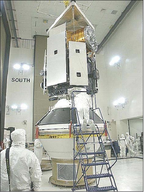
The mission has been developed in a partnership of NASA, industry, and university teams. The S/C integrator is BATC (Ball Aerospace and Technologies Corp.) of Boulder, CO. The ICESat structure is three-axis stabilized and is based on the BCP 2000 (Ball Commercial Platform 2000) series. The S/C configuration uses a simple panel-post aluminum honeycomb structure. The command and data handling subsystem consists of a S/C Control Computer (SCC), a Command and Telemetry Unit (CTU) and two Solid State Recorders (SSR) with a capacity of 56 Gbit (redundancy).
The attitude determination and control subsystem (ADCS) uses two star trackers, redundant IRUs (Inertial Reference Units), sun sensors and magnetometers for attitude determination. The pointing accuracy is 100 mrad per axis (1 sigma), the pointing knowledge is 50 mrad per axis (1 sigma), and the pointing stability is 10 µrad/s. The geolocation knowledge is < 15 m (3 sigma) after ground processing (use of 2 BlackJack GPS receivers). Four, low-vibration reaction wheels, and three torque rods with redundant windings and drivers are used for control. The electrical power and distribution subsystem employs a fully redundant power control unit, a 40 Ah NiH2 battery with a spare cell, two 3.2 m single-axis drive solar array panels, and distribution electronics. The S/C design life is 3 years with a goal of 5 years. Spacecraft mass = 970 kg (wet), payload mass = 298 kg. S/C power = 730 W (orbital average) with 350 W for payload operations. The S/C bus permits off-nadir pointing of up to 5º. A hydrazine propulsion system is used for orbit maintenance.
Mission Modes
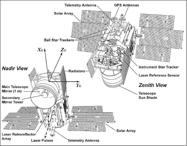
The normal attitude orientation of ICESat can be described with the axes shown in Figure 2. The -ZG axis is 0.3º from geodetic nadir (i.e., perpendicular to the Earth ellipsoid). Two basic ICESat orientations (attitude) are used to take best advantage of the sun geometry. In the sailboat (SB) mode, the YG axis (plus or minus) is closely coincident with the satellite velocity vector. In the airplane (AP) mode, the XG axis (plus or minus) is closely aligned with the velocity vector.
A specific attitude mode is used continuously for approximately six months. The 0.3º off-nadir angle is a fixed rotation of the spacecraft away from the Earth (a “pitch-up”) by this angle about an axis approximately perpendicular to the velocity vector to mitigate detector damage from specular reflections of laser pulses from mirror-like surfaces (e.g., still water).
The agile spacecraft allows special off-nadir pointing maneuvers to be performed that enable the laser to be pointed at a selected target of opportunity (TOO), which may lie slightly off the nominal nadir track, as well as to maintain pointing at the reference track to compensate for orbit drift. Pointing the laser at TOOs is commonly performed as a rotation about the axis perpendicular to the velocity vector (a “roll” maneuver). Such off-nadir pointing is allowed up to ±5º, i.e., to locations up to ±50 km away from the reference track.
In the polar regions (> 59º latitude in the Arctic, < -60º in the Antarctic), ICESat is commanded to always point at the reference track to compensate for natural orbit drift and enable near repeats (±100 m) of the tracks.
Launch
A launch of ICESat (along with ChipSat) on a Delta-2 vehicle from VAFB, CA took place on Jan. 13, 2003 (UTC).
RF Communications
Two separate, redundant X-band downlink transmitters and gimbaled antennas are provided for payload data. The SSR has direct links to the X-band downlink data transmitter. The X-band downlink data rate is 40 Mbit/s at a frequency of 8.100 GHz, modulation type PCM NRZ-M, SQPSK. The CCSDS protocol used is: version 2, grade 3, VCDU header and CRC. TT&C data can be transmitted in S-band or X-band at data rates of: 1, 4, 16 or 256 kbit/s. The uplink is in S-band at 2 kbit/s.
All ICESat flight operations activities are conducted at LASP (Laboratory for Atmospheric and Space Physics at the University of Colorado in Boulder) in the ICESat Mission Operations Control (IMOC). The ground network tracking stations (Poker Flat, AK, McMurdo, Antarctica, Svalbard, Norway, Wallops, VA) provide X-band capabilities for receiving science data dumps, S-band spacecraft data, real-time telemetry and commanding of the observatory. The NSDIC (National Snow and Ice Data Center) of the University of Colorado at Boulder is responsible for the archiving and distribution of ICESat science data to the science community at large. The University of Texas (UT) provides precision orbit and attitude information. 8)
Orbit
Near polar LEO orbit, altitude = 600 km, inclination = 94º, period = 101 minutes. Two primary orbits are used:
• Verification/validation orbit (90-120 days): this orbit has a ground track repeat cycle of 8 days to enable overflights of specific locations on the Earth which will be instrumented to support measurement verification or data product validation
• Mission orbit: this orbit has a ground track repeat cycle of 91 days to enable uniform sampling of the surface with high resolution.
Mission Status
• After seven years of service in orbit and 15 laser-operations campaigns, ICESat's science mission ended in February 2010 with the failure of its primary instrument.
While the GLAS instrument failed, the spacecraft itself remained in operating condition, so NASA could fire its thrusters to lower its orbit. NASA lowered the orbit of the ICESAT spacecraft by a series of thruster burns conducted in the period June 23-July 14, 2010 to deorbit the spacecraft. The orbit was reduced to an altitude of 200 km and then naturally decayed; but the final maneuvering was controlled by a group of students from the University of Colorado, working at the school’s Laboratory for Atmospheric and Space Physics (LASP). They sent it successfully plummeting through Earth's atmosphere at just the right moment so that the satellite’s remains would land in the chilly – and uninhabited — seas north of Norway and Russia (Barents Sea). The atmospheric reentry occurred on August 30, 2010. 9) 10) 11) 12)
• As of October 11, 2009, Laser 2 of GLAS (Geoscience Laser Altimeter System) onboard the ICESat spacecraft, stopped emitting light pulses. Since this time, no new science data have been returned from the GLAS instrument (Ref. 2).
- A GLAS Anomaly Review Board has reviewed and assessed the situation and a series of attempts to restart Laser 2 has been initiated, to be followed by attempts on the other two lasers which stopped working earlier in the mission.
- In late 2009, all revival attempts were stopped and the ICESat mission operations were ended. With about 6 1/2 years of intermittent operations, the mission was well beyond its design life of 3 years. -- The ICESat-2 mission, under development at NASA, will not be launched before 2015. 13)
• In 2009, the ICESat spacecraft and its payload were operating “nominally” (in a campaign style mode). Overall the mission has clearly demonstrated the important applications for spaceborne lidar and created a unique data set form thousands of orbits with many research applications. 14) 15)
• In 2005, the ICESat mission, with a design life of 3 years, was given a mission extension of 2.5 years. 16)
• Up to the end of 2004, ICESat acquired science data during five periods of laser operation ranging from 33 to 54 days each. ICESat's atmospheric measurements are providing fundamentally new information on the precise vertical structure of clouds and aerosols. In particular, cloud heights are important for understanding radiation balance and their effects on climate change. Other applications include mapping of polar sea-ice freeboard and thickness, high-resolution mapping of ocean eddies, glacier topography, and lake and river levels. 17)
• GLAS was activated on February 20, 2003, using laser 1. The initial measurement campaign was interrupted on March 29, 2003 by a failure of laser 1 (after 36 days of operation!!). An investigation team was formed and in August reported a problem with the pump laser diode arrays (LDA) within the laser transmitter subsystem as the source of the anomaly. This resulted in a modified operating plan, which called for approximately 30 day operation periods (campaigns), three times per year. The science measurement campaigns were replanned, and resumed in autumn 2003 using laser 2. 18) 19)
Laser campaign | Start date | End date | Orbit repeat days | S/C orientation |
1 | 2003-02-20 | 2003-03-21 | 8 | SB (sailboat mode) |
1a | 2003-03-21 | 2003-03-29 | 8 | AP (airplane mode) |
2a | 2003-09-25 | 2003-10-04 | 8 | SB |
2a | 2003-10-04 | 2003-11-18 | 91/33+ | SB |
2bb | 2004-02-19 | 2004-03-21 | 91/33 | SB |
2c | 2004-05-18 | 2004-06-21 | 91/33 | AP |
3a | 2004-10-05 | 2004-11-08 | 91/33 | SB |
3b | 2005-02-17 | 2005-03-24 | 91/33 | SB |
3c | 2005-05-20 | 2005-06-23 | 91/33 | AP |
3d | 2005-10-21 | 2005-11-24 |
|
|
3e | 2006-02-22 | 2006-03-27 |
|
|
3f | 2006-05-24 | 2006-06-26 |
|
|
Legend of Table 1: SAM (Sun Acquisition Mode) for 13 hours starting 2003-03-26 (during which no usable data were collected)). bSAM for 11 hours starting 2004-02-19. The 2a in column 1 denotes the operation of Laser 2 during the operation period a.
• So far, the GLAS instrument has provided a new, precise and global view of the vertical dimension of the Earth surface and atmosphere. The altimeter range resolution is < 3 cm for flat surfaces. Even with clouds, the altimetry surface measurement probabilities over the polar regions are > 50%. Although the GLAS duty cycle was reduced from 100% to 27% per year after problems with the lasers were found, Laser 3's 1064 nm performance shows promise for another 6 campaigns. The ICESat mission has already established a pathfinder set of measurements, which will enable an accurate and longer time series with the remaining ICESat measurements and with future missions. 21)
Sensor Complement
GLAS (Geoscience Laser Altimeter System)
GLAS is a NASA/GSFC instrument (Science team leader: B. E. Schutz, University of Texas at Austin). GLAS is a descoped version of the former GLRS (Geoscience Laser Ranging System). Objective: GLAS measures ice sheet topography, cloud heights, planetary boundary layer heights, and aerosol vertical structure. In addition, operation of GLAS over land and water provides along-track topography. 22)
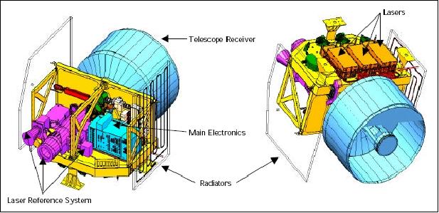
GLAS consists of a laser system to measure range, a GPS receiver, and a star-tracker attitude-determination system. The lasers are designated as Laser 1, 2, and 3, mounted on a rigid optical bench, with only one laser operating at a time.
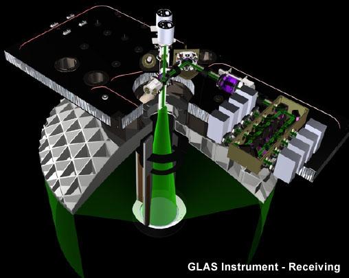
The laser transmits short pulses (4 ns) of infrared light (at 1064 nm) and visible green light (at 532 nm). The instrument is a nadir-viewing frequency-doubled, Q-switched, solid-state Nd:YAG laser. Each (of the three identical) lasers is a diode pumped Q-switched, solid-state Nd:YAG laser with energy levels of 75 mJ (1064 nm) and 35 mJ (532 nm). The pulse repetition rate is 40 pulses/s, and the beam divergence is approximately 0.1 mrad. The infrared pulse is used for surface altimetry, the green pulse is used for atmospheric measurements. The height measurements are determined from the round-trip pulse time. 23) 24)
The etalon filter is used in tandem with a 326 pm bandpass interference filter to provide a tunable bandpass filter over the entire etalon free spectral range (FSR) to accommodate variations among each (of the three) laser's wavelength and changes in any individual laser wavelength over the entire mission lifetime (3-5 years). This filter system, in conjunction with several single photon counting detectors, enables GLAS to provide lidar observations of cloud heights, bases, cloud optical properties, planetary boundary layer heights, lifting condensation levels, troposphere and stratospheric aerosols, and polar stratospheric clouds. 25)
Instrument mass = 298 kg, power = 330 W average, duty cycle = 100%, data rate = 450 bit/s, thermal control by radiators supplemented by heaters, heat pipes, thermal operating range: 20º ± 5º C, FOV of telescope = 375 µrad (nadir view only), FOV of instrument = 66 m laser footprint at nadir at 1064 nm, telescope size = 100 cm in diameter (height = 1.75 m).
Parameters or constituents measured | Cloud and aerosol data (extracted from 532 nm laser pulse) |
Laser type and transmitter wavelength | Nd:YAG laser with 1064 and 532 nm wavelength, a nadir-viewing frequency-doubled, Q-switched, solid-state Nd:YAG laser |
PRF (Pulse Repetition Frequency) | 40 Hz |
Laser energy/pulse | 75 mJ for 1064 nm and 35 mJ for 532 nm |
Pointing requirements (platform+instrument):
• Control (3 sigma): 30 arcsec roll, 60 arcsec pitch, 1º yaw
• Post-processed pointing knowledge (1-sigma): 1.5 arcsec (roll and pitch axes, provided by instrument-mounted star trackers laser reference sensor).
At 40 pulses per second, the centers of 66 m diameter footprints are separated in the along track direction by 170 m for a 600 km altitude orbit; cross track resolution is determined by the 183 day ground track repeat cycle which yields 15 km track spacing at the equator and 2.5 km at 80º latitude.
A small portion of the outgoing laser energy is used for instrument pointing. The extracted energy is input into two CCD cameras: LRS (Laser Reference Sensor) and LPA (Laser Profiling Array). The laser image in the LRS is formed at 10 Hz while the LPA uses the 40 Hz PRF of the instrument. A FOV of 0.5º x 0.5º of stars in the zenith direction is used in LRS. Thus, the LRS provides a combined image of the transmitted laser pulse superimposed on the star background. 26) A third CCD camera, mounted on the GLAS optical bench, is IST (Instrument Star Tracker) at 10 Hz and a FOV of 8º x 8º. IST is used for the spatial orientation of the optical bench with respect to the stars referred to as CRF (Celestial Reference Frame). The LPA provides a shot-by-shot record of the laser far field pattern and the beam direction with respect to to the optical bench; the LRS provides a calibration link between the CRF and the optical bench. The system provides a laser pointing accuracy of 1.5 arcsec (knowledge).
GLAS instrument Calibration
Special maneuvers are performed to support calibration/validation by rotating the satellite so as to scan a cone of 5º aperture about the nadir vector. These SMC (Scan Maneuver Calibrations) are conducted twice per day over the Pacific and approximately weekly over an entire orbital revolution (round-the-world scan). The SPE (Systematic Pointing Errors) of ICESat (orbital variation and bias trend) have been calibrated for each laser operations period with sub-arcsecond precision. 27)
GPS Receiver
The ICESat GPS receiver system is a spinoff of the BlackJack dual-frequency receiver developed by NASA/JPL for satellite-based science applications as flown on Jason-1. BlackJack is being used as a science instrument capable of providing dual-frequency GPS measurements that are being used for precise orbit determination. This allows the post-processing of the pseudorange and carrier phase recorded by BlackJack support the determination of the radial component of the of the GLAS position to an accuracy of about 2-3 cm rms. 28)
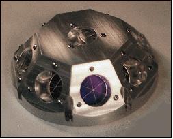
RRA (RetroReflector Array)
RRA consists of 9 corner cube reflectors for SLR (Satellite Laser Ranging) support. The corner cubes are made of research grade radiation resistant suprasil quartz. Their performance is optimized at the green wavelength of 532 nm. The corner cubes are symmetrically mounted on a hemispherical surface with one nadir-looking corner cube in the center, surrounded by an angled ring of eight corner cubes.
The ground-based SLR network provides data to support POD (Precise Orbit Determination) and the use of navigation data collected by the onboard BlackJack GPS receiver.
References
1) B. E. Schutz, “Spaceborne Laser Altimetry: 2001 and Beyond,” published in: H. P. Plag (ed.), 1998, Book of Extended Abstracts, Wegener-98, Norwegian Mapping Authority, Honefas, Norway
2) http://icesat.gsfc.nasa.gov/
3) https://web.archive.org/web/20240225072111/http://www.csr.utexas.edu/glas/
4) B. E. Schutz, H. J. Zwally, C. A. Shuman, D. Hancock, J. P. DiMarzio, “Overview of the ICESat Mission,” Geophysical Research Letters, Vol. 32, Nov. 2005, L21S01, doi:10.1029/2005GL024009
5) http://science.hq.nasa.gov/missions/satellite_20.htm
6) http://eospso.gsfc.nasa.gov/eos_homepage/mission_profiles/docs/ICESat.pdf
7) Bob E. Schutz, H. Jay Zwally, “ICESat Overview,” 16th International Workshop on Laser Ranging, Poznan, Poland, October 13-17, 2008, URL: http://cddis.gsfc.nasa.gov/lw16/docs/presentations/sci_5_Schutz.pdf
8) C. Webb, T. Urban, B. Schutz, “ICESat/GLAS CSR SCF Release Notes for Orbit and Attitude Determination,” Aug. 2006, URL: http://nsidc.colorado.edu/data/icesat/pdf_files/CSR_SCF_Release_Notes.pdf
9) http://icesat.gsfc.nasa.gov/icesat/faq.php
10) “Ice Cloud And Land Elevation Mission Comes To An End,” Space Daily, Aug. 31,2010, URL: http://www.spacedaily.com/reports/Ice_Cloud_And_Land_Elevation_Mission_Comes_To_An_End_999.html
11) “Students Send ICESat to a Fiery Deorbit Death,” Universe Today, Sept. 2, 2010, URL: http://www.universetoday.com/72526/students-send-icesat-to-a-fiery-deorbit-death/
12) “Groundbreaking NASA satellite mission comes to a finale,” NSIDC, August 30, 2010, URL: http://nsidc.org/news/press/20100830_icesat.html
13) Debra Werner, “NASA Budget for Earth Science Lags Behind Rising Expectations,” Space News, January 4, 2010, p. 1
14) Information provided by Kristine Barbieri of NASA/GSFC
15) B. Ionnotta, “Program Managers Ask NASA to extend ICESat Mission,” Space News, April 9, 2007, p. 46
16) http://lasp.colorado.edu/news/2005/quickscat_icesat_sept.htm
17) H. Zwally, “Overview of the ICESat Mission and Results,” AGU Fall Meeting 2004, San Francisco, CA, Dec. 13-17, 2004
18) R. A. Kichak, (2003), “Independent GLAS Anomaly Review Board Executive Summary,” report, Goddard Space Flight Cent., Greenbelt, MD, URL: https://web.archive.org/web/20140403235755/http://misspiggy.gsfc.nasa.gov/tva/meldoc/photonicsdocs/IGARBreport.pdf
19) D. M. Tratt, F. Amzajerdian, N. B. Kashem, M. A. Stephen, A. A. Shapiro, A. T. Mense, “Promoting Robust Design of Diode Lasers for Space: A National Initiative,” Proceedings of the 2008 IEEE Aerospace Conference, Big Sky, MT, USA, March 1-8, 2008, paper: 5.0201
20) https://web.archive.org/web/20050218002057/http://www.nsidc.com/data/icesat/data.html
21) J. B. Abshire, X. Sun, H. Riris, J. M. Sirota, J. F. McGarry, S. Palm, D. Yi, P. Liiva, “Geoscience Laser Altimeter System (GLAS) on the ICESat Mission: On-orbit measurement performance,” Geophysical Research Letters, Vol. 32, Nov. 2005, L21S02, doi:10.1029/2005GL024028
22) J. B. Abshire, X. Sun, H. Riris, M. Sirota, J. McGarry, S. Palm, D. Yi, P. Liiva, “Geoscience Laser Altimeter System (GLAS) on the ICESat Mission: On-orbit measurement performance,” Proceedings of the Sixth Annual NASA Earth Science Technology Conference (ESTC 2006), College Park, MD, USA, June 27-29, 2006, URL: https://web.archive.org/web/20240911094115/http://www.esto.nasa.gov/conferences/ESTC2006/papers/b1p4.pdf
23) “GLAS Geoscience Laser Altimeter System,” ESE Reference Handbook, 1999, NASA/GSFC, pp. 113-114
24) B. E. Schutz, “Laser Altimetry and Lidar From ICESat/GLAS,” IGARSS 2001, Sydney, Australia, July 9-13, 2001
25) M. A. Krainak, M. A. Stephen, A. J. Martino, D. L. Lunt, “Tunable solid-etalon filter for the ICESat/GLAS 532 nm channel lidar receiver,” Proceedings of IGARSS 2003, Toulouse, France, July 21-25, 2003
26) L. .A. Magruder, B. E. Schutz, E. C. Silverberg, “Pointing Angle and Timing Calibration/Validation of the Geoscience Laser Altimeter with a Ground-Based Detection System,” IGARSS 2001, Sydney, Australia, July 9-13, 2001
27) S. B. Luthcke, D. D. Rowlands, T. A. Williams, M. Sirota, “Reduction of ICESat systematic geolocation errors and the impact on ice sheet elevation change detection,” Geophysical Research Letters, Vol. 32, Nov. 2005, L21S05, doi:10.1029/2005GL023689
28) J. Williams, E. G. Lightsey, S. P. Yoon, R. E. Schutz, “Testing of the ICESat BlackJack GPS Receiver Engineering Model,” ION-GPS 2002, Portland, OR, Sept. 24-27, 2002