CryoSat (Earth Explorer Opportunity Mission-1)
EO
ESA
Ocean
Mission complete
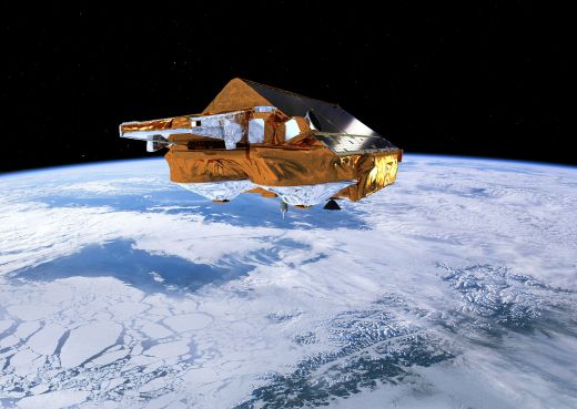
Launched in October 2005, CryoSat was a next-generation radar altimetry mission, aiming to observe the polar regions.CryoSat was supposed to be the first Earth Explorer Opportunity mission in ESA’s Living Planet program, but was lost in a launch failure on 8 October 2005, prompting the development of a successor mission, CryoSat-2.
Quick facts
Overview
| Mission type | EO |
| Agency | ESA |
| Mission status | Mission complete |
| Launch date | 08 Oct 2005 |
| End of life date | 08 Oct 2005 |
| Measurement domain | Ocean, Land, Gravity and Magnetic Fields, Snow & Ice |
| Measurement category | Gravity, Magnetic and Geodynamic measurements, Landscape topography, Ocean topography/currents, Sea ice cover, edge and thickness, Ice sheet topography |
| Measurement detailed | Land surface topography, Sea-ice thickness, Geoid, Sea level, Sea-ice sheet topography, Gravity field |
| Instruments | DORIS-NG, Laser Reflectors (ESA), SIRAL |
| Instrument type | Precision orbit, Radar altimeters |
| CEOS EO Handbook | See CryoSat (Earth Explorer Opportunity Mission-1) summary |
Related Resources
Summary
Mission Capabilities
The CryoSat sensor complement consisted of three instruments. The Synthetic Aperture Radar (SAR) Interferometer Radar Altimeter (SIRAL) was a Ku-band radar altimeter which aimed to make observations of ice sheet interiors and margins, for sea ice and topographical calculations. The satellite also carried the Doppler Orbitography and Radio Positioning Integration by Satellite (DORIS) instrument, which was supposed to measure the Doppler frequency shifts of both VHF and S-Band signals transmitted by ground beacons to allow precise orbit determination, as well as a Laser Retroreflector (LRR), a passive optical sensor that was to be used as a secondary method of orbit determination.
Performance Specifications
SIRAL used a frequency of 13.575 GHz, with a pulse bandwidth of 320 MHz and a pulse duration of 50 µs. It had an antenna footprint of 15 km, with a range resolution of approximately 0.45 m and along-track resolution of 250 m. SIRAL operated in three distinct modes, low resolution mode (LRM), used in conventional pulse-limited operation for ice sheet interiors and open oceans, Synthetic Aperture Radar (SAR) mode, used to enhance the accuracy of measurements of sea ice, and SAR Interferometric (SARIn) mode, which provided improved elevation estimates over variable topography. The DORIS onboard receiver measured the Doppler shift of ground-based uplink beacons in two frequencies - 2.03625 GHz for Doppler measurement and 401.25 MHz for ionospheric correction. It was capable of precise orbit determination with an accuracy of 0.2 m - 0.6 m. LRR had a field of view (FOV) of ±57.6°, with predicted target error below 6 mm.
CryoSat was planned for operation in an inclined, non-sun-synchronous orbit, with an altitude of 717 km, an orbit inclination of 92°, and a repeat cycle of 369 days.
Space and Hardware Components
The CryoSat bus was manufactured by EADS Astrium, a subsidiary of the European Aeronautic Defence and Space Company (EADS), with dimensions 4.6 m x 2.34 m x 2.20 m, and an approximate weight of 670 kg. It had a design life of three and a half years, with power generation provided by two triple-junction Gallium Arsenide (GaAs) solar arrays. CryoSat would have usedS-band for all Tracking Telemetry and Command (TT&C) communication, with payload data downlinked in X-band, at a rate of 100 Mbit/s.
CryoSat (Earth Explorer Opportunity Mission-1)
Overview
CryoSat is the first Earth Explorer Opportunity Mission in ESA's Living Planet Program; it is a next-generation radar altimetry mission dedicated to observations of the polar regions. The science objectives are to determine variations in the thickness of Arctic sea ice and elevation changes of ice sheets, ice caps and glaciers that ring the Arctic Ocean (continental ice sheets). Sea ice plays a central role in Arctic climate. The CryoSat mission is to further knowledge of the wider role of the Earth's cryosphere and its effect on the sea level. The CryoSat mission was proposed by Duncan Wingham of the University College London (UCL) and an international science team. Duncan Wingham is also the mission PI. A nominal mission duration of three years is planned (excluding the commissioning and validation phases, which may last up to six months). 1) 2) 3) 4) 5) 6) 7) 8) 9)
Spacecraft
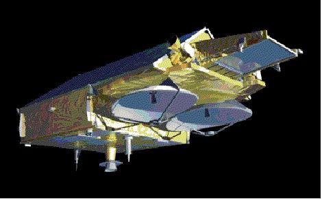
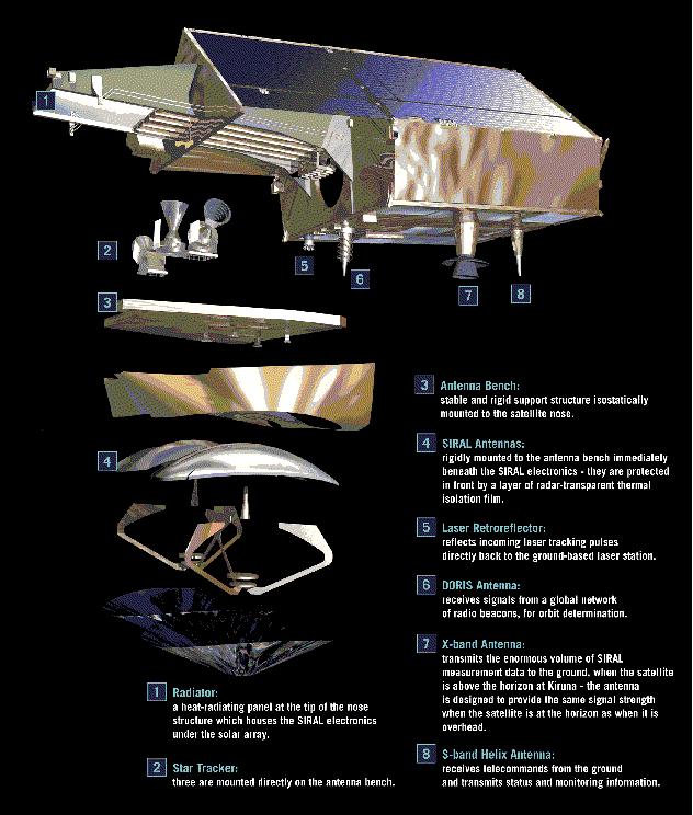
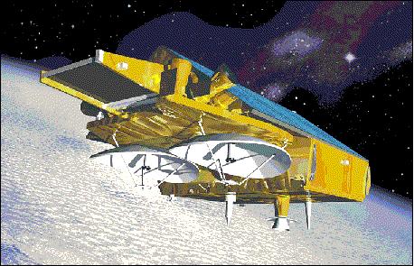
The CryoSat spacecraft is being built and integrated by EADS Astrium GmbH of Friedrichshafen, Germany, as prime contractor. The spacecraft structure consists of a long rectangular main platform body, surmounted by fixed solar arrays in the form of a tent. The spacecraft has neither deployable appendages nor any other moving parts except for thruster valves. The lower surface of this structure is permanently earth facing. All electronics are mounted on the nadir plate acting as radiator. The antennas used for radio communication, and the Laser Retroreflector, are mounted on this surface; an emergency antenna for command and monitoring is also fitted on top of the satellite between the solar arrays. The two SIRAL instrument antenna dishes are mounted on a separate rigid bench in the forward section of the S/C. In addition, a dedicated SIRAL radiator is mounted at the nose tip.
The S/C is 3-axis stabilized. A slight nose-down attitude of the S/C (6º) is chosen (using magnetorquers and 10 mN cold-gas thrusters) to ensure minimum attitude correction due to gravity-gradient disturbances. The S/C has dimensions of 4.6 m x 2.34 m x 2.20 m. The S/C mass is about 670 kg (including 36 kg propellant), the design life is 3.5 years. S/C Power generation is provided by two triple-junction GaAs solar arrays with an efficiency of >25% (two oriented solar panels), each panel provides power of 800 W at normal solar incidence. The energy is stored by a lithium-ion battery (60 Ah capacity).
The pointing requirements are the main design drivers for the AOCS: 10)
· High precision cross-track pointing knowledge of < 10 arcsec for SARIn mode (SARIn refers to the SAR interferometric mode).
· S/C attitude maintenance with a pointing accuracy of < 0.2º per axis and a pointing stability of < 0.005º for 0.5 s in the nominal Earth-pointing phase of the mission
· Provision of very low disturbances due to thruster activity to meet the very high precise orbit determination (POD) accuracy of the CryoSat orbit.
The AOCS (Attitude Orbit and Control Subsystem) comprises the following elements:
· A cold gas system (RCS) for attitude control and orbit transfer and maintenance maneuvers, 16 attitude control thrusters (10 mN) and 4 orbit control thrusters (40 mN). Nitrogen is used as propellant (132 l tank).
· A set of 3 magnetorquers is used for compensation of environmental disturbance torques in support of RCS. The MT30-2-GRC, originally developed and qualified for the GRACE mission by ZARM Technik GmbH, has been selected for CryoSat.
· A set of three star tracker heads (also a part of the payload) providing autonomous inertial attitude determination for the spacecraft. The multiple configuration makes the sensor system one-failure tolerant, except for the rare occurrence of simultaneous sun and moon blinding of two heads, to which the system software is tolerant. Consequently, two camera heads are operated in parallel at all times to cope with sun-blinding. In its acquisition mode, which takes 2-3 seconds, the star tracker calculates a coarse attitude by matching triangle patterns of stars with patterns stored in its catalog. Subsequently, in attitude update mode it calculates precise attitude at a rate of 1.7 Hz.
The star tracker attitude serves also as reference for determining the orientation of the SIRAL interferometric baseline. The orientation of the interferometric baseline needs to be very accurately measured in-flight: small errors in knowledge of the roll-angle translate into substantial errors in the elevation of off-nadir points. The HE-5AS star tracker of Terma A/S, originally developed and qualified for the NEMO (Navy EarthMap Observer) and FCT (Foreign Comparative Test) projects, is selected for CryoSat. It is a fully autonomous star tracker capable of delivering high-accuracy inertial attitude measurements from a lost-in-space condition with no external attitude information. The EOL performance of the star tracker is < 3.2 arcsec in the lateral axes and < 16 arcsec about the roll axis under worst-case conditions.
The star tracker baffle has been designed to meet the required sun exclusion angle of 30º and the moon exclusion angle of 25º. These exclusion angles ensure together with the star tracker accommodation on the antenna bench that during the whole mission sun and moon can only blind one star tracker head at any time.
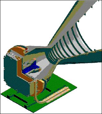
· A DORIS receiver is part of an overall system, for real-time measurements of satellite position, velocity and time. DORIS measures the Doppler frequency shifts of VHF and S-band signals transmitted by ground beacons. Its measurement accuracy is < 0.5 mm/s in radial velocity allowing an absolute determination of the orbit position with an accuracy of 2-6 cm (see DORIS and LLR description under sensor complement). - The DORIS system comprises a network of more than 50 ground beacons, a number of receivers on several satellites in orbit and in development, and ground segment facilities. It is part of the International DORIS Service, the IDS, which also offers the possibility of precise localization of user beacons.
· CESS (Coarse Earth-Sun Sensor) of CHAMP and GRACE heritage (a patented design of Astrium GmbH). Provides attitude measurements (<5º) with respect to the sun and Earth for initial acquisition and coarse pointing. The FOV of CESS is a full spherical one, i.e. no special search maneuvers are necessary to find the Earth or the sun. Its measurement principle is based The concept is based on temperature differences measured by 6 omnidirectional arranged sensor heads (PT1000 thermistors).
· A set of three three-axis fluxgate magnetometers are used for magnetorquer control and as rate sensors. They provide a measurement range of at least ± 60.000 nT with an accuracy of better than 0.5 % full scale.
The AOCS provides high pointing accuracy (a few tens of an arcsecond), knowledge and stability in nominal Earth-pointing. It also has to perform the orbit changes between the science and validation phase orbits. The AOCS uses inertial attitude measurements from the set of 3 star tracker camera head units and DORIS real-time navigation to convert the inertial attitude into Earth referenced attitude (star sensor FOV of 22º x 22º, ). - The RCS (Reaction Control Subsystem), developed at PolyFlex Space Ltd. (a Marotta UK Ltd. company), is a cold gas propulsion system for auxiliary attitude control (in which it provides deadband protection around the axis defined by the instantaneous geomagnetic field) and for orbit transfer and maintenance manoeuvres. It has 16 attitude control thrusters of 10 mN each and 4 orbit control thrusters of nominally 40 mN each. A single high-pressure tank stores 36.2 kg of nitrogen gas at 278.6 bar. 11)
The CDMU (Control and Data Management Unit), consisting of a processor and a hardware- based fault detection system, handles all on-board command and control functions including telecommand decoding and the AOCS processing functions (the OBC is based on the ERC-32 microprocessor). A MIL-STD-1553B communications bus is used as payload interface (for SIRAL and DORIS). The on-board solid-state memory has a capacity of 2 x 128 Gbit.
Launch
The launch of CryoSat took place on Oct. 8 2005 using the launch vehicle Rockot-KM of Eurockot from Plesetsk, Russia. The Rockot vehicle is being outfitted with a versatile, restartable upper stage, known as Breeze-KM, for final and accurate orbit injection. Unfortunately, the satellite did not attain orbit due to a failure of the final stage of the launch system resulting in a loss of the mission.
An investigation by the Russian Failure Investigation State Commission has determined that a flight control system in the Rockot's Breeze upper stage caused the loss of the ESA's Cryosat satellite. The failure occurred when the Breeze didn't generate the command to shut down the second stage's engines. A set of measures is now being implemented to prevent a re-occurrence of the incident. 12)
Satellite Orbit: Non sun-synchronous circular LEO orbit, mean altitude = 717 km, inclination =92º, nodal regression of 0.25º per day. Ground track repeat cycle: 369 days (with 30 day pseudo subcycles). This configuration allows a sufficient coverage for the polar regions. The CryoSat mission requirements include:
· An orbit change is required during the mission with the objective to visit at least twice a validation orbit, approximately 6 km lower in altitude than the science phase orbit
· The payload must be operated in various modes, as a function of geographical region, such that the orbital operations, and data sets collected, on successive orbits are dissimilar
· The payload utilization demands very precise orbit and attitude restitution. Minimum operations of three years are required.
The CryoSat mission is aimed in part at gaining coincident coverage with the GLAS laser altimeter of the NASA ICESat mission. The following support phases are defined:
· Commissioning phase: The nominal duration is two months. During this phase the satellite and its payload are brought into a fully operating condition in its nominal orbit.
· Science phase: This includes a long-repeat cycle \[a 369-day orbit (5344 revolutions) repeat phase will be used, with a 30-day subcycle\]. The science phase is the nominal operational support mode of the mission. This orbit is designed to provide very dense orbit cross-overs above 72º of latitude, for use over the ice sheets. With coverage to 88º of latitude, all but a very small area of the land and marine ice fields will be within the coverage of the satellite. In addition, the 30 day subcycle provides approximately monthly coverage of the sea ice fluctuations.
· Validation phases: The objective is to conduct calibration or validation experiments that are at a fixed locations on Earth. In these phases the satellite may be placed into a 2-day repeat orbit. A validation phase may have a duration of up to 1 month, and there may be more than one during the mission lifetime. The measurements made by the satellite mission will need to be verified by ground-based experiments.
RF communications: The S-band link is used for all TT&C communications (2 kbit/s uplink and 8 kbit/s downlink). The X-band downlink (center frequency of 8.100 GHz) provides a payload transfer rate of 100 Mbit/s. All onboard data are stored in the MMFU (Mass Memory and Formatting Unit) of 2 x 128 Gbit (EOL) capacity. Data arrive at the MMFU directly from the SIRAL instrument on a pair of fast IEEE 1355 standard serial links (for the two high-rate interferometric data channels) and via the MIL-STD-1553 bus for the low rate data channels. Data are also transferred from the CDMU and the DORIS over the MIL-STD-1553 bus. About 320 Gbit/day of onboard source data are being generated and transmitted to the ground.
Ground Segment
The CryoSat mission will be operated from ESA/ESOC, Darmstadt, Germany. The Kiruna ground station in Sweden functions as the prime command and data acquisition facility. The payload data segment (data processing, archiving and distribution) function is also located at the Kiruna station. The ground segment makes use of the existing infrastructure. All user interfaces are coordinated via ESA/ESRIN with dissemination of data from Kiruna.
Sensor Complement
SIRAL (SAR Inferometer Radar Altimeter)
SIRAL (SAR Interferometer Radar Altimeter) designed and developed for ESA by ASI (Alcatel Space Industries), France. SIRAL is of Poseidon-2 heritage flown on the Jason-1 mission. The objective is to observe ice sheet interiors, the ice sheet margins, for sea ice and other topography. The SIRAL design features two receiving antennas forming an interferometer in the cross-track direction with a baseline of 1.2 m (support for SARIn mode). In addition, the return signal in along-track direction is processed to construct a synthetic aperture for enhanced ground resolution. The instrument is a Ku-band radar altimeter which uses the full-deramp range compression technique of conventional altimeters (conventional single frequency pulse-limited altimeter). However, it introduces two features that make it different from previous spaceborne altimeter implementations: 13) 14) 15) 16)
1) The instrument has two parabolic antennas (including pulse-to-pulse phase coherence) and two receive chains, permitting an interferometric mode of operation (and interferometric signal processing).
2) SIRAL operates at high PRF (Pulse Repetition Frequency), ensuring coherent along-track sampling for aperture synthesis (PRF>Doppler bandwidth). The distinguishing feature of SIRAL compared to conventional altimeter instruments (generally with pulse intervals of about 500 µs) is that it sends bursts of pulses separated by intervals of only 50µs. Though the return echoes are correlated, the bursts are instead treated using "aperture synthesis" data processing techniques.
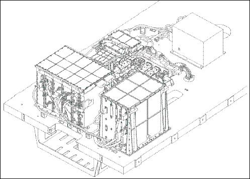
The instrument consists of three major subsystems, two of these are in discrete electronic boxes:
· DPU (Digital Processing Unit), it serves all digital altimeter functions, including the digital chirp generation, the full sequencing functions of the altimeter, and the receive and processing functions of the echo
· RFU (Radio Frequency Unit). It contains all analog IF and RF electronics and a solid-state power amplifier with an RF peak power of 25 W.
The antenna subsystem consists of two Cassegrain antennas, mounted side-by-side and forming the interferometric cross-track. Both antennas are identical; one is used to transmit and receive, whereas the other antenna is used to receive echoes (bistatic configuration). The primary super- elliptic reflectors are about 1.1 m x 1.2 m in size. They are supported by a composite sandwich plate. A high thermoelastic stability is needed to meet the interferometric instrument performance. The new features of SIRAL have been demonstrated with the airborne D2P (Delay-Doppler Phase-monopulse Radar) of JHU/APL.
Parameter | Value |
RF frequency | 13.575 GHz (single frequency Ku-band radar) |
Pulse bandwidth | 320 MHz, (40 MHz for tracking only in SARIn) |
PRF (Pulse Repetition Frequency) | 1.97 kHz in LRM, 17.8 kHz in SAR and in SARIn; coherent pulse transmission for Doppler processing |
Burst mode PRF | 1970 Hz in LRM, 85.7 Hz in SAR and 21.4 Hz in SARIn |
Pulse duration | 50 µs |
Timing | Regular PRF in LRM, burst mode in SAR/SARIn |
Samples/pulse | 128 in LRM and SAR, 512 in SARIn |
RF peak power | 25 W |
Antenna size | 2 reflectors 1.2 m x 1.1 m, side-by-side |
Antenna beamwidth (3 dB) | 1.08º (along-track) x 1.2º (cross-track) |
Antenna footprint | 15 km |
Range resolution | About 45 cm |
Along-track resolution | 250 m (SAR/SARIn) |
Data rate | 60 kbit/s for LRM, 12 Mbit/s in SAR, 2 x 12 Mbit/s in SARIn |
Instrument mass (with antennas) | 70 kg non-redundant |
Instrument power | 149 W |
The science requirements demand of CryoSat to measure variations in ice thickness of perennial sea and land ice fields to the limit allowed by natural variability, on spatial scales varying over three orders of magnitude. The natural variability of sea and land ice depends on fluctuations in the supply of mass by the atmosphere and ocean, and snow and ice density. The precisions of the measurements are expressed in terms of cm of yearly ice equivalent thickness variations. These are:
· Arctic sea-ice: 1.6 cm/year vertical measurement accuracy at 105 km2 scale (equivalent to 300 km x 300 km cells). Temporal sampling: 1 month
· Land ice (small scale): 3.3 cm/year at 104 km2 (equivalent to 100 km x 100 km cells). Temporal sampling : 1 year
· Land-ice (large scale): 0.17 cm/year over 13.8 x 10⁶ km2 (about the area of Antarctica). Temporal sampling: 1 year.
Parameter | Coverage area (km2) | Science requirement | Measurement accuracy |
Artic sea ice | 105 at or above 50º latitude | 3.5 cm/year | 1.6 cm/year |
Ice sheets | |||
Regional scale | 103 to 104 | 8.3 cm/year | 3.3 cm/year |
Antarctica | 106 | 0.76 cm/year | 0.17 cm/year |
The monitoring of the interferometric behavior of the receive chains is ensured by a dedicated interferometric calibration mode that can be used as an operational mode. An additional calibration mode permits the measurement of the amplitude/phase distortions of each receive chain. By using an internal frequency synthesizer, this measurement can be done for several frequencies inside the IF bandwidth. In addition, different gain settings can be used, which makes it possible to accurately determine the gain of the receiver. Either of the receive chain (chain 1 or 2) may be selected in LRM or in SAR support modes. This in-flight capability increases the knowledge of the instrument contribution on the echo measurement.
The chirp generator is composed of a digital pulse generation section, operating with a sampling rate of 160 MHz, followed by an analog multiplier section expanding the pulse bandwidth by a factor of 16, up to 350 MHz. This configuration ensures the pulse-to-pulse coherence required for the SAR modes. Parameters: chirp frequency = 4.08 GHz; bandwidth = 350 MHz; signal duration = 51 µs; SNR=30 dB.
The SSPA (Solid-State Power Amplifier) is composed of four parallel hybrid amplifiers in PHEMT technology. Parameters: frequency = 13.575 GHz; peak power >25 W; gain = 9 dB; amplitude ripple = 0.2 dB in 350 MHz; efficiency = 24%. - The FFT (Fast Fourier Transform) module, needed for the on-board tracking algorithm to estimate range and gain commands, makes use of the existing FFT module of POSEIDON 2.
SIRAL operations: SIRAL provides the following operational modes for different observational support types. The complex waveform data stream from the CryoSat altimeter requires a sophisticated processing scheme in particular for exploiting the synthetic aperture and interferometry techniques over ocean and ice surfaces.
· LRM (Low Resolution Mode) operation support: LRM uses a single receive channel and low PRF for conventional pulse-limited operation for ice sheet interiors/open oceans. The transmitted pulse length and the transmitted bandwidth are set to the same value as that for Envisat in a similar mode (51 s, 320 MHz). The PRF is kept constant over the orbit at a value around 2 kHz to ensure the decorrelation of received echoes. The averaging for tracking and ground processing is performed after the FFT (Fast Fourier Transform).
The LRM mode is useful over surfaces where the topography is homogeneous, at least as large as the antenna footprint of about 15 km. The altimeter echoes have a predictable shape and the mean surface level of this area can be derived by an appropriate model.
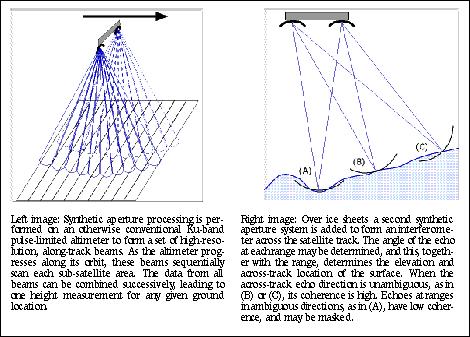
· SAR (Synthetic Aperture Radar) support mode: SAR uses a single channel and a high PRF. Closed burst timing is employed to ensure a high along-track resolution. The PRF is chosen higher than the Doppler bandwidth over the half-power beamwidth to avoid aliasing in the ground processing of the data (the PRF is about 10 times higher than that of LRM to ensure coherence between the echoes of successive pulses). Bursts of 64 pulses at a PRF of 18.5 kHz with a burst repetition frequency of 85 Hz are transmitted.
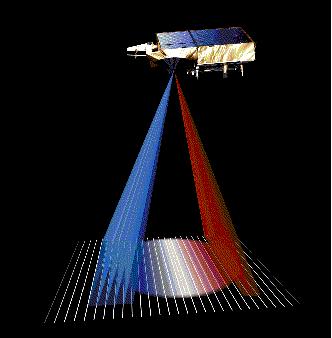
In the SAR mode, the resolution of the radar is improved in the along-track direction. This is achieved by exploiting the Doppler properties of the echoes as they cross the antenna beamwidth. The result is equivalent to decomposing the main antenna beam into a set of 64 narrower synthetic beams in the along-track direction. The footprints of the different sub-beams over a flat surface are adjacent rectangular areas, about 250 m wide in along-track and as large as the antenna's cross-track footprint (up to 15 km). Hence, a larger number of independent measurements are available over a given area; this property is used to enhance the accuracy of the measurements over sea ice. The echoes are transmitted to the ground segment in the time domain, prior to any averaging. Hence, the data rate in SAR mode is significantly higher than that for LRM.
· SARIn (SAR Interferometric) support mode. The objective is to provide improved elevation estimates over variable topography. This mode is used mainly over ice sheet margins with high surface slopes. Both receive channels are operating simultaneously at high PRF to ensure the availability of a high cross-track resolution used for ice sheet margins and coastal areas (accurate determination of the arrival direction of the echoes in along-track and in cross-track). This is needed to derive the height of the surface from the range measurement of the radar. Narrow-band tracking pulses, transmitted in-between successive wide-band measurement bursts are used in this range-tracking concept to cope with abrupt height variations.
In the SARIn mode, the addition of the interferometric feature to the SAR further improves the echo localization capabilities, as the cross-track direction angle of the echoes can be determined. This is achieved by comparing the phase of one receive channel with respect to the other.
The innovative technical features of SIRAL are:
· The capability to operate in all measurement modes
· Digital chirp generation with pulse to pulse coherence for Doppler processing
· Solid State Power Amplifier (SSPA) in Ku-band with high performance (25 W),
· Dual antennas forming an interferometer, mounted on an optical bench together with star- tracker heads, ensuring the accurate knowledge and stability of the interferometric baseline orientation
· Two receive chains matched together with very low distortions.
The novel feature of SIRAL, as compared with conventional altimeters, is the capability to locate a resolution cell in the 3 dimensional space. The SIRAL concept is based on a Ku-band nadir- looking radar which can be operated in the conventional mode over oceans. Over terrain (ice or land) the "advanced mode" uses Doppler filtering for the enhancement of the along-track resolution. A second antenna and receiving channel provides a second take of the scene which is used for surface height retrieval as it is usually done with SAR interferometry.
Parameter / Mode of Operation | LRM | SAR | SARIn |
Receive chain | 1 (left) | 1 (left) | 2 (left and right) |
Samples per echo | 128 | 128 | 512 |
Sample interval | 0.47 m | 0.47 m | 0.47 m |
Range window | 60 m | 60 m | 240 m |
Bandwidth | 350 MHz | 350 MHz | 350 MHz |
PRF | 1970 Hz | 17.8 kHz | 17.8 kHz |
Tx pulse length | 49 µs | 49 µs | 49 µs |
Useful echo length | 44.8 µs | 44.8 µs | 44.8 µs |
Burst length | N/A | 3.6 ms | 3.6 ms |
Pulses/burst | N/A | 64 | 64 |
Burst repetition interval | N/A | 11.7 ms | 46.7 ms |
Azimuth looks (46.7 ms) | 91 | 240 | 60 |
Tracking pulse bandwidth | 350 MHz | 350 MHz | 40 MHz |
Samples per tracking echo | 128 | 128 | 128 |
Size of tracking window | 60 m | 60 m | 480 m |
Averaged tracking pulses (46.7 ms) | 92 | 32 | 24 |
Data rate | 51 kbit/s | 11.3 Mbit/s | 2 x 11.3 Mbit/s |
Power consumption | 95.5 W | 127.5 W | 127.5 W |
Instrument mass (non redundant) | 62 kg | ||
DORIS (Doppler Orbitography and Radiopositioning Integration by Satellite)
DORIS (Doppler Orbitography and Radiopositioning Integration by Satellite). DORIS measures the Doppler frequency shifts of both VHF and S-Band signals transmitted by ground beacons. Its measurement accuracy is better than 0.5 mm/s in radial velocity allowing an absolute determination of the orbit position with an accuracy of 2-6 cm. DORIS is an uplink radio frequency tracking system based on the Doppler principle. The CNES instrument provides accurate measurements for a precise orbit determination. Knowledge of the orbit is essential for exploitation of the altimeter data and the overall performance. The onboard receiver measures the Doppler shift of uplink beacons in two frequencies (2.03625 GHz for Doppler measurement and 401.25 MHz for the ionospheric correction) which are transmitted continuously by the ground stations. One measurement is used to determine the radial velocity between spacecraft and beacon, the other to eliminate errors due to ionospheric propagation delays. The 401.25 MHz frequency is also used for measurements of time-tagging and auxiliary data transmission. The DORIS instrument comprises:
· A fixed omni-directional dual-frequency antenna
· A receiver performing the Doppler measurements every ten seconds. The nominal mode of operation is an autonomously programmed mode in which the receiver tracks the beacon signals according to information provided by the navigation software (DIODE) based on an on- board table of beacon data.
· An USO (Ultra Stable Oscillator) delivering the reference frequency with a stability of 5 x 10-13 over a period of 10 to 100 s.
The mass of DORIS is 15 kg (including the antenna of 160 mm diameter). The instrument requires 20 W of power, the data rate is 4 kbit/s.
The following DORIS services are used for CryoSat operations:
- Real-time orbit determination for spacecraft attitude and orbit control (on-board)
- Provision of a precise time reference based on TAI (International Atomic Time); in addition a precise 10 MHz reference signal is used (on-board)
- Provision of on-ground POD (Precise Orbit Determination) and ionospheric modelling.
The entire DORIS system comprises a network of more than 50 ground beacons, a number of receivers on several satellites in orbit and in development, and ground segment facilities. It is part of IDS (International DORIS Service), which also offers the possibility of precise localization of user-beacons.
LRR (Laser Retroreflector)
LRR (Laser Retroreflector), a passive optical device. The objective is to use LRR as an additional tool and backup for precise orbit determination with the aid of the international laser tracking network. LRR is accommodated in the nadir plate of the spacecraft, its FOV of ±57.6º is suitable for range measurements above 20º elevation angles at all azimuths from the ground. For any aspect angle the predicted rms target error is below 6 mm.
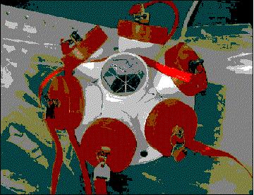
Prism material | Fused quartz |
Wavelength range | 310-1450 nm |
Reflective pattern width | 5-6 arcsec |
RMS target error | < 6 mm |
References
1) D. J. Wingham, "CryoSat: A mission to determine fluctuations in the Earth's ice fields," Proceedings of IGARSS 2002, Toronto, Canada, June 24-28, 2002
2) D. J. Wingham, "The first of ESA's Opportunity Missions: CryoSat," ESA Earth Observer Quarterly, No 63, Sept. 1999, pp. 21-24
3) http://www.esa.int/export/esaLP/cryosat.html
4) C. R. Francis, "Design of the CryoSat system,"Proceedings of IGARSS 2002, Toronto, Canada, June 24-28, 2002
5) M. R. Drinkwater, R. Francis G. Ratier, D. J. Wingham, "The European Space Agency's Earth Explorer Mission CryoSat: Measuring Variability in the Cryosphere," Seventh International Symposium on Antarctic Glaciology (ISAG7), Milan, Italy, August 2003
6) CryoSat Brochure of ESA, BR-199, 2003, ISSN No: 0250-1589, ISBN No: 92-9092-786-0 prepared by R. Francis and H. Rebhan
7) D. Wingham, "CryoSat: A Mission to the Ice Fields of Earth," ESA Bulletin No 122, May 2005, pp. 11-17
8) G. Ratier, R. Francis, C. Mavrocordatos, R. Zobl, "The CryoSat System - The satellite and its radar altimeter," ESA Bulletin No 122, May 2005, pp. 19-26
9) F. Rostan, U. Mallow, S. Riegger, "CryoSat Prelaunch Status and Performance," Proceedings of IGARSS 2005, Seoul, Korea, July 25-29, 2005
10) T. Usbeck, N. Duske, S. Schulz, "The CryoSat AOCS - A cost-efficient design for small Earth Observation satellites," 5th International ESA Conference on Guidance Navigation and Control Systems, Frascati, Italy, Oct. 22-25, 2002, ESA SP516
11) P. Smith, S. Edwards, N. Solway, "Cryosat Cold Gas System and Component Development," 40th AIAA/ASME/SAE/ASEE. Joint Propulsion Conference. July 11-14, 2004, Fort Lauderdale, FLA, USA
12) http://www.esa.int/esaCP/SEMQ13638FE_index_0.html
13) L. Rey, P. de Château-Thierry, L. Phalippou, C. Mavrocordatos, "SIRAL The Radar Altimeter for the CryoSat Mission - Pre-launch Performances," Proceedings of IGARSS 2003, Toulouse, France, July 21-25, 2003
14) L. Rey, P. de Château-Thierry, L. Phalippou, C. Mavrocordatos, R. Francis, "SIRAL: The Radar Altimeter for CryoSat mission under Development," Proceedings of IGARSS 2002, Toronto, Canada, June 24-28, 2002
15) L. Rey, P. de Château-Thierry, L. Phalippou, C. Mavrocordatos, R. Francis, "SIRAL, a High Spatial Resolution Radar Altimeter for the CryoSat Mission," Proceedings of IGARSS 2001, Sydney, Australia, July 9-13, 2001
16) L. Phalippou, L. Rey, P. de Chateau-Thierry, "Overview of the Performances and Tracking Design of the SIRAL Altimeter for the CryoSat Mission," Proceedings of IGARSS 2001, Sydney, Australia, July 9-13, 2001
This description was provided by Herbert J. Kramer from his documentation of: "Observation of the Earth and Its Environment: Survey of Missions and Sensors" - comments and corrections to this article are welcomed by the author (eoportal@symbios.space).