Wavemill 2D Ocean Current Mapping System
Airborne Sensors
Wavemill 2D Ocean Current Mapping System
The Wavemill 2D Ocean Current Mapping System is a microwave interferometric SAR concept proposed by Christopher Buck of ESA (2004, Ref. 8) to provide wide swath, high-resolution, high precision 2D maps of ocean surface topography and ocean vector currents.
Some Background of the Wavemill Concept 1) 2) 3)
Conventional altimeters provide extremely accurate measurements of the height of the ocean at the subsatellite point. A time series of these measurements is used in models to determine the larger scale ocean circulation, however, smaller scale features such as ocean eddies, are poorly sampled by conventional altimeters and their relatively fast movement means that it is very difficult to track them using these measurements. In addition, in general the data provided by conventional altimeters is unreliable close to coasts due to land contamination of the received signal.A means of mapping and monitoring such mesoscale ocean features was proposed by Ernesto Rodríguez (Ref. 2) in the form of the former WSOA (Wide Swath Ocean Altimeter) mission, now SWOT (Surface Water and Ocean Topography) mission. This concept makes use of cross-track interferometry over swaths on either side of the subsatellite track to determine the ocean height over these swaths.
The 'Wavemill' concept proposed by Christopher Buck (Ref. 3) shares some of the same principles of WSOA but by means of multiple squinted beams fore and aft of the satellite, it is able to combine both across-track interferometry, as in the WSOA case for the determination of sea-surface topography, with along-track interferometry, for direct measurement of the ocean surface current. Moreover, since the antenna beams are squinted both fore and aft, the surface current is imaged from different (nearly orthogonal) directions from which true two dimensional ocean surface currents may be determined.
The Wavemill instrument concept is a hybrid interferometric system, which combines both XTI (Cross-Track Interferometry) for the determination of sea-surface topography, and ATI (Along-Track Interferometry) for the measurement of the total ocean surface current velocity. By means of multiple squinted beams fore and aft of the satellite, the surface can be imaged from different nearly orthogonal directions, from which true two dimensional maps of ocean surface topography and total ocean velocity may be determined over a broad swath. 4) 5)
The Wavemill concept attempts to retain the WSOA benefits while solving its calibration limitations and additionally, to measure directly 2D surface ocean currents. These outstanding features can be obtained by separating the two antennas not only in the cross-track direction but also in the along-track direction. This configuration allows direct measurement of 2D ocean surface currents by ATI while keeping the ability of WSOA to measure ocean geostrophic currents by XTI. The possibility of current measurements by combined ATI/XTI, also known as hybrid interferometry, has been successfully demonstrated in the past from airborne platform with repeated passes. 6)
However, the proposed space instrument aims to 2D current measurements with a solely satellite single pass. The main features of Wavemill are (Ref. 5):
• Interferometric side-looking SAR (Synthetic Aperture Radar) operation.
• Right- and left-hand side-looking observation to acquire a total combined swath of 200 km. This configuration also allows for 2D ocean current observations and at the same time is required for the baseline calibration.
• Two beams squinted 25º fore (along-track direction) and aft (counter along-track direction) to measure 2D ocean surface currents. Although a 45º squinted geometry is optimum in terms of current estimation, it also requires a larger LOS swath, i.e. 141 km compared with the 111 km for the 25º case. The accommodation of a larger swath is problematic for the timing analysis and has been avoided.
• Incidence angle of 16º at mid swath to best trade sea surface height and currents off. Although 30º-45º is more appropriate for sea surface current estimation, a steeper incidence angle is better for sea surface height estimation, timing and signal-to-noise ratio (SNR), i.e. interferogram coherence.
• Two channels per observation: monostatic and bistatic. One antenna transmits and receives; a second one only receives.
• Four beams pulsed sequentially in a burst operation mode. This reduces the number of receivers from 8 to only 2 which are switched to each active beam. Additionally, the required power (launcher selection) and the processed data amount will be significantly reduced.
The Four Antenna Concept
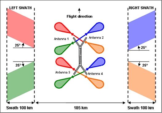
The original Wavemill concept was proposed by ESA (Ref. 8) and was then the subject of a Feasibility Study. Two swaths of 100 km width on each side of the subsatellite track were illuminated (Ref. 9). Along and across track interferometry (ATI and XTI) are combined in the same instrument so that ocean surface current velocity and direction can be determined by ATI and ocean surface topology by XTI. 7) 8) 9) 10)
The first instrument design proposed was based on a four antennas supported on opposite ends of a platform boom structure. Each antenna structure was inclined at 25 to 45º to the flight direction to provide the beam squint. The beams were broadside to the antenna face. The 'rooftop design' of the antenna structures was based on well established, end fed slotted waveguide technology as shown in Figure 2(a).
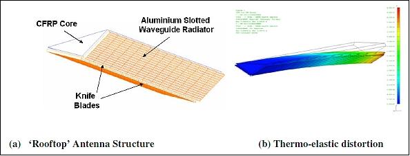
The predicted performance of this design was very encouraging (Ref. 10). However the rooftop design resulted in differential heating across the antenna and consequent thermo-elastic distortion as shown in Figure 3 (b). It was possible to mitigate the effects of this distortion by careful design and thus ensure satisfactory predicted performance (Ref. 9). An alternative antenna design was proposed which does not suffer from the problem of differential heating and this 'Javelin' concept will be considered in addition to the original four antenna concept.
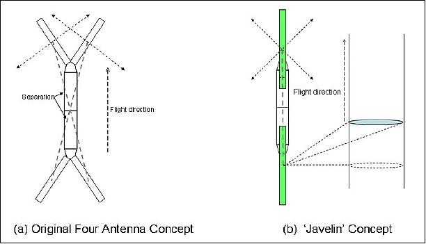
The Javelin Concept
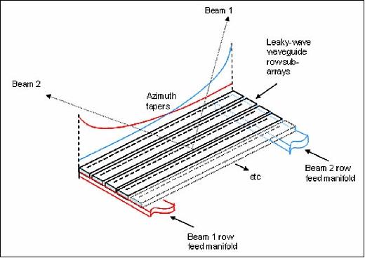
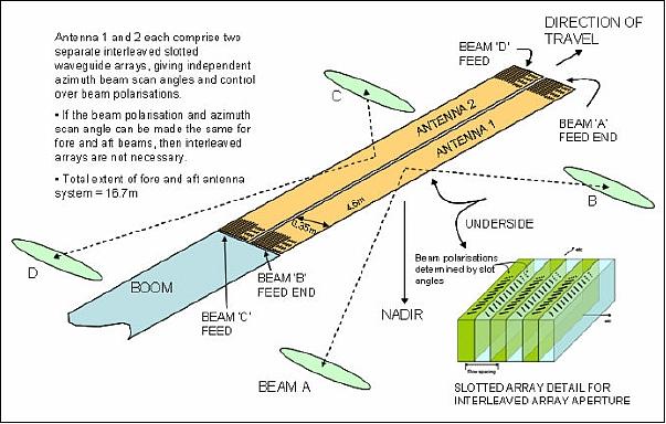
This concept features just two 'in–line' antenna structures. The beam footprints will look fore and aft but be oriented broadside to the subsatellite track (Figure 3). The Javelin concept is potentially a simpler structure which should have a number of significant advantages in terms of complexity and cost compared with the four antenna concept. The two 'in-line' antenna structures would be nadir pointing which has the immediate advantage that the radiating face for the various beams experiences the same solar flux. The orbit can be chosen so that the sun never shines on the front face of the antenna. Each beam would have a fixed scan relative to the antenna face. It is also a simpler structure which will have immediate advantages for stowage and deployment. The nadir pointing antenna structure achieves fore and aft squinted beams by scanning the beam in azimuth through the use of a leaky wave concept. As a result the illuminated beam footprints are always broadside to the subsatellite track. This is fundamentally different from the baseline concept where the footprints are aligned with the beam direction. The two Wavemill concepts are shown in Figure 3.
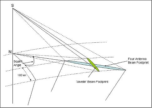
The leaky wave antennas will have a fixed scan angle relative to the antenna face but the squint angle of the illuminated footprint on the ground varies with distance as can be seen in Figure 4. Although the antenna structures are in-line along the direction of motion, the cross track baseline arises because of the beam squint, there is no across track baseline in the broadside direction.
The antenna design is shown in Figure 5. The antenna radiates through closely spaced non-resonant slots having low individual coupling to the propagating waveguide mode and the squinted beam is dependent only on ratio of free space and guide wavelength. It can be fed independently from either end generating plus and minus scan angles as required by Wavemill. A minimum scan angle of around 15º is required to avoid cut-off. Two side by side antenna structures with interleaved arrays are deployed at each end of the boom as shown in Figure 6.
The challenge for the thermo / mechanical design is to ensure that the beams are co-located with sufficient accuracy. It was also important to avoid high risk solutions. The antenna design consists of aluminum waveguides connected via aluminum alloy blade mounts to a tapered CFRP box section. They are mounted on box section booms which are used to provide the necessary phase centre separation. On one side the antenna is held rigidly closest to the spacecraft and on the other it is held at the end furthest from the spacecraft to ensure that the thermo-elastic distortions are in the same direction. The critical relative pointing change between a pair of beams due to thermo elastic effects round the orbit is similar for both aluminum and CFRP. The higher thermal mass of aluminum and the fact that the aluminum antennas are mounted on metallic knife blades mean that these thermo elastic distortions occur much more slowly around the orbit for the aluminum waveguides. Aluminum waveguides are recommended. An additional factor is that the internal surface of the aluminum waveguide can, at present be manufactured to a higher tolerance which affects the pointing accuracy of the leaky wave antenna.
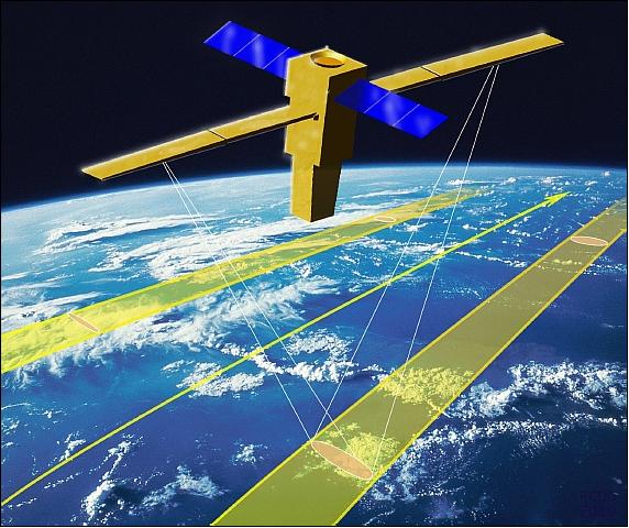
A 'Snapdragon'-class deploying platform was assumed for the earlier four antenna concept but a classical modular spacecraft was assumed for Javelin. The Wavemill system can therefore deployed on either class of platform as shown in Figure 7. The estimated Wavemill instrument mass is 330 kg and the total instrument power is 4110 W.
Wavemill Project Preparation Steps
Wavemill attempts to retain many of the benefits of WSOA/SWOT concept, which is aimed at extending the resolution coverage of conventional ocean surface topography measurements. The Wavemill concept proposes simultaneous imaging of swaths to either side of the sub-satellite track allowing SAR interferometry of the ocean surface. The Wavemill antenna configuration basically consists of separating two antennas in both the across-track and along-track directions (i.e. parallel to the flight track), allowing the 2D ocean surface currents to be measured directly by means of ATI (Along-Track Interferometry) while maintaining the ability of WSOA to measure ocean topography over swaths by means of XTI (Cross-Track Interferometry). The baselines required for the Ku-band (13.3 GHz) system under study are around 3.5 m cross-track and 12.5 m along-track. Despite these relatively modest dimensions, the system performance is predicted to be very good. 11)
Under ESA contract, Starlab (Barcelona, Spain) and Astrium Ltd. (Portsmouth, UK) have conducted a feasibility study on Wavemill and the conclusions are promising both in terms of performance and instrument design. The results suggest that currents of less than 10 cm/s are measurable and the directional accuracy, although dependent on the strength of the current, is of the order of 10º for currents of 40 cm/s dropping to a few degrees for fast currents of around 1 m/s. Due to the geometry and antenna patterns, ambiguous energy from land will not be a serious issue making Wavemill very useful for the monitoring of coastal currents.
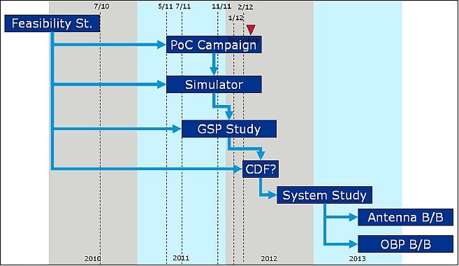
Following the positive outcome of the feasibility study (Ref. 7), the Agency has started to initiate a number of steps towards the establishment of a full science, instrument and mission concept for the retrieval of ocean currents. These steps are set out as follows (Figure 8):
- A PoC (Proof-of-Concept) campaign with squinted interferometric SAR capability
- Development of an end-to-end simulator towards the end of which there will be a workshop to present the findings to the scientific community
- A GSP (General Scientific Product) assessment study
- Potentially an internal CDF (Concurrent Design Facility) study to help focus the system study
- A system study
- Risk retirement in the form of: a) antenna breadboard, and b) on-board processor breadboard.
PoC (Proof-of-Concept) Campaign
The main precepts of the Wavemill instrument (i.e. squinted hybrid interferometry) and the specific processing required have yet to be proven conclusively, but if this is achieved, then Wavemill represents an extremely innovative and significant instrument regarding the study of the oceans. Proving the Wavemill measurement concept is the purpose of the Wavemill PoC campaign. The current plan is to fly Astrium's X-SAR instrument in the Wavemill configuration over a test site with "ground truth" provided by HF radar, buoys and acoustic Doppler current profilers. Ideally this will take place under a variety of wind and tide conditions.
The findings of the WPCC campaign will be an important step in understanding the true potential of Wavemill for oceanography and this is to be achieved by flying an interferometric SAR instrument with squinted beams in order to demonstrate the feasibility of the Wavemill concept and to obtain a better understanding of the products that could be derived form a Wavemill instrument (Ref. 11).
Wavemill Scientific Objectives | Primary or Secondary objective | ESA's Living Planet Program challenges addressed |
1. Quantify and map (sub)-mesoscale (<0.1 – 10 km) ocean surface current vectors and their variability | P | Ocean: |
2. Quantify and map (sub)-mesoscale sea surface height and its variability | P | Ocean: |
3. Evaluate and reduce the uncertainty of (sub)-mesoscale ocean surface current variability measurements at regional and global scales | P | Ocean: |
4. Quantify and map ocean swell and waves at regional and global scales | P | Ocean |
4. Quantify and map the variability of sea ice, sea ice thickness and velocity | P | Cryosphere: |
5. Quantify and map the size, velocity and the variability of icebergs | S | Cryosphere: |
6. Quantify and map river flows and river flow variability | S | Land: Challenges 1 and 3 |
7. Improve and validate numerical ocean circulation model and data-based assessment and prediction of ocean circulation | P | Ocean: |
8. Improve and validate hydrological models through data assimilation and improve freshwater inflow into the ocean. | P | Land: |
Antenna Breadboard
This activity covers the development of a prototype Wavemill antenna. The feasibility study, demonstrated the value of the "javelin" concept since it can provide the required along- and across-track baselines despite a compact spacecraft at launch and one which is nearly optimal for AOCS (long and thin in the flight direction). However, this design calls for an antenna capable of producing up to four squinted beams with a swath width of around 100 km at an incidence angle of 25-45º. This key component needs to be addressed and realized in a breadboard to bring the whole Wavemill concept together.
From the feasibility study (Figure 5) it seems that a specific type of slotted waveguide antenna known as a 'leaky wave' antenna should be able to produce the required beams since it has the property of naturally squinting to 45º with swaths on the ground orthogonal to the subsatellite track. This will save power and data rate. A breadboard of such an antenna operating in Ku-band with > 100 MHz bandwidth shall be designed, manufactured and tested in this activity.
On-Board Processor Breadboard
This activity covers the development of a prototype on-board processor for Wavemill. With its four interferometric pairs of SAR images, Wavemill produces an enormous amount of data at a very high data rate. Fortunately, due to the fact that the signal (phase) quality is required, rather than spatial resolution, a very high amount of multi-looking can be performed on the images on board, drastically reducing the quantity of data to be downlinked.
The activity is to cover the full on-board processing steps for Wavemill, which include:
- SAR processing
- Image registration
- Co-time interferogram generation
- Multi looks
- Flat Earth correction
- Hybrid interferogram generation
- Hybrid phase separation.
The design shall be based on FFT (Fast Fourier Transform) and processing chipsets (e.g. PowerFFT and Leon II) which are functionally representative of space-qualified components (Ref. 11). 12)
Wavemill PoC (Proof-of-Concept) Airborne Campaign Overview
The POC campaign is based on modifying the existing Astrium airborne SAR instrument to provide the functionality required, and then flying the modified instrument over selected ocean scenes to acquire data. It will then also include processing of that data to produce current measurements and hence prove the concept of operation of Wavemill by comparison with independently and simultaneously acquired 'ground truth' from the scene. 13)
Instrument Design
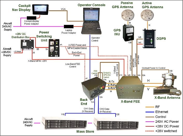
The existing instrument (Figure 9) includes a back-end electronics that generates the transmit waveforms, controls the timing of all radar activities, and digitizes the down-converted echo signals. It also controls the front-end electronics. The back-end records radar data to a separate mass storage system; there is a RAID (Redundant Array of Independent Disks) array comprising solid state hard drives. A RAID 10 configuration is used to protect against loss of a hard drive. The instrument is operated from a laptop computer which enables the operator to select a pre-planned run and configure the instrument to perform that run. The operator also has displays showing the desired and actual aircraft position in realtime, and this part of the operator display is repeated in the cockpit on a small monitor to enable the pilot to fly accurate tracks. A dedicated GPS-INU unit with space-based DGPS augmentation is used to provide the motion data that is used for navigation in real-time, and stored for later use in the image processing off-line after each flight.
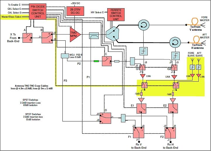
The front-end electronics comprises the 100 W HPA (High Power Amplifier) for transmit, a high power switch for transmit polarization switching, and receiver paths incorporating limiters and LNAs (Low Noise Amplifiers). The front-end also includes a number of calibration paths to enable accurate characterization of the system distortions. For the Wavemill PoC campaign, the existing dual-polar antenna will be replaced by four single-polar horn antennas, two pointed fore and two pointed aft of the broadside look direction such that a 'squint' of 90º (about nadir) exists between the two look directions.
Each pair of antennas comprises a Master and a Slave. Each Master is used for transmit and receive, whereas each slave is only used for receive. The original H and V antenna ports are re-designated as Fore Master and Aft Master ports. The two slave antennas need to be routed into the existing two receive paths, and this is to be accomplished using SPDT (Single-Pole Double-Throw) PIN diode switches. In order for the insertion loss of these switches to have minimal impact on image signal to noise ratio, they are to be positioned after the LNAs. Therefore two additional LNAs are needed for the slave antennas, with associated limiters protecting their inputs. Sufficient stability and tracking is expected between these LNAs and the existing LNAs in the master receive paths that their inclusion in the calibration paths is not considered necessary, although this could be implemented at a later date in the unlikely event that it proves necessary in practise. The block diagram below shows the front-end architecture, with the new items highlighted in yellow, including the new control signal that is needed to control the Master / Slave receive select switches.
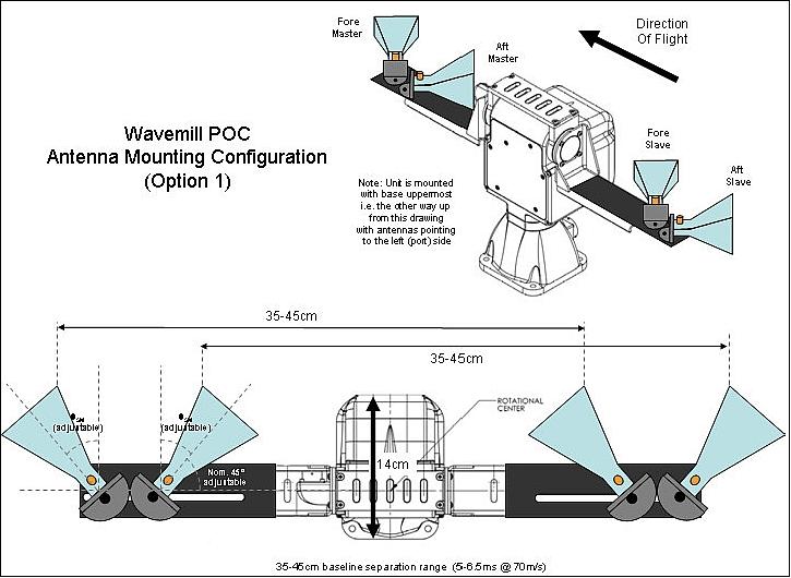
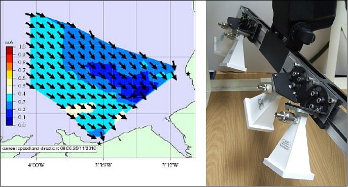
The antenna configuration required involves the mounting of four identical horn antennas on a single beam that nominally flies parallel to the planned aircraft track. To maintain the stability of the pointing of this beam a pan/tilt gimbal unit is used, with a real-time control solution based on inputs from the GPS-INU (GPS-Inertial Navigation Unit). The diagram (Figure 11) shows the preferred mounting configuration. This enables Master/Slave baseline separations in the range 34–62 cm to be implemented. Shorter baselines (10-24 cm) are possible using the same structure by mounting fore antennas together on one end of the boom, and aft antennas together on the other end.
Mode design: A suitable mode needs to be designed to achieve adequate signal to noise ratio over a suitable swath width at a suitable incidence angle. Care must be taken that the timing of transmit and receive is appropriate for the squinted antenna beam look direction geometry. Also, the effective pulse repetition frequency must be sufficiently high to adequately sample the illuminated Doppler bandwidth. Astrium has existing tools for mode design that will be used to assist in this process.
Intermediate Radar Data Generation
The radar data this is acquired needs to undergo a significant number of processing steps to achieve the objectives of the campaign. The first steps involve motion compensation (using recorded motion data from the GPS-INU) and range processing of the data. These steps are already implemented in the existing Astrium airborne SAR processor that accompanies the existing instrument. However the subsequent remaining steps, including azimuth processing and interferometric processing, are specific to the Wavemill PoC campaign. For this reason, it has been decided that Astrium will perform the first stage of processing and then output the data to an 'Intermediate Data File' that contains all the information and data necessary for the subsequent second stage of processing, which will be performed by Starlab.
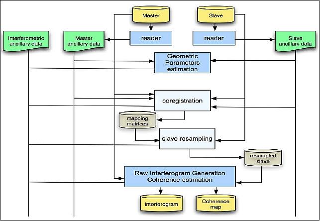
Interferometric data processing: Figure 12 is a block diagram of the interferometric processor for the Wavemill-PoC campaign. Blocks in blue represent processing steps, yellow cylinders image data and green blocks metadata. The processor will first read the intermediate data files from the Stage 1 processing and perform azimuth processing. It will then perform co-registration and raw interferogram generation, resulting in an interferogram and a coherence map. Significant multi-looking will be involved in order to achieve the accuracies required for ocean current measurement.
Planning of Trials
The National Oceanographic Center (UK) will support the campaign preparation, site selection and scientific interpretation of the retrieved geophysical data. A key site identified for the trials campaign is in the Liverpool Bay area off the North coast of Wales (Figure 13), where an HF radar and other oceanographic instruments are in operation to provide ground truth. Other sites will also be considered.
Campaign Program Status
Work is progressing well toward the goal of a first flight trial in Q4 2011. The back-end is essentially unchanged, but the front-end has additional hardware. The new control signal has been implemented, and a Wavemill 'shelf' has been added to accommodate the limiters, LNAs and SPDT RF switches.
References
1) Christopher Buck, Marco Caparrini, José Marquez, Byron Richards, David Lancashire,: "The Wavemill Concept for Direct Measurement of 2D Ocean Surface Currents," OceanObs'09 "Ocean information for society: sustaining the benefits, realizing the potential".Venice, Italy, Sept.21-25, 2009, URL: http://www.oceanobs09.net/proceedings/ac/FCXNL-09A02-1675797-1-1675797.doc
2) Ernesto Rodriguez, Brian D. Pollard, Jan M. Martin, "Wide-Swath Ocean Altimetry Using Radar Interferometry," IEEE Transactions on Geoscience and Remote Sensing, July, 1999, URL: http://trs-new.jpl.nasa.gov/dspace/bitstream/2014/17962/1/99-1415.pdf
3) Christopher. Buck, "An Extension to the Wide Swath Ocean Altimeter Concept," Proceedings of the IEEE IGRARSS (International Geoscience and Remote Sensing Symposium), Seoul, Korea, July 25-29, 2005, pp 5436-5439
4) Christine Gommenginger, Alex Wishart, Meric Srokosz, Byron Richards, "The Wavemill 2D Ocean Current Mapping System: On-Board Signal Processing and Architecture Definition," URL: http://www.aviso.oceanobs.com/fileadmin/documents/OSTST/2010-Gommenginger_Wavemill.pdf
5) José Márquez, Giulio Ruffini, Dave Lancashire, Byron Richards, Christopher Buck, "Wavemill: A Novel Instrument for Ocean Circulation Monitoring," Proceedings of EUSAR 2010, 8th European Conference on Synthetic Aperture Radar, June 7-10, 2010, Aachen, Germany
6) Robert Siegmund, Mingquan Bao, Susanne Lehner, Roberto Mayerle, "First Demonstration of Surface Currents Imaged by Hybrid Along- and Cross-Track Interferometric SAR," IEEE Transactions on Geoscience and Remote Sensing, Vol. 42, No 3, pp. 511-519, March, 2004, URL: http://www.geo.uzh.ch/microsite/rsl-documents/research/SARlab/GMTILiterature/PDF/SBLM04.pdf
7) B. E. Richards, D. C. Lancashire, J. Marquez, C. Buck, "Wavemill Oceanographic Radar - Design and Performance Update," Proceedings of the 3rd Workshop on Advanced RF Sensors and Remote Sensing Instruments (ARSI), Noordwijk, The Netherlands, Sept. 13-15, 2011, URL: http://www.congrex.nl/11c11/ARSI%20papers/Richards%20et%20al_Wavemill_ARSI%202011PDF.pdf
8) Christopher Buck, "Wavemill Concept", ESA Technical Note, TEC-ETP/2004.121/CBu
9) B. E. Richards, D. C. Lancashire, J. Márquez, C Buck, " Wavemill Ocean Current Radar : Instrument Design", Advanced RF Sensors and Remote Sensing Instruments, ESA/ESTEC, Noordwijk, The Netherlands, November 16-18,, 2009
10) J. Marquez, G. Ruffini, D. Lancashire, J. Isern-Fontanet, C Buck, "Wavemill: A needed instrument for ocean circulation monitoring", Advanced RF Sensors and Remote Sensing Instruments, ESA/ESTEC, Noordwijk, The Netherlands, November 16-18,, 2009
11) C. Buck, C. Donlon, D. Petrolati, S. D'Addio, "A Roadmap for Wavemill," Proceedings of the 3rd Workshop on Advanced RF Sensors and Remote Sensing Instruments (ARSI), Noordwijk, The Netherlands, Sept. 13-15, 2011, URL: http://www.congrex.nl/11c11/ARSI%20papers/BUCK_A%20Roadmap-20for%20Wavemill.pdf
12) Daniele Petrolati, Salvatore D'Addio, Christopher Buck, "Critical assessment of system performance and error impacts on bi-dimensional ocean surface current measurements for Wavemill concept," Proceedings of IGARSS (International Geoscience and Remote Sensing Symposium), Vancouver, Canada, July 24-29, 2011
13) Martin Cohen, José Marquez, Christopher Buck, "Wavemill Proof-of-Concept Campaign – Programme Summary and Status," Proceedings of the 3rd Workshop on Advanced RF Sensors and Remote Sensing Instruments (ARSI), Noordwijk, The Netherlands, Sept. 13-15, 2011, URL: http://www.congrex.nl/11c11/ARSI%20papers/COHEN-Wavemill%20Proof-of-Concept%20Campaign%20-%20
Programme%20Summary%20and%20Status%20-%20ARSI%202011.pdf
The information compiled and edited in this article was provided by Herbert J. Kramer from his documentation of: "Observation of the Earth and Its Environment: Survey of Missions and Sensors" (Springer Verlag) as well as many other sources after the publication of the 4th edition in 2002. - Comments and corrections to this article are always welcome for further updates (eoportal@symbios.space).