UWE-4 (University Würzburg Experimental satellite-4)
Non-EO
Quick facts
Overview
| Mission type | Non-EO |
| Launch date | 27 Dec 2018 |
UWE-4 (University Würzburg Experimental satellite-4)
Spacecraft Launch Mission Status Experiment References
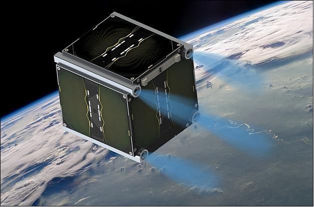
The UWE-4 is the most recent project of the University of Würzburg, Germany, within the roadmap towards formation flying CubeSats and will incorporate for the first time in the UWE program a propulsion system.The project started in 2015 and is scheduled for launch in early 2018. 1) 2)
The technical objective of the UWE-4 mission is the in-orbit demonstration and characterization of an electric propulsion system for 1U CubeSats. For this, the project cooperates with the TU Dresden that develops the NanoFEEP propulsion system. 3) This system fits the CubeSat’s strict requirements in terms of size and power consumption, and has therefore been selected as the UWE-4 technical payload. The propulsion system consists of the thruster heads that are being integrated into the CubeSat rails and the PPU (Power Processing Unit) that is realized as standard subsystem according to the UNISEC (University Space Engineering Consortium) Europe standard . 4) The primary technical mission objective is to activate the thrusters and measure their thrust in different operating ranges. Secondary objectives include attitude control using the four thrusters and eventually basic orbit control maneuvers. 5)
Spacecraft
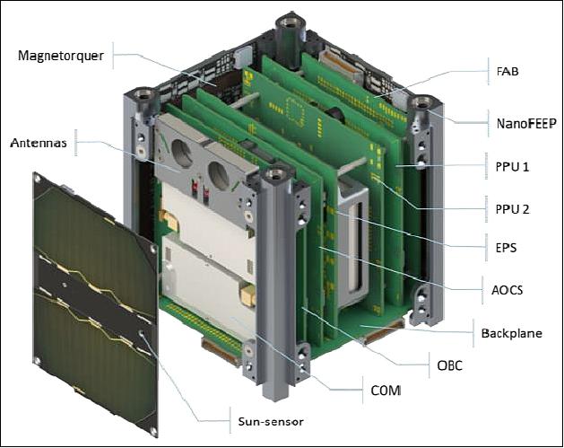
The UWE-4 satellite is based on the architecture introduced by UNISEC Europe which has been demonstrated first on UWE-3. It makes use of a backplane which interconnects all subsystems with a standardized interface and also interfaces the CubeSat’s panels. This architecture supports rapid development, test, and integration of new subsystems. It provides several redundant communication busses (I2C, UART, and MLVDS) and power busses, dedicated synchronization signals, and complete debug access to each subsystem. The subsystem stack as shown in Figure 2 consists of the OBC, AOCS (Attitude and Orbit Control System), the PPU, the EPS ( Electrical Power Subsystem), COM (UHF Communication System), and the FAB (Front Access Board). ). Beyond Europe, it is also applied in the Japanese BIRDS-1 and -2 satellites and has been used in industry by Airbus DS.
Key satellite aspects to formation flying and technology transfer to products are handled by ZfT (Zentrum für Telematik e.V.), Würzburg, while the University Würzburg focusses on basic research. Thus UWE-4 benefits from the ZfT developments related to the OBC (On-Board Computer), as well as the attitude determination sensor suite and control system.
The UWE-4 OBC profits from its heritage of the precursor satellite UWE-3 and was further developed in cooperation with ZfT (shown in Figure 3).
The ZfT onboard computer features two redundant low-power commercial microprocessors fully interconnected in order to repair and restore one another in case of radiation induced failures. Both processors are monitored by a watchdog cascade in order to detect faulty behavior. One of the precursors, the UWE-3 OBC, has proven its reliability by seamless operation since launch in 2013. Its purpose is to monitor the overall health status of the satellite and to allow communication from ground with all subsystems through the redundant COM system. Its power consumption of <15 mW guarantees that it is always switched on, even in severe low-power conditions. Furthermore, the OBC carries its own latchup-protection with automatic power cycling capability and a backup power conditioning unit.
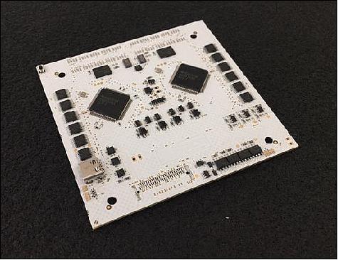
The new developments focused on an enhanced implementation of the redundancy concept for increased robustness and on extending the system’s debug access to other subsystems. Therefore, the system now carries two independent high precision real-time clocks, employs several independent FRAM chips with a total storage capacity of 40Mbit, a set of 4Gbit NAND Flash memory chips, and a pair of microSD card slots. Furthermore, it implements debug interfaces to all other subsystems’ microprocessors which includes 4-Wire-JTAG and Spy-Bi-Wire (2-Wire-JTAG) for other TI MSP microcontrollers, and SWD (Serial Wire Debug) for support of ATMEL ARM processors. This debug access further extends the system’s capability for fail-safe in-orbit software updates, extending significantly the already successfully demonstrated capabilities of UWE-3.
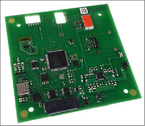
The UWE-4 AOCS (Attitude and Orbit Control Subsystem) inherits its basic setup from the earlierUWE ADCS. It is implemented as standard subsystem carrying a low-power microcontroller that fuses sensor data from magnetometers, sun-sensors, and gyroscopes, and computes attitude and orbit control outputs for the satellite’s magnetorquer and propulsion system. The system is shown in Figure 4.
The sensor suite is enhanced, but the original sensors have been kept as backup. The microcontroller now has access to a primary highly integrated MEMS 9-axis IMU (each 3-axis magnetometer, gyroscope, and accelerometer) placed on the AOCS board itself as well as a set of secondary magnetometers and high precision gyroscopes. Each CubeSat panel carries a redundant IMU and a high precision sun-sensor. All sensors’ data can be injected into the Kalman filter sequentially and independently, such that a coarse attitude determination is also available during eclipse.
The sun-sensors are based on an ultra-low power miniature CMOS camera with a field of view of more than 90º at 250 x 250 pixel resolution and nominal power consumption of only 4.2 mW. Preliminary calibration results indicate that a sensor accuracy of better than 0.1º is achievable and an accuracy of down to 0.01º might be achievable in the future. Shown in Figure 5 are the miniature sun-sensors in front of an UWE-3 panel with its digital coarse sun-sensor in the background.
Attitude control is performed with the help of magnetic torquers and the propulsion system. The torquers are placed on each panel with a total magnetic moment of 0.1Am2 per axis and are mainly used for angular rate control. The four thrusters are used for precise thrust axis pointing. Although the thrusters can only exert a weak torque of up to 1µNm each, the limited magnetic controllability of the satellite is completed and simulations show that a thrust vector pointing is feasible. The hybrid attitude control algorithms are tested in a simulation in-orbit data from UWE-3.
Special care has been taken in order to minimize the satellite’s magnetic dipole which has been a major disturbance of the UWE-3 attitude control efforts. As such, the CubeSat’s antenna material has been exchanged and the main structural components are manufactured from aluminum or titan.
The attitude determination system also plays an important role in the accomplishment of the technical mission objective. Since the electric propulsion system produces very small thrust levels in the µN range its precise characterization is difficult to achieve via an orbit determination process. However, even very small torques on the satellite are measurable by the attitude determination system as demonstrated during the UWE-3 mission. There, the residual magnetic dipole moment was estimated by analysis of the passively acting magnetic disturbance on the satellite’s dynamics. The measured torque levels also are between 0.1 µNm and 5 µNm and vary according to the satellite’s motion with respect to the Earth’s magnetic field. The thrusters, however, generate a torque that is time invariant in body coordinates and consequently even better to distinguish from noise and also other perturbations. Therefore, the same algorithm used in UWE-3 for estimation of the residual magnetic dipole will be used in UWE-4 for precise thrust estimation of each thruster.
After having accomplished the primary technical objective of thrust estimation and determination of the operation characteristics of the propulsion system, the goal is to perform basic orbit control maneuvers. For this, the satellite will point its Z-axis (thrust vector axis) in in-track direction and thrust in vicinity of the orbit’s apogee. This will slowly lower the orbit and will be visible in orbit estimation data from NORAD thereafter. Simulations show, that by this technique a perigee lowering of about one kilometer per week is feasible. In future applications, such as the formation flying mission NetSat, the propulsion system will give 1U CubeSats a total maneuvering capability of up to ΔV = 60 m/s. For comparison, the complete CanX-4/-5 mission required for various formation flying experiments approximately 5m/s of ΔV.
EPS (Electric Power Subsystem): The EPS of UWE-4 continues the distributed architecture from earlier UWEs. The solar cells’ power is directly tracked on each panel and supplied to the batteries. The EPS board itself carries two redundant 2.6 Ah Li-ion batteries and several power conditioning units for the regulated 3.3 V and 5.0 V power busses. Power distribution is realized through the standardized subsystem interfaces which are controlled through the OBC. The batteries are monitored and protected against low voltage conditions and the power conditioning units passively distribute the actual power demand among them. The satellite’s power busses can be generated by one of the two power paths (battery & power conditioning units) or both in parallel for power demanding applications. The standardized subsystem interfaces provide power monitoring, latchup-, over-voltage and under-voltage protection for each subsystem individually.
New EPS features include analog MPPT (Maximum Power Point Tracking) electronics are placed on each panel for improved voltage stability at each cell’s optimal operating point. Furthermore, the power switching of the satellite has been revised and the changes made will further enhance the overall satellite efficiency.
Launch
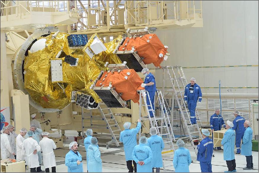
The UWE-4 nanosatellite was launched on 27 December 2018 (02:07 UTC) as a secondary payload on the Kanopus-V No 5 and No 6 minisatellite flight (each ~490 kg) of Roscosmos on a Soyuz-2.1a / Fregat-M vehicle from the Vostochny Cosmodrome. 6) 7) 8)
Secondary Payloads
• GRUS-1, a microsatellite (100 kg) of Axelspace, Japan. The spacecraft is the first in a fleet of Earth-imaging satellites planned by Axelspace to eventually return pictures of the entire planet every day. GRUS-1 imagery has a resolution of 2.5 m on a swath of 60 km.
• ZACUBE-2, a 3U CubeSat (4 kg) of CPUT (Cape Peninsula University of Technology), Cape Town, South Africa.
• Lume-1, a 2U CubeSat (2 kg) of the University of Vigo, Spain.
• Lemur-2 x 8, Eight 3U CubeSats (each ~4 kg) of Spire Global, San Francisco, CA
• D-Star One iSat, a 3U CubeSat (4 kg) of iSky Technology, Germany.
• D-Star One Sparrow, a 3U CubeSat (4 kg) of German Orbital Systems
• UWE-4, a 1U CubeSat of the University of Würzburg, Germany.
• Flock-3k x 12, Twelve 3U imaging CubeSats (each ~ 5 kg) of Planet Labs, San Francisco, CA.
Orbit: The Fregat upper stage aimed to drop off the twin Kanopus satellites into an orbit of 522 km in altitude and 97.4º inclination, before reigniting to release a dozen more small satellites into an orbit of 585 km, according to Roscosmos.
Mission Status
• August 2019: The technical mission objective is to demonstrate the electric propulsion system NanoFEEP, developed by our partners at TU Dresden on-board a 1U CubeSat, characterize it and use it for orbit control purposes. 9)
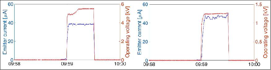
- The first activation of the electric propulsion system took place on 26 February 2019 at 09:59:00 UTC, after a heating process for at least eight prior orbits. The UWE-4 satellite could successfully ignite one of its NanoFEEP thrusters for a duration of 30s at an operating voltage of more than 5.4 kV and neutralize the emitted charge with an on-board neutralizer. The measurement of the emitted current and the operating voltage of the thruster and the neutralizer is depicted in Figure 7. It is necessary that the neutralizer current is never smaller than the thruster current in order to prevent a negative satellite potential from which the satellite could not recover solely by the interaction with the space plasma.
- Attitude Control Capabilities: The air coils, which are located on each side panel facilitate the creation of a maximum magnetic moment of 0.1 Am2per body axis. However, the characteristic of a pure magnetic controller to create only torques perpendicular to the external magnetic field limits the magnetic control capabilities. Additionally,the electric propulsion system can create torques around body x-and y-axis. Thus, it can augment the attitude control capabilities of a pure magnetic controller. Each thruster head contains 0.25 g Gallium as propellant and can create a thrust of up to 20 µN and thus a torque of up to 0.8 µNm.
- Initial thruster experiments as attitude control actuator. On 4May 2019, an initial experiment to the effect of the propulsion system on the satellite’s attitude was conducted. For this purpose the thruster located in the +X+Y+Z corner of the CubeSat has been activated with an emitter current of 80 µA and an operating voltage of 6.3 kV. At the same time the neutralizer was operated at more than 1.3 kV to emit an electron current to compensate the thruster current. The effect of the emitted thruster ions on the satellite’s rotation rate can be seen in Figure 8.
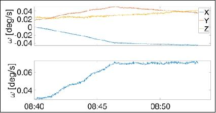
- As visible in Figure 8, the thruster was activated between 08:40:11 UTC and 08:46:16 UTC. During this time the rotation rate of the satellite increased from approx. 1.7 º/s to more than 4.0º/s. The electrical characteristics in this figure justify the assumption of a roughly constant emitter current and thus a constantly created thrust.
- In summary, a milestone in the 1U CubeSat development was reached with the activation of an electric propulsion system. The attitude determination sensors were calibrated, but the isotropic Kalman filter can still be improved with a proper tuning of its parameters. Initial attitude control experiments with the magnetorquers were conducted and the influence of the thrusters on the satellite’s attitude is currently being investigated. In the upcoming weeks, this will result in attitude control experiments with the magnetorquers as main actuators and the thrusters in order to augment the capabilities of the AOCS. Finally orbit control experiments, focusing on a change of the semi-major axis will be conducted.
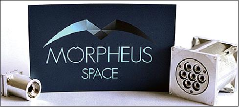
• February 27, 2019: After 7 years of tireless development at the TU Dresden, the spin-off, Morpheus Space has successfully ignited the world's smallest ion beam thruster on the UWE-4 CubeSat mission. Four of the thumb-sized thrusters are located on UWE-4, the 1 kg CubeSat of the University of Würzburg. 10) 11)
- This enabled the Germany-based company to operate the first electric thruster in this 1U CubeSat in space. The primary objective of the satellite mission is to test the propulsion system in orbit in order to obtain space qualification, the final and most important milestone.
- The innovative satellite propulsion system called "NanoFEEP" provides mobility to the most commonly used CubeSats and nanosatellites in the commercial space industry. Mobility is the most crucial capability for satellites that is necessary to secure a sustainable space environment for humankind.
- Morpheus space offers satellite operators and manufacturers the opportunity to protect themselves against collisions and to return the decommissioned satellites into earth's atmosphere.
- "I am incredibly proud of our entire team, who have worked extremely hard for this great success", says Daniel Bock, CEO of Morpheus Space.
- "With the successful demonstration of our thrusters, we are approaching our biggest goal: Giving the nanosatellites the much-needed mobility and thus keeping the orbit of our beautiful planet clean and access to space a continued privilege of humankind."
• January 25, 2019: The start-up company Morpheus Space develops complete nanosatellite propulsion systems opening up for a sustainable future in space. Meet Morpheus Space at the 10th Investment Forum in ESOC 31 January 2019. 12)
- Morpheus Space addresses handling debris, collision avoidance and agile constellations in space by smart NewSpace solutions, in line with what UN indicates on a sustainable future in space. This is done by using also Artificial Intelligent (AI) to identify the best solutions.
- “Our Mission is to pioneer a new trend in the space industry, where micro launchers are the go-to in-orbit transports for all kind of missions, since the Morpheus Space satellites will not be dependent anymore on the big rockets to deliver them in their desired orbit altitude. Our patented electric space propulsion technology is able to significantly modify the orbit of small satellites, significantly lower the launch costs,” says Daniel Bock, Morpheus Space CEO.
- “And most notably enable agile constellation design, meaning that Morpheus designed satellites can continuously adapt their orbits and even add new satellites to the constellation itself.”
Sensor Complement
NanoFEEP (Nano Field Effect Electric Propulsion)
Orbit control capabilities are essential to enable future formation flying of picosatellites, offering potential for placing efficient sensor networks in orbit. UWE-4 will demonstrate the application of electric propulsion for attitude and orbit control in the 1U CubeSat class by employing the NanoFEEP (Nano Field Effect Electric Propulsion) thrusters developed by TU (Technical University) Dresden (Ref. 4). 13)
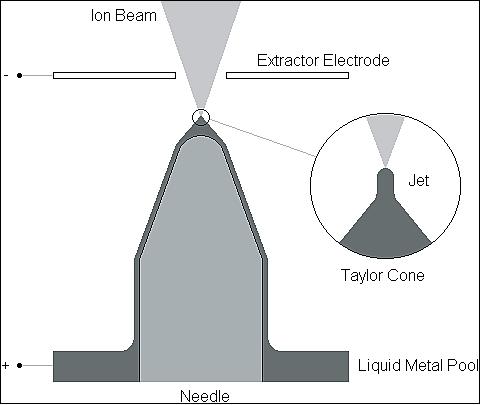
The general working principle of a field emission thruster is illustrated in Figure 11. By applying a high voltage potential between a sharp needle tip, which is wetted with the liquid metal propellant and an extractor electrode, a so called Taylor cone is being generated. This Taylor cone is maintained by the interplay of the liquid metal’s surface tension and the applied electric field. If the electric potential is high enough, an evaporation field strength of about 1010 V/m is reached at the tip of the jet, which sits on top of the Taylor cone, while the liquid metal is being evaporated and ionized. The generated metal ions are being accelerated by the same electric field and exit the extractor electrode. Velocities of more than 100 km/s are possible, depending on the propellant used. With this concept, a very high specific impulse of several thousand seconds and thrusts in the µN range can be achieved.
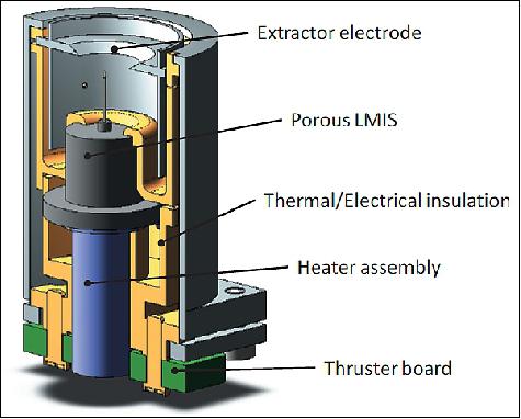
NanoFEEP thruster design: With respect to the limitations of available power and mass on a CubeSat, the main goals in the thruster design were miniaturization and power efficiency. A cut away view of our NanoFEEP module is shown in Figure 12. To achieve a highly efficient and stable ionization, the project uses a novel porous LMIS (Liquid Metal Ion Source), which consists of a very sharp, electrochemically etched porous tungsten needle and a tantalum reservoir filled with the metal propellant. The open porosity of the tungsten needle provides capillary forces, which hold the liquid metal propellant at the needle tip, and enables self-feeding propellant flow during operation. Thus, no valves or propellant feeding devices are required. The porous LMIS is heated up by the heater assembly and is supported by thermal and electrical insulation, whose shape is optimized by thermal simulations to minimize thermal losses.
With this thermal optimization of the thruster geometry, only 50 to 90 mW of heating power (depending on satellite structure temperature) are necessary to keep the propellant liquid at a temperature of 50°C. Furthermore, Gallium with its low melting temperature of approximately 30°C is used as propellant to keep down the power demand for melting the propellant compared to commonly used propellants, like Indium with a melting temperature of 157°C.
To avoid short circuits between the LMIS on high voltage potential and the extractor electrode during long term operation, the NanoFEEP module features labyrinth shielding. Thus, possible surface contamination of the inner insulation structure with the electrically conductive propellant caused by micro-droplets will not affect long-term operation. The major reason for the given limit of operating time of approximately 1,800 h is due to the used amount of propellant (0.25 g Gallium per thruster). This maximum operation time is thought to be sufficient for the first precursor mission, but it can be enhanced easily in future missions by using larger reservoirs of the LMIS. Though, the dimensions of the thruster would need to be adjusted in that case.
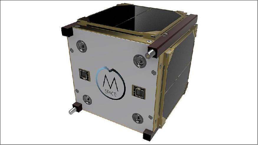
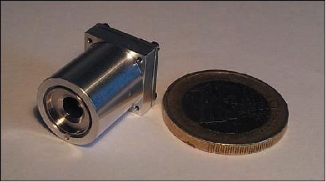
With this NanoFEEP design, a field emission thruster could be miniaturized down to Ø13 x 21 mm with a total mass of less than 6 g and a volume of less than 3cm3 per thruster. Figure 3 shows one manufactured NanoFEEP thruster compared to a one Euro coin to visualize the thruster size. A further miniaturization of the thruster is currently under investigation as saving only a few millimeters in size would strongly simplify the thruster integration in a 1U CubeSat.
Thruster performance: First tests were performed to determine the functionality of the miniaturized thruster design and to roughly characterize the thruster performance. A stable operation of the thruster with the novel porous LMIS running with Gallium propellant could be demonstrated.
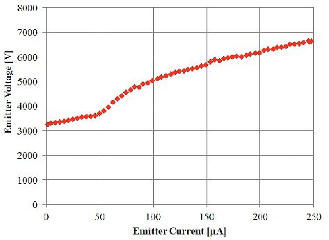
A typical current-voltage characteristic (beginning of life) of a NanoFEEP thruster is shown in Figure 14. The NanoFEEP typically starts operating at a voltage between 3.3 and 4 kV. The starting voltage increases with operation time to approximately 6 to 7 kV while the slope of the current-voltage characteristic, in other words the impedance, decreases. Considering this typical behavior of FEEP thrusters with needle emitters and adding a safety margin to the required voltage range, a high voltage demand of 12 kV is defined as maximum for the required power processing unit. NanoFEEP was tested up to an emission current of 250 µA which corresponds to a thrust of approximately 22 µN without any problems. This emission current limit of 250 µA is due to the specified maximum available output current of the high voltage converter which shall be used on the CubeSat platform. However, a maximum emission current of 100 µA, corresponding to a thrust of approximately 8 µN, is recommended for long-term operation (more than a hundred hours) to prevent needle erosion.
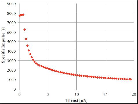
Additionally, tests were performed to determine the mass efficiency of the novel porous needle LMIS with Gallium propellant used in the NanoFEEP thrusters. During these mass efficiency tests, the LMIS was operating at different constant emission currents and was weighed before and after each test run. The mass efficiency was then calculated by comparing the exhausted charge to the mass difference. The calculated mass efficiency showed the typical exponential decline with increasing emission currents. This decline is due to the increasing amount of unionized droplets at higher emission currents. For calculating the specific impulse of NanoFEEP as a function of thrust, shown in Figure 15, the described mass efficiency as a function of emission current was used. This is the reason for the decline in specific impulse for higher emission currents which can be seen in Figure 15.
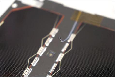
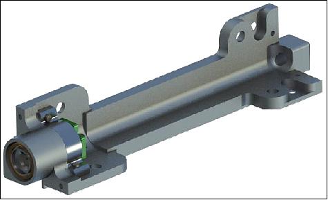
The NanoFEEP system, developed at TU Dresden, was selected for its compatibility with the 1U size and power restrictions. The system consists of the thruster heads and two dedicated PPUs (Power Processing Units). The thruster heads have been integrated into the CubeSat bars as shown in Figure 16, while the PPUs are designed as standard subsystems for the UNISEC Europe bus.
The thrust is generated through ionization and subsequent acceleration of small amounts of Gallium fuel. The fuel is stored in the thruster heads (0.25 g each) and is heated to a temperature of about 50°C at which the Gallium is liquid and flows due to capillary forces along the porous needle to its tip. An electric voltage of up to 12 kV between the needle and the extractor cathode ejects the ions from the thruster by electrostatic force. The required voltage is generated from the unregulated battery voltage on one of the two PPUs which can provide up to 250 µA of current. Each PPU can interface and power two thruster heads and one neutralizer individually. A single thruster can generate continuously a thrust level of up to 8 µN with peaks up to 20 µN and requires approximately 700 mW at 2 µN thrust.
Laboratory tests with a PPU prototype have shown its capability of providing the necessary power in the main operation regime of up to 6.5 kV and 2 W from the satellite’s EPS with a battery voltage of about 4.0 V. A new set of thruster heads are currently being integrated at TU Dresden together with minor revisions of the PPU. Long term operation and full integrated EMC compatibility tests are planned in the future.
Besides its application in the field of formation flying of CubeSats, this flexible and modular propulsion system could in the future be used for precise attitude control and orbit maintenance of lower Earth orbits.
References
1) P. Bangert, S. Dombrovski, A. Kramer, K. Schilling. “UWE-4: Advances in the Attitude and Orbit Control of a Pico-Satellite.” Proceedings of Small Satellites Systems and Services - The 4S Symposium, Valetta, Malta, 2016
2) Klaus Schilling, ”The UWE-Roadmap to Pico-Satellite Formation Flying: In-Orbit Experiences,” Proceedings of the 29th Annual AIAA/USU Conference on Small Satellites, Logan, Utah, USA, August 8-13, 2015, URL: http://digitalcommons.usu.edu/smallsat/2015/all2015/104/
3) D. Bock, M. Bethge, M. Tajmar. “Highly miniaturized FEEP thrusters for CubeSat applications,“ Proceedings of the 4th Spacecraft Propulsion Conference. Cologne, Germany, May 2014, URL: https://www.researchgate.net/publication
/280883495_Highly_Miniaturized_FEEP_Thrusters_for_CubeSat_Applications
4) ”CubeSat Subsystem Interface Definition,” UNISEC Europe, Version 0.4, 21.07.2015, URL: https://web.archive.org/web/20180517013941/http://unisec-europe.eu:80/wordpress/wp-content/uploads/CubeSat-Subsystem-Interface-Standard-1.pdf
5) Philip Bangert, Alexander Kramer, Klaus Schilling, ”UWE-4: Integration State of the First Electrically Propelled 1U CubeSat,” Proceedings of the 31st Annual AIAA/USU Conference on Small Satellites, Logan UT, USA, Aug. 5-10, 2017, paper: SSC17-WK-47 (Pre-Workshop Session 3: Propulsion), URL: http://digitalcommons.usu.edu/cgi/viewcontent.cgi?article=3546&context=smallsat
6) Stephen Clark, ”Soyuz launches cluster of 28 satellites,” Spaceflight Now, 27 December 2018, URL: https://spaceflightnow.com/2018/12/27/soyuz-28-satellite-cluster-launch/
7) Anatoly Zak, ”Soyuz rocket launches a 28-satellite cluster,” Russian Spaceweb, 27 December 2018, URL: http://www.russianspaceweb.com/kanopus-v5-v6.html
8) ”UWE4 launch successful, first beacons received!,” University of Würzburg, 27 December 2018, URL: http://www7.informatik.uni-wuerzburg.de/forschung/space-exploration/projects
/uwe-4/news/single-news/news/uwe4-launch-successful-first-beacons-received/
9) Alexander Kramer, Philip Bangert, Klaus Schilling, ”Hybrid attitude control on-board UWE-4 using magnetorquers and the electric propulsion system NanoFEEP,” Proceedings of the 33rd Annual AIAA/USU Conference on Small Satellites, August 3-8, 2019, Logan, UT, USA, paper: SSC19-WKI-02, URL: https://digitalcommons.usu.edu/cgi/viewcontent.cgi?article=4351&context=smallsat
10) ”Morpheus Space qualifies the world's smallest satellite propulsion system in orbit,” Space Daily, 27 February 2019, URL: http://www.spacedaily.com/reports/SusMorpheus_Space_
qualifies_the_worlds_smallest_satellite_propulsion_system_in_orbit_999.html
11) http://morpheus-space.com/
12) ”MORPHEUS: Cutting-edge spacecraft propulsion,” ESA Technology Transfer, 25 January 2019, URL: http://m.esa.int/Our_Activities/Space_Engineering_Technology
/TTP2/MORPHEUS_Cutting-edge_spacecraft_propulsion
13) Daniel Bock, Alexander Kramer, Philip Bangert, Klaus Schilling, ”NanoFEEP on UWE platform -Formation Flying of CubeSats using Miniaturized Field Emission Electric Propulsion Thrusters,” IEPC-2015-121/ISTS-2015-b-121, Joint Conference of 30th International Symposium on Space Technology and Science 34th International Electric Propulsion Conference and 6th Nano-satellite Symposium, Hyogo-Kobe, Japan, July 4 – 10, 2015, URL: http://erps.spacegrant.org/uploads
/images/2015Presentations/IEPC-2015-121_ISTS-2015-b-121.pdf
The information compiled and edited in this article was provided by Herbert J. Kramer from his documentation of: ”Observation of the Earth and Its Environment: Survey of Missions and Sensors” (Springer Verlag) as well as many other sources after the publication of the 4th edition in 2002. - Comments and corrections to this article are always welcome for further updates (eoportal@symbios.space).
Spacecraft Launch Mission Status Experiment References Back to Top