UniCubeSat-GG
Non-EO
Quick facts
Overview
| Mission type | Non-EO |
| Launch date | 13 Feb 2012 |
| End of life date | Mar 2012 |
UniCubeSat-GG (Gravity Gradient)
UniCubeSat-GG is the first CubeSat mission of GAUSS (Gruppo di Astrodinamica dell' Universita degli Studi “la Sapienza”) at the University of Rome (Universita di Roma “La Sapienza”, Scuola di Ingegneria Aerospaziale), Italy. The overall objective is to provide hands-on education for students, reducing the satellite mass from 10 kg (UNISAT series) to 1 kg (CubeSat series).
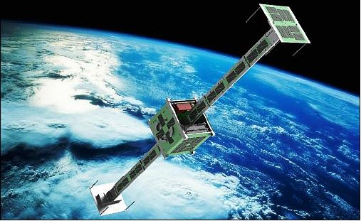
Its main payload concerns the study of the gravity gradient enhanced by the presence of a deployable boom. The end faces of the boom are equipped with solar panels for added power generation. 1) 2) 3) 4)
Note: The initial mission objective of “in situ atmospheric neutral density measurements in the thermosphere using the Broglio drag balance instrument as payload” was changed in favor of a boom implementation involving the study of a passive attitude control technique, based on gravity gradient stabilization.
Spacecraft
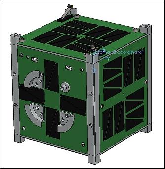
UniCubeSat-GG is a CubeSat shaped satellite with external dimensions of 10 cm x 10 cm x 13.5 cm. The external dimensions follow the requirements of the CubeSat Design Specifications document. The CubeSat has a mass of 1 kg.
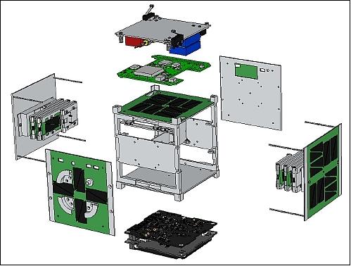
The typical CubeSat structure is modified in order to board the main payload: a boom for gravity gradient stabilization. The structure is made of aluminum 6061-T6. The critical items in the mechanical and structural subsystem design are antennas and boom deployments. Both system will be deployed using thermal cutters. The satellite electronics subsystems are based on commercial off the shelf components (COTS).
ADCS (Attitude Determination and Control subsystem): The ADCS is designed to determine and analyze the attitude of the deployed boom system. No detumbling system is foreseen. Attitude measurements are provided by two magnetometers and by the telemetry of the solar panels. Attitude determination will be performed on ground, once attitude data from the magnetometer are downloaded. The employed state estimation algorithm is the Unscented Filter Method, which is more suitable for a nonlinear problem of the satellite attitude motion, rather than the common Extended Kalman Filter.
EPS (Electric Power Subsystem): The EPS is based on space rated TJ (Triple Junction) solar cells and Li-polymer batteries. Use of a TASC (Triangular Advanced Solar Cell) system design manufactured by Spectrolab. These solar cells are put on each panel in four arrays of four cells. In order to increase the power generated by the solar cells, each boom panel is equipped with T four cell on every side. The average power per orbit is ~ 4 W.
Power storage is provided by a space qualified lithium-polymer battery assembly of ClydeSpace (3.4 Ah capacity). The power management and protection task is carried out by the Clyde Space EPS board. The EPS board can interface many solar arrays and integrate active solar array maximum power point tracking. It also protects the battery from under-voltage.
All batteries have integrated over current protection. This is achieved by using polyswitches which are designed to trip whenever an over-current event occurs. To protect the battery and satellite from power faults, such as over current or under voltage, a monitoring and shutdown system is required. The system must be able to detect and shutdown any power line which has encountered a fault. - The loss of one pair of cells, (i.e. one battery in the stack) will not affect the performance of the remaining batteries – power will continue to be supplied to the system.
OBDH (On Board Data Handling and Communications) subsystem: The OBDH is comprised of a specifically designed PCB (Printed Circuit Board) which hosts the microcontroller and the other circuits needed for data storage, communication, conversions, timing and execution of the tasks..
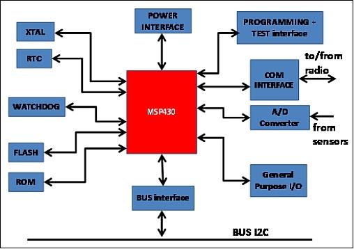
The core of the OBDH subsystem is the MCU (Microcontroller Unit) from Texas Instruments' MSP430 family. This is a 16 bit RISC (Reduced Instruction Set Computer) system with internal RAM and FLASH memory which is used as mass memory storage for telemetry data. The digital sensors are connected to the MCU using an I2C bus interface with the MCU acting as unique Master, the sensors are connected as slaves. Up to two UART (Universal Asynchronous Receiver/Transmitter) communication ports can be reserved to use with payload modules for the Wi-Fi (Wireless Fidelity) communication experiment.
The OBDH subsystem is powered by the Clyde Space's CS-3UEPS2-NB Board Power Bus. The OBDH board is equipped with internal voltage regulators in order to provide a stable 3.3 V to the MSP430 (MCU).
TCS (Thermal Control Subsystem): The TCS is completely passive. The spacecraft can operate in the temperature range of -25ºC to +85ºC.
RF communications: The S/C communications conform to amateur radio standards in UHF band (437.305 MHz) permitting a data rate of 9.6 kbit/s full duplex communications (a COTS radio is used). Use of the AX.25 2.0 communications protocol; the modulation is: FSK/GSSK. In addition, one beacon is used.
Launch
The UniCubeSat satellite was launched on Feb. 13, 2012 as a secondary payload on the maiden flight of the Vega launch vehicle of ASI and ESA. The launch site was Kourou in French Guiana. 5) 6)
The multiple payload launch encompasses a primary payload of 400 kg called LARES (LAser RElativity Satellite), and CubeSats (educational payloads) as secondary payloads, whose launch is sponsored by ESA. The free launch of CubeSats was offered by the ESA Education Office in Oct. 2007 (Announcement Opportunity) in cooperation with the Vega program. 7)
CubeSat passenger payloads: Although ESA's Education Office is providing 9 CubeSat positions on the maiden flight of Vega, only 7 CubeSats are confirmed as of December 2011 (Ref. 8). Not all universities that were preselected for the launch opportunity in June 2008, were able to deliver their CubeSat and the requested documentation. Other CubeSat projects, like SwissCube and HiNCube, decided to be launched on commercial flights.
Secondary Payloads
• Xatcobeo (a collaboration of the University of Vigo and INTA, Spain): a mission to demonstrate software-defined radio and solar panel deployment
• Robusta (University of Montpellier 2, France): a mission to test and evaluate radiation effects (low dose rate) on bipolar transistor electronic components
• e-st@r (Politecnico di Torino, Italy): demonstration of an active 3-axis Attitude Determination and Control system including an inertial measurement unit
• Goliat (University of Bucharest, Romania): imaging of the Earth surface using a digital camera and in-situ measurement of radiation dose and micrometeoroid flux
• PW-Sat (Warsaw University of Technology, Poland): a mission to test a deployable atmospheric drag augmentation device for de-orbiting CubeSats
• MaSat-1 (Budapest University of Technology and Economics, Hungary): a mission to demonstrate various spacecraft avionics, including a power conditioning system, transceiver and on-board data handling.
• UniCubeSat GG (Universitá di Roma ‘La Sapienza’, Italy): the main mission payload concerns the study of the gravity gradient (GG) enhanced by the presence of a deployable boom.
ALMASat, a microsatellite of the University of Bologna, is another secondary payload of the flight.
Use of P-POD (Poly Picosat Orbital Deployer) for the deployment of all CubeSats.
Orbit of secondary payloads: Elliptical orbit, altitude of 354 km x 1450 km, inclination = 69.5º, orbital period = 103 minutes (14 revolutions/day). About 75% of the orbit is in sunlight.
Mission Status
• The UniCubeSat-GG transmitted data for about 1-2 weeks after the launch. The project didn't try to recontact the spacecraft after the third week. Possible reasons for the short mission life could be: 10)
- the orbit: inside the Van Allen belts, the project didn't design a good protection system because the goal was to board a boom, a powered boom. And the room was not enough to board other components
- the batteries: one battery package didn't survive to the environmental tests before the launch
- the thermal environment: some unofficial information reported about more than 100ºC reached by the Vega vehicle prior to the CubeSat release.
• March 2012: The CubeSat seems to be tumbling very rapidly and re-establishing communications which might turn out to be very difficult. 11)
• The UniCubeSat-GG team heard the first signals from the satellite shortly after launch, first from a Kentucky (US) ground station and then from the dedicated Rome ground station. The team is now waiting for the next ground passes to receive clearer signals and get actual information about the status of the satellite. 12)
Sensor Complement
The primary payload of UniCubeSat is the in orbit test of the gravity gradient attitude stabilization system. This is why it is referred to as the UniCubeSat-GG (Gravity Gradient).
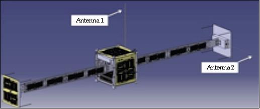
The design features two symmetrical booms that unfold from the geometric center of the satellite to the outside. A small box is installed on the tips of both rigid arms. In the deployed configuration, the distance between the two tip masses is about 1 m.
Gravity gradient discussion: In the early days of the space missions, the gravity gradient effect was used for attitude stabilization: a stable equilibrium is generated when the spacecraft with its minimum inertia axis is pointing toward Earth (nadir), while the axis of maximum inertia is pointing in the zenith direction (normal to the orbital plane). - However, in the process of acquisition of such an equilibrium state, it is difficult to avoid some residual energy which produces librations of ~ 5º about the equilibrium position.
In some cases, the requirements in axis pointing accuracy are less stringent and the conventional gravity gradient stabilization looks rather attractive because of its low cost; hence, this configuration has been successfully used for low-cost attitude control microsatellites in near-circular LEO missions.
For elliptic orbits, as is the case of the UniCubeSat mission, the gravity field depends on the position of the spacecraft on its orbit. As a result, the system is not autonomous anymore and there is no equilibrium position. However, the existence of planar periodic librations of small amplitude along orbits of small eccentricity (less than 0.2), or along the apogee region of orbits of higher eccentricity, makes in principle the gravity gradient stabilization feasible for eccentric orbits as well. In the case of the UniCubeSat mission, the orbit eccentricity is about 0.07 and the UniCubeSat geometry looks like a dumbbell.
Design and Development of the Boom
The initial UniCubeSat mechanical design has been modified to stabilize the satellite using gravity gradient method. Two symmetrical booms have been added to the previous design which unfold from the geometric center of the satellite to the outside. A small box is installed on the tips of both rigid arms. In the deployed configuration, the distance between the two tip masses is about 878 mm (Figure 5).
The design and manufacturing of a boom for gravity gradient stabilization poses some critical issues, in particular due to the deployment system and the boom rigidity after the deployment. In the case of a gravity boom for a CubeSat, the difficulties are considerable considering the small volume available inside the structure for the boom in stowed configuration.
The adopted boom system within the CubeSat uses deployable plates connected by hinges with a torsion system. On orbit deployment, these surfaces unfold simultaneously in opposite directions, giving limited disturbances to the satellite attitude.
During the design of the deployable system, different configurations and materials have been taken into account, but the final configuration and the use of stainless steel hinges with torsional spring is the one that allows a safe deployment.
The choice of spring hinges with a range of motion of 270º allows to completely deploy the boom elements and at the same time to have a residual torque that does not allow the system to fall back. Moreover, the use of fiberglass plates as central booms element allows to increase the external surfaces available for the use of photovoltaic energy production.
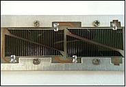
Thanks to the use of a pre-coated photoresistive fiberglass board as central element of each boom plate, it is possible to glue solar cells directly to the boom panels using special conductive glue.
In particular, each outside of the two boom panels is an electronic board equipped with 4 solar TASC cells and able to provide a maximum power of 0.24 W at 9 V. After on-orbit deployment of the booms, the plates are blocked forming a plane surface. In this way, a surplus area is obtained of about 30 cm2 on each side, available to produce additional energy using solar cells.
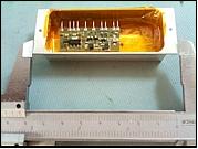
The booms open outside the satellite, taking with them two opposite faces of the CubeSat. It is possible to install further subsystems or payloads on both ends of the deployed system; for example, a small transmitter is installed inside of one of the two tip masses - capable to send a beacon signal to GAUSS ground station. The other tip mass uses an Arduino microcontroller, able to command the beacon transmitter on the other face. The connections between the beacon and the microcontroller are provided using wire connections.
References
1) Chantal Cappelletti, Giuseppe Martinotti, Filippo Graziani, “UniCubeSat: a test for the Gravity-Gradient Solar Array Boom,” Proceedings of IAC 2011 (62nd International Astronautical Congress), Cape Town, South Africa, Oct. 3-7, 2011, paper: IAC-11-B4-6B.12
2) Information (User Manual of UniCubeSat-GG) provided by Chantal Cappelletti of GAUSS at University of Rome Sapienza
3) Filippo Graziani, Fabio Santoni, Fabrizio Piergentili, Maria Libera Battagliere, Francesco Guarducci, Fabrizio Paolillo, Luigi Ridolfi, Chantal Cappelletti, “UniCubeSat,” CubeSat Developers' Workshop, CalPoly, San Luis Obispo, CA, USA, April 22-25, 2009, URL: https://web.archive.org/web/20151203124533/http://mstl.atl.calpoly.edu:80/~bklofas/Presentations/DevelopersWorkshop2009/2_Science/3_Santonio-UNICubeSat.pdf
4) Fabio Santoni, Fabrizio Piergentili, Filippo Graziani, “UniCubeSat: a satellite for aeronomy measurements in orbit,” Proceedings of the 60th IAC (International Astronautical Congress), Daejeon, Korea, Oct. 12-16, 2009, IAC-09.D1.1.11
5) “ESA’s new Vega launcher scores success on maiden flight,” ESA, Feb. 13, 2012, URL: http://www.esa.int/SPECIALS/Vega/SEMJ8LYXHYG_0.html
6) “Vega VV01 launch campaign,” ESA, URL: http://www.esa.int/SPECIALS/Vega/SEMY64BX9WG_mg_1.html
7) Jakob Fromm Pedersen, “CubeSat Educational Payload on the Vega Maiden Flight, Interface Control Document,” ESA/ESTEC, Feb. 13, 2009
8) “ESA’s CubeSats ready for flight,” ESA, Dec. 16, 2011, URL: http://www.esa.int/SPECIALS/Education/SEMG1C8XZVG_0.html
9) “ESA Cubs delivered for first Vega flight,” ESA, Nov. 14, 2011, URL: http://www.esa.int/esaMI/Education/SEM3L0WWVUG_0.html
10) Information provided by Chantal Cappelletti, GAUSS Team, University of Rome (La Sapienza), Italy.
11) “CubeSats satellite operations update,” ESA, March 28, 2012, URL: http://www.esa.int/SPECIALS/Education/SEM2KRGY50H_0.html
12) “Student CubeSats start talking to Earth,” ESA, Feb. 14, 2012, URL: http://www.esa.int/SPECIALS/Education/SEMR2ZYXHYG_0.html
The information compiled and edited in this article was provided by Herbert J. Kramer from his documentation of: ”Observation of the Earth and Its Environment: Survey of Missions and Sensors” (Springer Verlag) as well as many other sources after the publication of the 4th edition in 2002. - Comments and corrections to this article are always welcome for further updates (eoportal@symbios.space).