Ulysses Minisatellite
Non-EO
ESA
NASA
Quick facts
Overview
| Mission type | Non-EO |
| Agency | ESA, NASA |
| Launch date | 06 Oct 1990 |
| End of life date | 30 Jun 2009 |
Ulysses
Spacecraft Launch Mission Status Sensor Complement References
Ulysses is a joint interplanetary minisatellite mission of ESA and NASA. The overall objective of Ulysses is to explore the sun's polar regions (first-ever study of the particles and fields in the inner heliosphere at all solar latitudes, including the polar regions). Particular emphasis is on the study of the solar wind, the interplanetary magnetic field, and the complex wave and particle interaction phenomena that exist in the interplanetary medium. Naturally there is international collaboration and coordination of the Ulysses mission with other ISTP projects like: INTERBALL, SOHO, WIND, Solar-A (Yohkoh), STEREO, and SOLAR-B (Hinode). 1) 2) 3) 4) 5) 6) 7) 8) 9)
Background: ESA and NASA studied the possibility of an "out-of-ecliptic" (OOE) mission in the early 1970s. The mission would consist of two spacecraft flying in formation out to Jupiter and then one of them heading for the northern region of the sun and the other for the southern region. Two spacecraft at opposite poles from each other would be able to almost completely map the sun.
The mission, which was eventually referred to as ISPM (International Solar-Polar Mission), was approved in 1976, the payload approved in 1977, and a provisional launch date set for February 1983. By 1980, NASA experienced considerable budgetary problems in its planetary space program which resulted in the elimination of the second spacecraft in ISPM. However, ESA decided to go ahead with a single-spacecraft version of the mission, using a European spacecraft with half the instruments on board from the United States. In 1984, the ISPM mission was given its final name `Ulysses'.
The Ulysses mission was planned for a launch on the Space Shuttle in May 1986. However, the big Challenger accident on January 28, 1986 at KSC (Kennedy Space Center) put an immediate halt to all further Shuttle launches until 1989. The Ulysses mission was given a new launch opportunity for the fall of 1990 (a 4-year delay from the previous launch date).
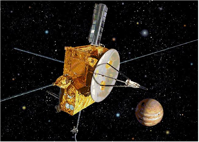
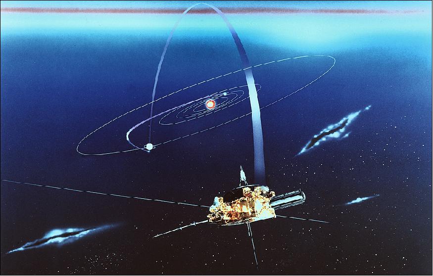
Spacecraft
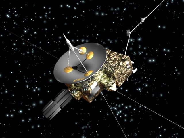
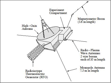
The structure of the Ulysses spacecraft is a box-shaped aluminum bus. The central box features a honeycomb structure of size: 2 m x 2 m x 1 m. The S/C is spin-stabilized at 5 rpm; a high-gain communication antenna (HGA) with a 1.65 m diameter parabolic dish is mounted onto the spin axis; the dish is pointing toward Earth continuously. The Earth-pointing HGA provides the communication link to Earth.
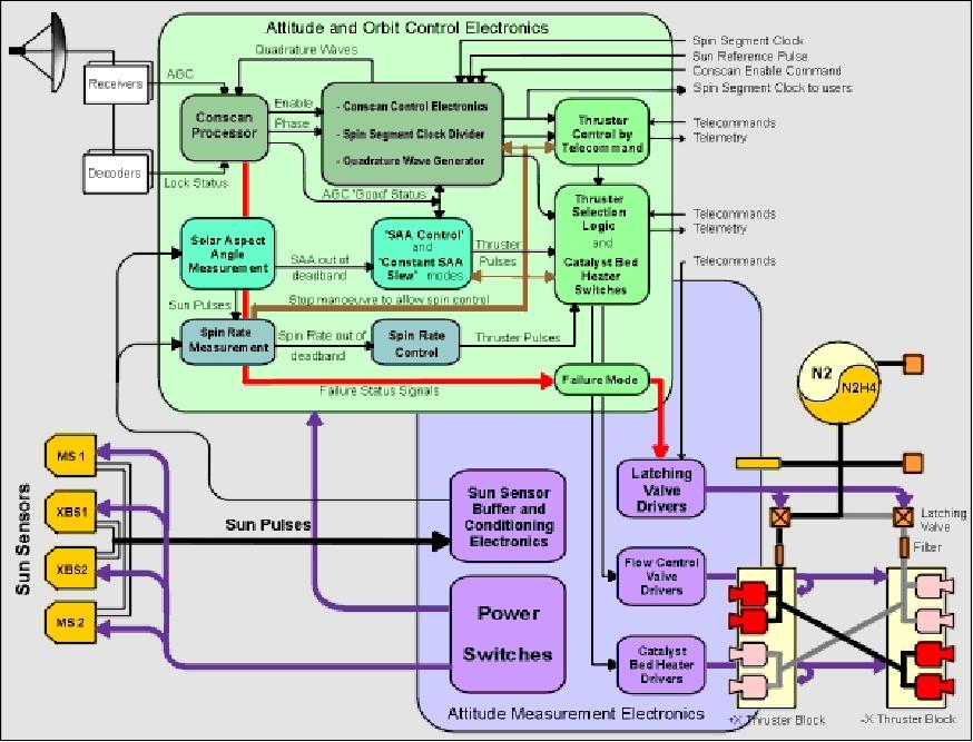
The AOCS (Attitude and Orbit Control Subsystem) is comprised of the redundant sun-sensor system: the AOCE (Attitude and Orbit Control Electronics), the AME (Attitude Measurement Electronics) and the RCE (Reaction Control Equipment). The primary operational functions of the AOCS are to maintain the spacecraft spin axis Earth-pointing and to control the spin rate. Two sets of 4 x 2 N hydrazine thrusters (33 kg of propellant) provide spin control and trajectory corrections. 10) 11)
Electrical power for the deep space mission is provided by the RTG (Radio-isotope Thermoelectric Generator) system, with 285 W at start and 244 W at the end of the first solar cycle. The RTG power sources are being used in environments (in particular in deep space missions) where the solar radiation becomes ineffective for a S/C power subsystem, namely at vast distances from the sun. RTGs provide power through the natural radioactive decay of plutonium (mostly Pu 238, a non-weapons-grade isotope). The heat generated by this natural process is changed into electricity by solid-state thermoelectric converters. The RTG system was provided by NASA (ESA did not develop this type of power generation technology for deep space missions).
The S/C is thermally controlled by passive means (radiators, thermal paints, and thermal blankets) and by heaters. S/C total mass of 370 kg, mass of science payload = 55 kg. Booms: radial dipole antenna of 72.5 m length, axial monopole antenna of 7.5 m length, and a radial magnetometer boom of 5.6 m length. The boom is made from carbon-fiber-reinforced plastic (CFRP) tubing 50 mm in diameter and with 1 mm wall thickness.
Major contributions to the Ulysses mission: ESA [funding of S/C, S/C operations, 50% of experiments by ESA member states]; NASA [funding of S/C launch, provision of RTG, use of DSN (Deep Space Network) and JPL control center, 50% of experiments]. The S/C was built by an industrial consortium with Dornier System (Friedrichshafen, Germany) as the prime contractor (thereafter EADS Astrium GmbH, now Airbus DS).
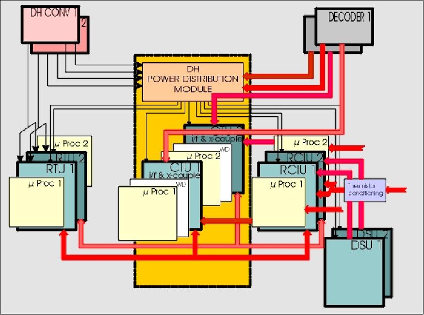
The DHS (Data Handling System) provides all TT&C services in support of data transmissions and onboard processing functions. The DHS uses a microprocessor system with a special purpose software package designed for Ulysses operations.
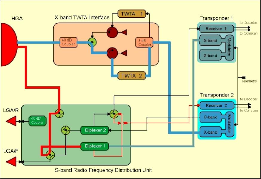
RF communications: X-band downlink (20 W, 8.4 GHz frequency) and S-band uplink/downlink (5 W, 2112 MHz uplink and 2293 MHz downlink). Telemetry data at 1.024 kbit/s (real-time) and at 512 bit/s of storage data. Two redundant tape recorders have a capacity of 45.8 Mbit each. Ulysses is tracked 8 hours/day by the 34 m antennas of NASA's Deep Space Network. The mission operations are supported by a joint ESA/NASA team at NASA/JPL.
Ulysses introduced a special "orientation feature" in its communication system which deviates from other interplanetary probes so far. The S-band antenna direction deviates from the S/C rotational axis by 1.8º - generating a modulation in the uplink signals. The autonomous onboard processing of the modulated S-band signal permits the direct determination of the spin axis orientation as well as the spin rate. The transmit signals of the HGA (High Gain Antenna) in S-band have a cone width of 10º (@ -3 dB), and 2º in X-band.
Launch
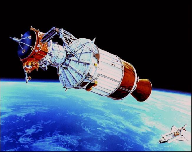
The Ulysses spacecraft along with the Inertial Upper Stage (IUS) was launched on the Shuttle mission STS-41 (Discovery), October 6, 1990, from Cape Canaveral, Florida.
A two-stage IUS (Inertial Upper Stage) and a mission-specific PAM (Payload Assist Module) combined together to send Ulysses toward its out-of-ecliptic trajectory. To reach this out-of-ecliptic trajectory, Ulysses was sent out to the planet Jupiter, whose immense gravity was used to deflect the spacecraft in a slingshot fashion into a highly inclined orbit (80º inclined to the ecliptic). 12)
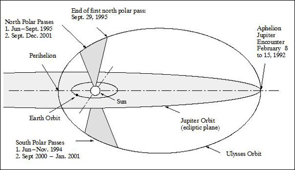
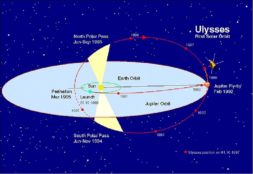
Orbit: The Ulysses probe is the first S/C having left the ecliptic plane of the solar system to observe the poles of the sun. The orbital change into a normal plane to the ecliptic was achieved with a sling-shot flyby, a gravity-assist maneuver, of Jupiter (Feb. 8, 1992).
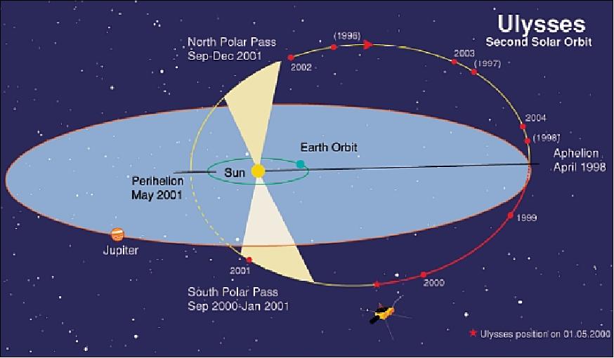
The S/C operates at heliocentric ranges which vary between 1.34 and 5.4 AU (where the solar flux varies between 1400 Wm-2 and 45 Wm-2) inclined at 80.2º to the ecliptic. The portions of the orbit when Ulysses is above 70º solar latitude have been designated as "polar passes." The first such polar pass occurred in 1994 (south) and 1995 (north). The S/C takes 6.2 years to complete one orbit around the sun. The second set of polar passes took place from Sept. 2000 to Jan. 2001 (south) and Sept. to Dec. 2001 (north). 13) 14) 15)
Mission Status
• February 8, 2017: 25 Years ago as of today, the Solar Probe Ulysses got a gravity assist from Jupiter to leave the ecliptic plane to explore the "never seen before" poles of the Sun. After sixteen months of interplanetary cruise, the Solar Probe Ulysses of ESA/NASA arrived on 8 February 1992 at Jupiter, the Solar System's largest planet. A Jupiter gravity-assist was used to place the spacecraft, built by Airbus, in its unique trajectory which took the probe into the previously unexplored third dimension of the heliosphere. Ulysses surveyed the environment above and below the poles of the Sun. 17)
- In the course of its 17.5 year mission, Ulysses showed - among other results - that the heliospheric magnetic field is more complicated than had been thought. Ulysses also observed the solar wind in four dimensions, and showed that energetic particles are present at all phases of a solar cycle, it detected dust particles of interstellar origin and directly measured the properties of interstellar gas for the first time.
• October 19, 2015: In the early 1990s, contemporary interstellar dust penetrating deep into the heliosphere was identified with the in situ dust detector on board the Ulysses spacecraft. Between 1992 and the end of 2007 Ulysses monitored the interstellar dust stream. The interstellar grains act as tracers of the physical conditions in the local interstellar medium (ISM) surrounding our solar system. Earlier analyses of the Ulysses interstellar dust data measured between 1992 and 1998 implied the existence of a population of "big" interstellar grains (up to 10-13 kg). The derived gas-to-dust-mass ratio was smaller than the one derived from astronomical observations, implying a concentration of interstellar dust in the very local ISM. In this paper we analyze the entire data set from 16 years of Ulysses interstellar dust measurements in interplanetary space. 18)
• On June 30, 2009, the Ulysses spacecraft received the last command from ground control, switching the transmitter off for the last time. The joint ESA/NASA mission operations team under Nigel Angold, ESA Mission Operations Manager, monitored the final activity from the Ulysses Mission Support Area (MSA) at NASA's Jet Propulsion Laboratory (JPL), California, USA (Ref. 8). 19) 20)
In short, the mission has lasted for 18 1/2 years and has forever changed the way scientists view the Sun and its effect on the surrounding space. 21)
Ulysses was the first mission to survey the environment in space above and below the poles of the Sun in the four dimensions of space and time. It showed that the Sun's magnetic field is carried into the Solar System in a more complicated manner than previously envisioned. Particles expelled by the Sun from low latitudes can climb up to high latitudes and vice versa, even unexpectedly finding their way down to planets.
• The Ulysses spacecraft of the joint ESA/NASA mission was officially retired on July 1, 2008 due to the decline in power produced by its on-board generators. — However, operations have continued since then on a day-to-day basis and will continue until the hydrazine fuel eventually freezes or runs out. After a short period earlier in 2009 when the downlink was sufficient to support limited playback of recorded data, the mission was once again in ‘real-time only' mode. Nevertheless, and until decommissioning, the spacecraft continues to return useful science data. These data are proving very useful in the study of long-term variations in cosmic-ray transportation in the heliosphere, in particular the Anomalous Cosmic Ray (ACR) component. 22)
• The X-band downlink of Ulysses failed in January 2008. Numerous attempts were made to re-establish the downlink, but they remained without any success. An S-band science mission was defined to circumvent the dead X-band link. However, by May 2008, the S-band downlink had deteriorated due to the the increasing distance between the spacecraft and Earth to the point that playback of recorded data could no longer be supported and only spacecraft data received in real-time during a tracking pass could now be acquired. As a result of these and other operational measures, the projected mission end date of 1 July 2008 was reached without the hydrazine freezing. Spacecraft operations and science data acquisition will continue using the same strategy until freezing occurs. 23)
• The spacecraft has been operating nominally for most of its mission (17 years in orbit as of Oct. 2007). Although originally designed for a mission lasting 5 years, the Ulysses space probe and its suite of 9 scientific experiments are still going strong (in early 2008) after more than 17 years in orbit. Operating the spacecraft has become more demanding over the years, however, as one consequence of the mission's longevity is a decrease in the electrical power available on board. 24)
• The mission was originally supposed to end in 1995, but Ulysses was too successful to be retired. NASA and ESA have granted three extensions, most recently in Feb. 2004. Ulysses is scheduled to keep going until 2008, thirteen years longer than originally planned. This latest extension will enable Ulysses to add an important chapter to its survey of the high-latitude heliosphere.
• In Nov. 2007, the ESA Science Program Committee approved a 4th operational extension of the successful Ulysses spacecraft until March 2009. In addition to pursuing its long-term goal of exploring the heliosphere in four dimensions - 3 spatial dimensions and time - Ulysses is a key member of the Heliospheric Network, the international fleet of spacecraft presently operating at many different locations in the heliosphere and beyond. 25)
Parameter | Orbit event | Date |
Launch |
| October 6, 1990 |
Jupiter flyby |
| February 8, 1992 |
1st Aphelion (5.40 AU) |
| February 15, 1992 |
1st polar pass of sun | Start of 1st south polar pass | June 26, 1994 |
1st Perihelion (1.34 AU) |
| March 12, 1995 |
2nd polar pass of sun | Start of 1st north polar pass | June 19, 1995 |
2nd Aphelion (5.41 AU) |
| April 17, 1998 |
3rd polar pass of sun | Start of 2nd south polar pass | September 6, 2000 |
2nd Perihelion (1.34 AU) |
| May 23, 2001 |
4th polar pass of sun | Start of 2nd north polar pass | August 31, 2001 |
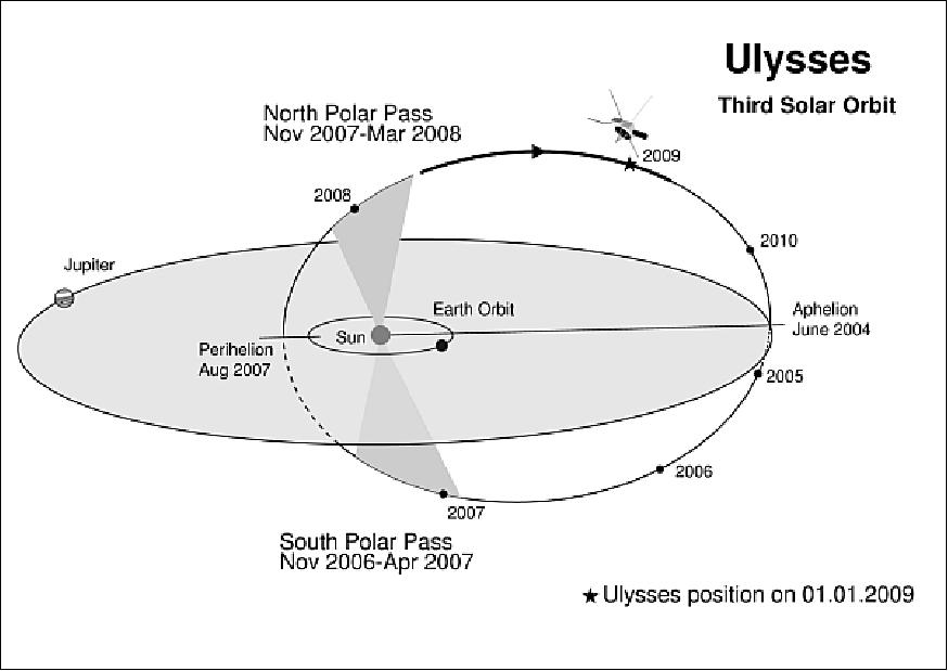
3rd Aphelion (5.41 AU) |
| June 30, 2004 |
5th polar pass of sun | Start of 3rd south polar pass | November 17, 2006 |
3rd Perihelion (1.34 AU) |
| August 18, 2007 |
6th polar pass of sun | Start of 3rd north polar pass | November 30, 2007 |
End of mission |
| June 30, 2009 |
Some scientific accomplishments are:
• Ulysses has conducted the first-ever survey of the sun's environment in space from the equator to the poles, and over a wide range of solar activity conditions.
• Key results to date include the first detailed measurements of the solar wind from the sun's polar regions at solar minimum and solar maximum
• The discovery that the magnetic flux leaving the sun is the same at all latitudes, the discovery of energetic particle "reservoirs" surrounding the sun
• The discovery of interstellar dust in the solar system, and the first direct measurements of interstellar helium atoms in the solar system.
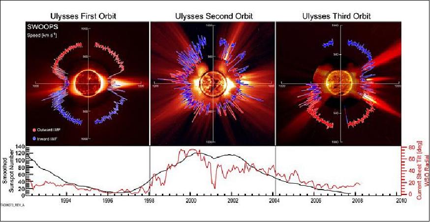
• In 2007 Ulysses started its third north polar pass observing the solar wind and the magnetic field. When the results were compared with Ulysses observations from the previous cycle, the strength of the solar wind pressure and the radial component of the magnetic field embedded in the solar wind were found to have decreased by 20%. The field strength near the spacecraft has decreased by 36%. This reduced state of the sun could reduce the natural shielding that envelops our Solar System. 27)
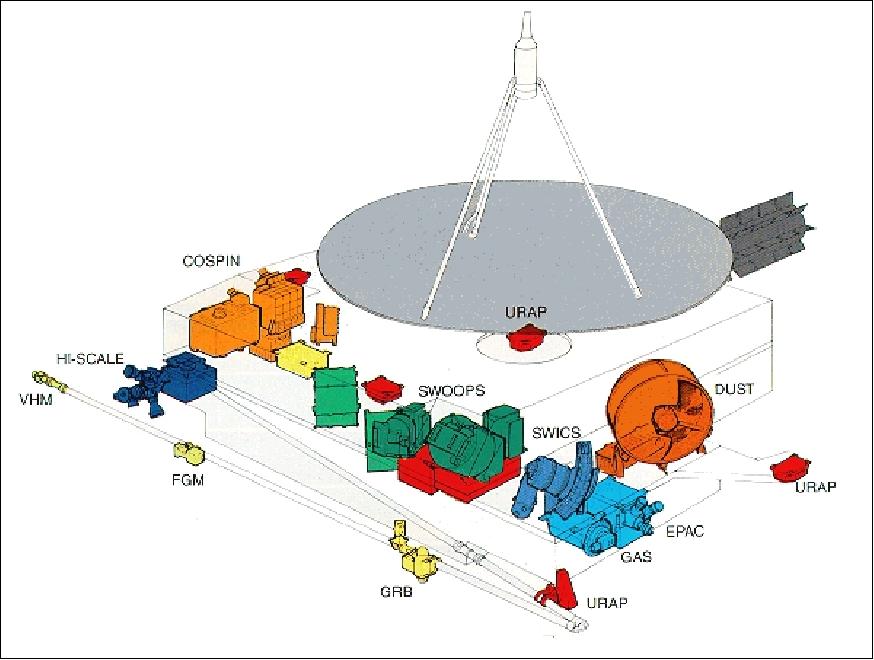
Sensor Complement
The sensor complement of Ulysses has gathered data continuously since launch. Some instruments detect the outward-blowing solar wind and its magnetic field, which create the heliosphere. Others record cosmic rays coming in from the galaxy, which are strongly influenced by the solar wind. Ulysses picks up natural radio signals emitted by the sun, the planets and the heliosphere itself. Innovative techniques can detect foreign atoms and dust particles entering this protective magnetic balloon.
During the first solar orbit, Ulysses data revealed that the gas consists principally of energetic atoms from which one or more electrons have been removed to form ions. These ions become positively charged when they lose their electrons. In addition, three classes of charged particles have been identified on the basis of their energy and place of origin.
COSPIN (Cosmic-ray and Solar Particle Investigation)
PI: J. A. Simpson, U. of Chicago; R. B. McKibben, University of New Hampshire, Durham, NH. Objective: Measurements of solar and interplanetary particles to characterize their intensities, energy spectra, anisotropy and composition as a function of solar latitude. 28) 29)
The instrument comprises five solid-state detector telescopes and a double Cerenkov/semiconductor telescope; energy range = 0.3-600 MeV/n for nuclei and 1-300 MeV for electrons. In addition, one of the telescopes provides measurements of the isotropic composition of galactic cosmic-ray nuclei up to iron (transport of particles). Mass=14.6 kg, power=14.7 W, data rate=160 bit/s. 30)
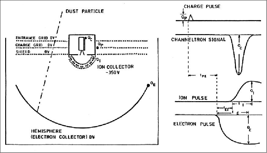
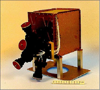
DUST (Dust Experiment)
PI: E. Grün, MPIK, Heidelberg, H. Krueger, MPS, Lindau, Germany. Objective: Measurement of the properties (mass, speed, direction, and electric charge) and distribution of cosmic dust particles in the solar system. The instrument consists of a large hemispherical sensor and a data processing unit. The sensor is made up of a grid system for the measurement of particle charge, an electrically grounded and gold-plated target (hemisphere), and a negatively biased ion collector. Instrument mass=3.8 kg, power=2.2 W, data rate=8 bit/s. 31) 32)
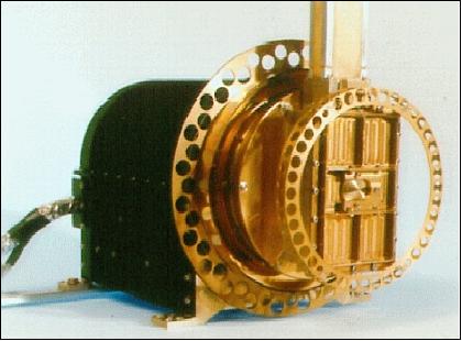
EPAC/GAS (Energetic Particle Composition Experiment/Interstellar Neutral Gas Experiment)
PI: N. Krupp, M. Witte, MPS (Max-Planck Institute for Solar System Research), Katlenburg-Lindau, Germany (note: prior to July 2004 MPS was known as MPAe). Objective: Measurement of the intensities, anisotropies, composition and energy spectra of energetic interplanetary ions in the energy range 0.4-15 MeV/n. Study of the acceleration and transport of low-energy ions of both solar flare and interplanetary origin, with emphasis on their characteristics at high solar latitudes. EPAC consists of a four-telescope detector system. Each telescope contains one epitaxial detector and two surface-barrier detectors. The telescopes are arranged in such a way that between them they cover 80% of a full sphere per S/C spin. 33) 34) 35) 36)
GAS Objective: Direct observations of interstellar neutral helium atoms that have penetrated the heliosphere. Measurement of the parameters (density, bulk velocity relative to the solar system, and temperature) of interstellar gas. The instrument consists of a sensor employing CEM (Channel Electron Multiplier) detector elements. The instrument is mounted on a rotating platform with a scan angle of 180º and is mechanically attached to an electronics box. Total mass=4.3 kg, power=4.1 W, data rate=16 bit/s. 37) 38)
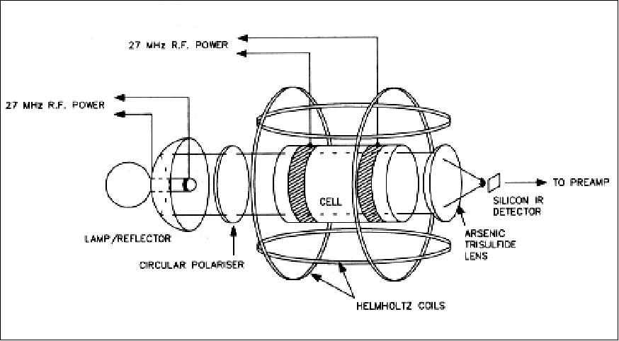
FGM/VHM (Fluxgate Magnetometer/Vector Helium Magnetometer)
PI: A. Balogh, Imperial College, London, UK. Objective: In-situ observations of the helio-latitude dependence of the interplanetary magnetic field (structure, characteristics, topology, dynamic properties, etc.). Both magnetometers are boom-mounted to eliminate the magnetic effects of the S/C (resolution of 4 pT in the most sensitive range). The FGM instrument is based on three ring-core fluxgate sensors arranged in an orthogonal triad. The VHM sensor measures magnetic fields by their effect on the efficiency with which metastable helium can be optically pumped. Changes in optical pumping efficiency are dependent on the magnetic-field intensity and its angle with respect to the optical axis of the sensor. Mass=4.7 kg, power=5.4 W, data rate=80 bit/s. 39)
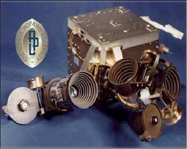
GRB (Gamma-Ray Burst Experiment)
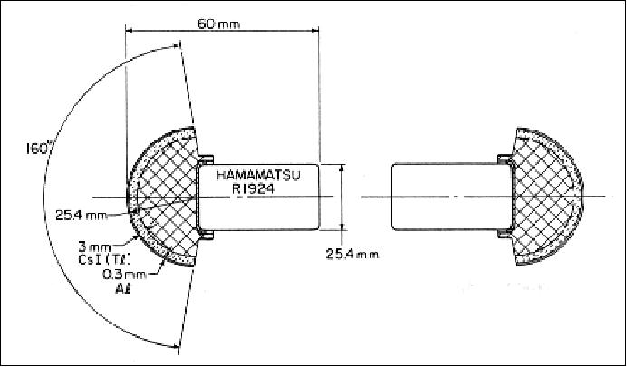
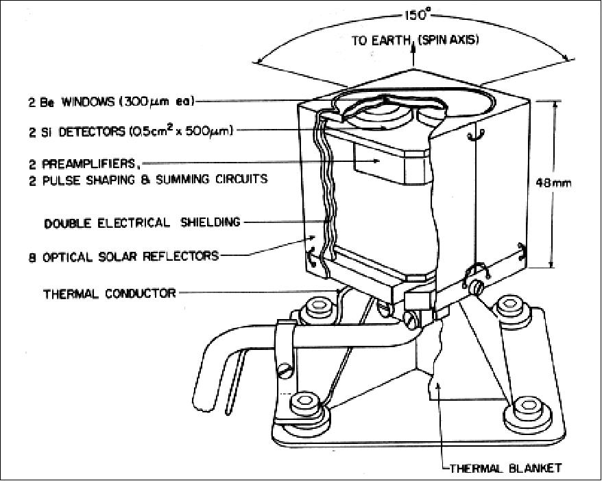
PI: K. C. Hurley, UCB (University of California, Berkeley). Objective: Measurement of the intensity and the spectral characteristics of X-ray and gamma-ray bursts of solar and cosmic origin. Localization of the sources of bursts of high-energy photons. 40)
The instrument consists of a gamma-ray sensor and a soft X-ray sensor mounted on the S/C radial boom, and a data processing unit inside the S/C. The gamma-ray sensor consists of two hemispherical Csl scintillation crystals coupled to PMT detectors; FOV =4 π (nearly unobstructed view); energy range = 15-150 keV. The soft X-ray sensor measures X-rays in the energy range 5-15 keV; it consists of two Si surface-barrier detectors and front-end electronics passively cooled to -50ºC. Mass=2.0 kg, power=2.6 W, data rate=40 bit/s.
HI-SCALE (Heliosphere Instrument for Spectra Composition and Anisotropy at Low Energies)
PI: L. J. Lanzerotti, AT&T Bell Labs/Lucent Technologies, Murray Hill, NJ. Objective: Measurement of interplanetary ions and electrons at the lowest energies covered by the suite of energetic-particle experiments. Ions at energies >50 keV and electrons above 30 keV are detected by five separate solid-state detector telescopes, oriented to give essentially complete pitch-angle coverage of the spinning S/C. Two of the telescopes contain magnets that prevent low-energy electrons from reaching the detectors, permitting clean ion measurements. Thin aperture foils that stop low-energy ions but allow electrons to pass freely are included in the 3rd and 4th telescopes. The 5th telescope performs ion-composition measurements (three detector elements). Mass=5.8 kg, power=4.0 W, data rate=160 bit/s. 41)
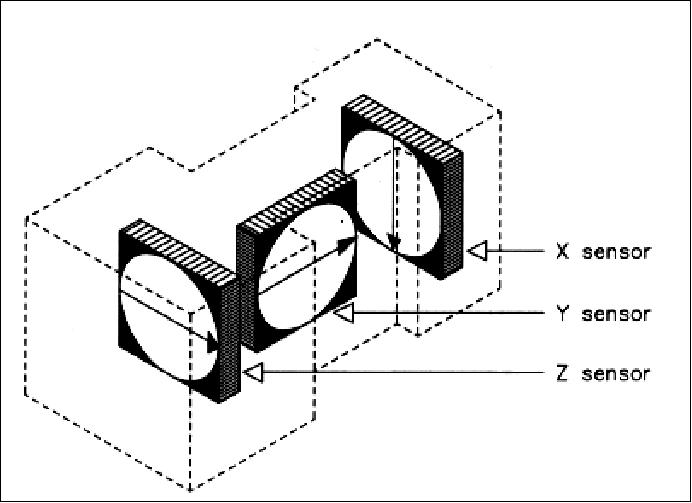
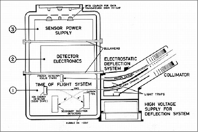
SWICS (Solar Wind Ion Composition Spectrometer)
PI: G. Gloeckler, University of Maryland; J. Geiss, University of Bern, Switzerland. Objective: Measurement of the chemical and ionic-charge composition of solar-wind ions, as well as their temperatures and mean speeds. Detection of all major solar-wind ions from H through Fe, at solar-wing speeds ranging from 145 km/s (protons) to 1352 km/s (Fe+8). 42)
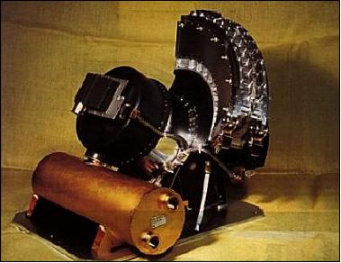
The instrument consists of an electrostatic analyzer (fan-shaped collimator enclosing the electrostatic deflection system), a time-of-flight telescope (contained in a drum-shaped high-voltage bubble), and solid-state proton/alpha detectors. Measurement of ion energy per charge, mass, and total energy, determination of the atomic mass (by combining the speed and total energy signals), and the ionization state of the particle (by combining the energy per charge and total energy values). Mass=5.6 kg, power=4.0 W, data rate=88 bit/s.
SWOOPS (Solar Wind Observations Over the Poles of the Sun)
PI: D. J. McComas, SWRI (Southwest Research Institute), San Antonio, TX. Objective: Observation of the solar-wind flow at middle-to-high solar latitudes for the construction of a representative model of the heliosphere. Measurement of the bulk flow parameters (density, speed and direction) of the solar wind in three dimensions at all heliocentric distances and heliographic latitudes reached by the S/C. 43)
The SWOOPS experiment comprises two separate instrument units, one for electrons and one for ions. These instruments, although different in size and detail, are based on the same basic principles. Both are electrostatic energy per charge (E/q) analyzers followed by sets of channel electron multiplier (CEM) sensors, which allow individual particles transmitted through the analyzers to be counted. In both cases, full complements of low and high voltage power supplies, memory, data processing capabilities, and spacecraft interfaces are provided as a part of the package such that each of the two instrument units is operated completely independently of the other. The CEMs are arranged so that particle velocity distributions can be resolved for all orientations of the S/C spin axis. Electrons with energies between 1-900 eV are detected; the measurement range for ions is 35 to 257 eV/Q. The ion instrument incorporates a stepper-motor-driven aperture wheel with seven apertures. Mass=6.7 kg, power=5.5 W, data rate=160 bit/s. 44) 45)
URAP (Unified Radio and Plasma-Wave Experiment)
PI: R. J. MacDowall, NASA/GSFC. Objective: Detection of distant radio wave emissions (via remote sensing) and detection of locally-generated plasma waves; tracking of solar radio noise bursts as they travel away from the sun for the study of the heliospheric magnetic field and solar wind flows. The antennas used by this experiment consist of a pair of wire booms (72 m tip-to-tip) lying in the S/C spin plane forming a dipole, and an axial boom (7.5 m long) which forms a monopole antenna along the S/C spin axis. Mass=7.4 kg (excluding antennas), power= 10 W, data rate=232 bit/s. 46) 47)
The URAP instrument was designed with the capability of performing direction finding on sources of radio waves. For the most accurate and complete determination of source directions, both the X and Z axis antennas are used to find the solution. The azimuthal angle of the source is determined by observing the modulation of the signal as the spacecraft spins. The URAP instrument takes a series of measurements during each spin. The high frequency part of URAP is used, it has 12 frequencies in the range 52 to 940 kHz range.
GWE (Gravitational Wave Experiment)
PI: B. Bertotti, University of Padua, Italy. Objective: Search for low-frequency wide-band gravitational waves thought to be emitted from various sources. If Ulysses is exposed to a burst of gravitational waves, then the S/C will experience a minute perturbation in its orbital velocity, which in turn produces a characteristic noise component in the Doppler-shifted radio signal received on the ground. 48) 49)
SCE (Solar Corona Experiment)
PI: M. K. Bird, University of Bonn, Germany. Two radio-science experiments are being carried out with the Ulysses S/C by making use of the S/C and ground communication equipment (SCE and GWE). SCE conducts coronal sounding using dual-frequency ranging and Doppler measurements during times of superior conjunction in order to determine the electron flux density and solar-wind velocity in the solar corona (also mapping of the electron content in the high-latitude heliosphere). 50)
Two radio science investigations, using the spacecraft and the ground communication equipment, were conducted during specific missions periods.
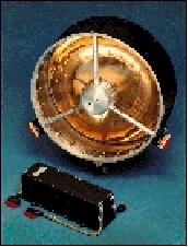
GPHS-RTG (General-Purpose Heat Source - Radioisotope Thermoelectric Generator)
The GPHS-RTG, the power source of Ulysses, is composed of two main elements: the general-purpose heat source (GPHS) assembly and the converter. The GPHS assembly consists of 18 modules, each containing four fueled clads that combined (using fresh fuel) produce about 245 W per module for a total of about 4410 W which the converter with its 572 SiGe (Silicon Germanium)) alloy thermoelectric elements converts into at least 285 We at beginning-of-mission (BOM). 51)
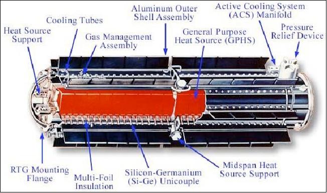
The GPHS-RTG has an overall diameter of 0.422 m and a length of 1.14 m with a mass of about 55.9 kg (including the 11 kg of Plutonium). For the originally planned May 1986 launch of Ulysses, the power requirement for the Ulysses mission called for at least 250 We with one GPHS-RTG at 4.7 years (41,200 h) after BOM, at a bus voltage of 28 V.
The RTG for Ulysses was provided by DOE (Department of Energy). The Oak Ridge National Laboratory developed and fabricated the material used to encapsulate the plutonium; Los Alamos National Laboratory purified, pelletized into a ceramic form and encapsulated the plutonium; and Idaho National Laboratory assembled and tested the RTG and safely delivered the flight-ready RTG to the Kennedy Space Center (KSC). 52)
References
1) R. G. Marsden, E. J. Smith, "News from the Sun's Poles - Courtesy of Ulysses," ESA Bulletin No 114, May 2003, pp. 60-67, URL: http://www.esa.int/esapub/bulletin/bullet114/chapter7_bul114.pdf
2) ESA Bulletin No. 63, August 1990, Special Issue on Ulysses
3) N. Angold, et al., "Ulysses Operations at Jupiter - Planning the Unknown," ESA Bulletin No. 72, November 1992, pp. 44-51
4) R. G. Marsden, K. P. Wenzel, "The Ulysses Jupiter Flyby - The Scientific Results," ESA Bulletin No. 72, November 1992, pp. 52-59
5) R. G. Marsden, "Ulysses Explores the South Pole of the Sun," ESA Bulletin No. 82, May 1995, pp. 48-55, URL: http://www.esa.int/esapub/bulletin/bullet82/mars82.htm
6) K. P. Wenzel, et al., "The Ulysses Mission," Astronomy and Astrophysics, Supplement Series, Vol. 92, January 1992, pp. 207-219
7) R. G. Marsden, E. J. Smith, "The Ulysses mission: An introduction," Special Session on the Ulysses mission of the XXIV International Cosmic-Ray Conference, Rome, Italy, August 28 - September 8, 1995
8) http://ulysses.jpl.nasa.gov/index.html
9) http://www.esa.int/esaSC/120395_index_0_m.html
10) http://sci.esa.int/science-e/www/area/index.cfm?fareaid=11
11) http://ulysses-ops.jpl.esa.int/ulsfct/spacecraft/scframe.html
12) http://ulysses.jpl.nasa.gov/science/jupiter_flyby_intro.html
13) R. G. Marsden, " Ulysses at Solar Maximum and Beyond," ESA Bulletin, No 103, Aug. 2000, pp. 41-47, URL: http://www.esa.int/esapub/bulletin/bullet103/marsden103.pdf
14) A. Mc Garry, N. Angold, "Ulysses 7 Years On - Operational Challenges and Lessons Learned," ESA Bulletin No. 92, November 1997, pp. 69-74, URL: http://www.esa.int/esapub/bulletin/bullet92/b92mcgar.htm
15) R. G. Marsden, K. P. Wenzel, "The Heliosphere in Perspective - Key Results from the Ulysses Mission at Solar Minimum," ESA Bulletin No. 92, November 1997, pp. 75-81, URL: http://www.esa.int/esapub/bulletin/bullet92/b92marsd.htm
16) http://sci.esa.int/science-e/www/object/index.cfm?fobjectid=41770
17) "Boost into the third dimension," Airbus DS, Feb. 8, 2017, URL: https://airbusdefenceandspace.com/newsroom/news-and-features/boost-into-the-third-dimension/
18) Harald Krüger, Peter Strub, Eberhard Grün, Veerle J. Sterken, "Sixteen years of Ulysses interstellar dust measurements in the Solar System. I. Mass distribution and gas-to-dust mass ratio," Astrophysical Journal, Volume 812, Issue 2, October 20, 2015, URL: http://iopscience.iop.org/article/10.1088/0004-637X/812/2/139/pdf
19) "Ulysses: 12 extra months of valuable science," ESA, June 30, 2009, URL: http://www.esa.int/SPECIALS/Operations/SEMWHF1P0WF_0.html
20) http://helio.esa.int/ulysses/
21) http://www.esa.int/esaSC/SEMPEQUG3HF_index_0_ov.html
22) "Joint ESA/NASA Ulysses mission to end," ESA, June 26, 2009, URL: http://www.esa.int/esaSC/SEMPL71P0WF_index_0.html
23) Programs in Progress," ESA Bulletin No 135, Aug. 2008, p. 54, URL: http://www.esa.int/esapub/bulletin/bulletin135/bul135_pip.pdf
24) http://www.esa.int/esaSC/SEMUHTN2UXE_index_0.html
25) "Ulysses' mission extended," Nov. 15, 2007, URL; http://www.esa.int/esaSC/SEM3KY53R8F_index_0.html
26) http://ulysses-ops.jpl.esa.int/ulsfct/milestones1.html
27) "Ulysses spacecraft data indicate Solar System shield lowering," ESA, Sept. 23, 2008, URL: http://www.esa.int/esaSC/SEMR9MQ4KKF_index_0.html
28) J. A. Simpson, J. D. Anglin, A. Balogh, M. Bercovitch, J. M. Bouman, E. E. Budzinski, J. R. Burrows, R. Carvell, J. J. Connell, R. Ducros, P. Ferrando, J. Firth, M. Garcia-Munoz, J. Henrion, R. J. Hynds, B. Iwers, R. Jacquet, H. Kunow, G. Lentz, R. G. Marsden, R. B. McKibben, R. Mueller-Mellin, D. E. Page, M. Perkins, A. Raviart, T. R. Sanderson, H. Sierks, L. Treguer, A. J. Tuzzolino, K.-P. Wenzel, G. Wibberenz, "The Ulysses cosmic ray and solar particle investigation," Astronomy and Astrophysics Supplement Series, Ulysses Instruments Special Issue, Vol. 92, No 2, January 1992., pp. 365-399, URL: http://ulysses.sr.unh.edu/WWW/Simpson/UlyDocs/CSPNWWWObj.html
29) http://ulysses.sr.unh.edu/WWW/Simpson/Ulysses.html
30) http://www.windows.ucar.edu/tour/link=/space_missions/cospininst.html
31) E. Grün, H. Fechtig, R. H. Giese, J. Kissel, D. Linkert, D. Maas, J. A. M. McDonnell, G. E. Morfill, G. Schwehm, H. A. Zook," "The Ulysses dust experiment," Astronomy and Astrophysics Supplement Series, Vol. 92, No 2, January 1992., pp. 411-423
32) E. Grün, M. Baguhl, N. Divine, H. Fechtig, D. P. Hamilton, M. S. Hanner, et. al., "Two years of Ulysses dust data," Planetary Space Science, Vol. 43, No 8, 1995, pp. 971-999, URL: http://www.astro.umd.edu/~hamilton/research/reprints/GruBagDiv95.pdf
33) E. Keppler, J. B. Blake, D. Hovestadt, A. Korth, J. Quenby, G. Umlauft, J. Woch, "The ULYSSES energetic particle composition experiment EPAC," Astronomy and Astrophysics Supplement Series, Ulysses Instruments Special Issue, Vol. 92, No 2, Jan. 1992, pp. 317-331
34) http://sci.esa.int/science-e/www/object/index.cfm?fobjectid=40406&fbodylongid-1933
35) http://www.bernd-leitenberger.de/ulysses.shtml
36) http://www.mps.mpg.de/en/projekte/ulysses/epac/
37) M. Witte, H. Rosenbauer, E. Keppler, H. Fahr, P. Hemmerich, H. Lauche, A. Loidl, R. Zwick, "The interstellar neutral-gas experiment on ULYSSES," Astronomy and Astrophysics Supplement Series, Ulysses Instruments Special Issue, Vol. 92, No 2, Jan. 1992, pp. 333-348
38) http://www.mps.mpg.de/en/projekte/ulysses/gas/
39) A. Balogh, T. J. Beek, R. J. Forsyth, P. C. Hedgecock, R. J. Marquedant, E. J. Smith, D. J. Southwood, B. T. Tsurutani," The magnetic field investigation on the Ulysses mission: Instrumentation and preliminary scientific results," Astronomy and Astrophysics Supplement Series, Vol. 92, January 1992, pp. 221-236
40) K. Hurley, M. Sommer, J.-L. Atteia, M. Boer, T. Cline, F. Cotin, J.-C. Henoux, S. Kane, P. Lowes, M. Niel, J. Van Rooijen, G. Vedrenne, Astronomy and Astrophysics Supplement Series, Ulysses Instruments Special Issue, Vol. 92, No. 2, pp. 401-410, Jan. 1992
41) http://sd-www.jhuapl.edu/Ulysses/hiscale.html
42) G. Gloeckler, J. Geiss, H. Balsiger, P. Bedini, J. C. Cain, J. Fisher, L. A. Fisk, A. B. Galvin, F. Gliem, D. C. Hamilton, J. V. Hollweg, F. M. Ipavich, R. Joos, S. Livi, R. Lundgren, U. Mall, J. F. McKenzie, K. W. Ogilvie, F. Ottens, W. Rieck, E. O. Tums, R. von Steiger, W. Weiss, B. Wilken, "The Solar Wind Ion Composition Experiment," Astronomy and Astrophysics Supplement Series, Vol. 92 No 2, January 1992, pp. 267-289
43) S. J. Bame, D. J. McComas, B. L. Barraclough, J. L. Phillips, K. J. Sofaly, J. C. Chavez, B. E. Goldstein, R. K. Sakurai, "The Ulysses Solar Wind Plasma Experiment," Astronomy and Astrophysics Supplement Series, Ulysses Instruments Special Issue, Vol. 92, No 2, pp. 237-265, 1992
44) http://www.windows.ucar.edu/tour/link=/space_missions/swoopsinst3.html
46) http://urap.gsfc.nasa.gov/instrument.html
47) R. G. Stone, J. L. Bougeret, J. Caldwell, P. Canu, Y. de Conchy, N. Cornilleau-Wehrlin, M. D. Desch, J. Fainberg, K. Goetz, M. L. Goldstein, C. C. Harvey, S. Hoang, R. Howard, M. L. Kaiser, P. J. Kellogg, B. Klein, R. Knoll, A. Lecacheux, D. Lengyel- Frey, R .J. MacDowall, R. Manning, C. A. Meetre, A. Meyer, N. Monge, S. Monson, G. Nicol, M. J. Reiner, J. L. Steinberg, E. Torres, C. de Villedary, F. Wouters, P. Zarka, "The unified radio and plasma wave investigation," Astronomy and Astrophysics Supplement Series, Vol. 92, No. 2, Jan. 1992, pp. 291-316
48) http://sci.esa.int/science-e/www/object/index.cfm?fobjectid=40406&fbodylongid-1940
49) B. Bertotti, R. Ambrosini, S. W. Asmar, J. P. Brenkle, G. Comoretto, G. Giampieri, L. Iess, A. Messeri, H. D. Wahlquist, "The gravitational wave experiment," Astronomy and Astrophysics Supplement Series, Ulysses Instruments Special Issue, Vol. 92, No. 2, pp. 431-440, Jan. 1992
50) M. K. Bird, S. W. Asmar, J. P. Brenkle, P. Edenhofer, M. Paetzold, H. Volland, "The coronal-sounding experiment," Astronomy and Astrophysics Supplement Series, Vol. 92 No. 2, January 1992., pp. 425-430
51) G. L. Bennett, J. J. Lombardo, R. J. Hemler, G. Silverman, C. W. Whitmore, A. Schock, R. W. Zocher, T. K. Keenan, J. C. Hagan, R. W. Englehart, "Mission of Daring: The General-Purpose Heat Source Radioisotope Thermoelectric Generator," 4th International Energy Conversion Engineering Conference and Exhibit (IECEC), June 26-29, 2006, San Diego, CA, USA, AIAA 2006-4096, URL: http://www.fas.org/nuke/space/gphs.pdf
52) "RTG — History and New Horizons," URL: http://www.osti.gov/accomplishments/rtg.html
The information compiled and edited in this article was provided by Herbert J. Kramer from his documentation of: "Observation of the Earth and Its Environment: Survey of Missions and Sensors" (Springer Verlag) as well as many other sources after the publication of the 4th edition in 2002. - Comments and corrections to this article are always welcome for further updates (eoportal@symbios.space).
Spacecraft Launch Mission Status Sensor Complement References Back to top