THEMIS (Time History of Events and Macroscale Interactions during Substorms)
EO
NASA
Operational (extended)
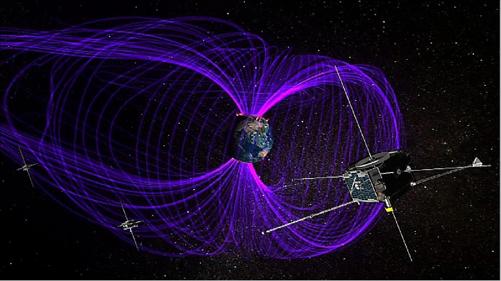
Launched in March 2007, THEMIS (Time History of Events and Macroscale Interactions during Substorms) is a NASA mission consisting of five nearly identical probes which study energy releases in Earth's magnetosphere, known as substorms. In 2010, the two outer probes were redirected into a Lunar orbit to form a new mission named ARTEMIS (Acceleration, Reconnection, Turbulence, and Electrodynamics of the Moon's Interaction with the Sun) and collect information about the space environment of the moon.
Quick facts
Overview
| Mission type | EO |
| Agency | NASA |
| Mission status | Operational (extended) |
| Launch date | 17 Feb 2007 |
| CEOS EO Handbook | See THEMIS (Time History of Events and Macroscale Interactions during Substorms) summary |
Summary
Mission Capabilities
All THEMIS/ARTEMIS probes carry the same suite of five sensors. This payload includes two magnetometers, an FGM (fluxgate magnetometer) to measure the 3D ambient magnetic field, and an SCM (search coil magnetometer) to measure the variation of magnetic flux. Each probe also hosts an ESA (electrostatic analyzer) to measure electrons and ions with a high temporal resolution, an SST (solid state telescope) to measure the super-thermal component of the ion and electron distributions, and an EFI (electric field instrument) to sense the electric field in Earth's magnetosphere.
Performance Specifications
The five THEMIS satellites were originally launched into 1.07 Re × 14.2 Re 13.4° orbits before using onboard mono-propellant propulsion systems to manoeuvre into their primary science constellation configuration. The orbital period of ARTEMIS probes ranges from one to four days, with inclinations from 4.5° to 9.0°. In March 2011, the two outer THEMIS probes transitioned into an elliptical Lunar orbit to form the new ARTEMIS mission.
The THEMIS constellation achieves an apogee alignment of the HEOs (highly elliptical orbits) at local midnight over North America in the winter to provide the required spatial and temporal sampling of the local plasma, electric field, and magnetic field.
Space and Hardware Components
All THEMIS probes use identical 5-spin-stabilised buses, designed and built by Swales Aerospace, Beltsville, Maryland. Each bus is composed of a magnetically clean and externally conductive graphite structure, with a square-shaped body and a total mass of 128 kg.
Spacecraft attitude is measured using a Miniature Spinning Sun Sensor (MSSS), two single-axis Inertial Reference Units (IRU), and a Flux Gate Magnetometer (FGM). To control spacecraft attitude each bus hosts a Reaction Control Subsystem (RCS) - a hydrazine blowdown system pressurised with helium. Power is provided via a Direct Energy Transfer (DET) topology, with the battery and solar array connected directly to the bus. Both uplink and downlink spacecraft communications are sent via S-band RF (radio frequency).
THEMIS (Time History of Events and Macroscale Interactions during Substorms) / ARTEMIS
Spacecraft Launch Mission Status Sensor Complement Ground Segment ARTEMIS References
THEMIS is a mission within NASA's MIDEX (Medium Explorer) program, approved in May 2004. The goal of THEMIS is to fly five small spacecraft through explosive geomagnetic disturbances to solve the mystery of what triggers the colorful eruptions of the Northern and Southern lights. These violent ”substorms” reflect major reconfigurations of near-Earth space and have significant implications for space weather, affecting satellites and terrestrial communications.
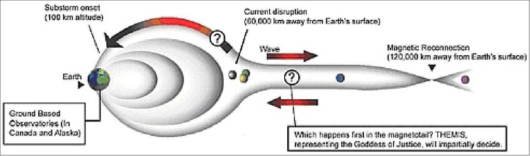
The overall objective is to study fundamental questions regarding the magnetospheric substorm instability, a dominant mechanism of transport and explosive release of solar wind energy within Geospace. THEMIS will elucidate which magnetotail process is responsible for substorm onset at the region where substorm auroras map (~10 RE): i) a local disruption of the plasma sheet current or ii) that current's interaction with the rapid influx of plasma emanating from lobe flux annihilation at ~25 RE. Correlative observations from long-baseline (2-25 RE) probe conjunctions, will delineate the causal relationship and macroscale interaction between the substorm components.
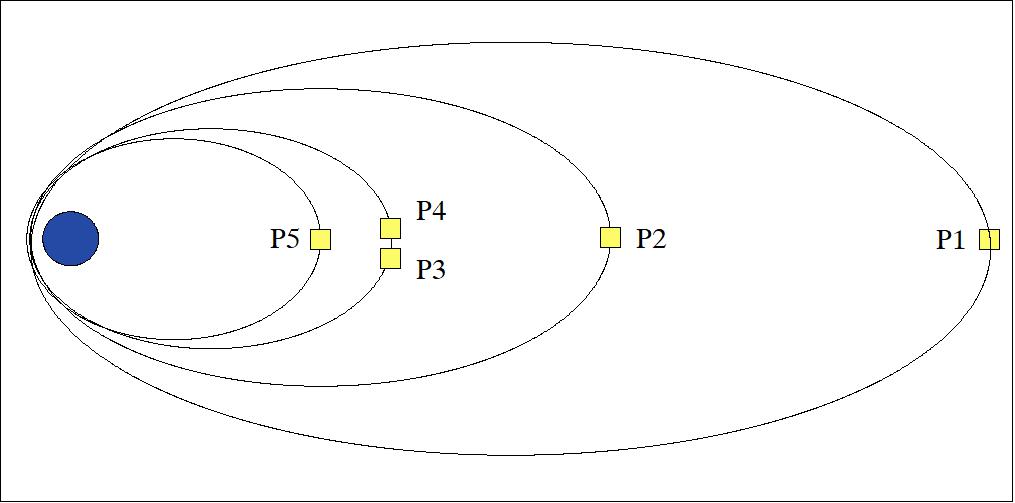
The five identical probes (P1, P2, P3, P4, P5) of THEMIS measure particles and fields on orbits which optimize tail-aligned conjunctions over North America. Ground observatories time auroral breakup onset. Three inner probes at ~10 RE monitor current disruption onset, while two outer probes, at 20 and 30 RE respectively, remotely monitor plasma acceleration due to lobe flux dissipation. In addition to addressing its primary objective, THEMIS answers critical questions in radiation belt physics and solar wind - magnetosphere energy coupling. THEMIS's probes use flight-proven instruments and subsystems, yet demonstrate spacecraft design strategies ideal for Constellation class missions. THEMIS is complementary to NASA's MMS (Magnetosphere Multistage) program and a science and a technology pathfinder for future STP (Solar Terrestrial Probe) missions. 1) 2) 3)
In July 2009, the THEMIS mission split into two missions:
- The first, THEMIS-Low, consisting of the three inner probes (P3, P4, P5), will continue to study the Earth's space environment.
- The two outer probes, P1 and P2, will explore the space environment of the moon. This new mission was renamed to ARTEMIS (Acceleration Reconnection Turbulence, and Electrodynamics of Moon Interaction with the Sun). The ARTEMIS mission is a collaborative effort between NASA/GSFC, UCB (University of California at Berkeley), and NASA/JPL (Jet Propulsion Laboratory).
The THEMIS science objectives are:
• Onset and evolution of the macroscale substorm instability, a fundamental mode of mass, and energy transport throughout Geospace
• Production of storm-time MeV electrons
• Control of the solar wind-magnetosphere coupling by the bow shock, magnetosheath, and magnetopause.
THEMIS is essential for understanding Earth's space environment and a prerequisite to understanding space weather.
THEMIS is a NASA PI mission, lead by Vassilis Angelopoulos at SSL (Space Sciences Laboratory) of the University of California, Berkeley (UCB). In turn, UCB awarded Swales Aerospace the prime contract for design, development and integration of the THEMIS satellite constellation and satellite dispensers.
Note: In the spring of 2007, Swales Aerospace of Beltsville, MD was purchased by Alliant Techsystems Inc. (ATK) with corporate headquarters in Edina, Minnesota.
In Greek mythology, Themis is the goddess of justice, wisdom and good counsel, and the guardian of oaths.
Spacecraft
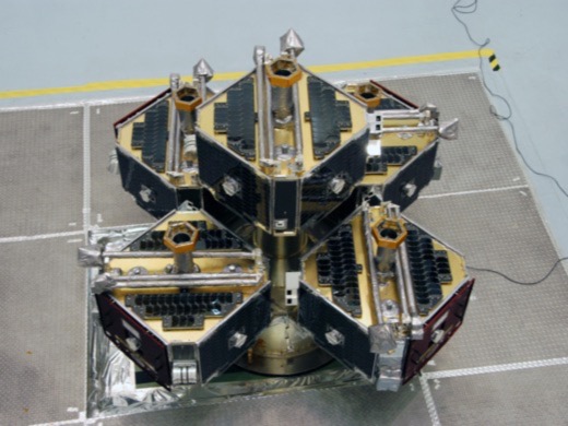
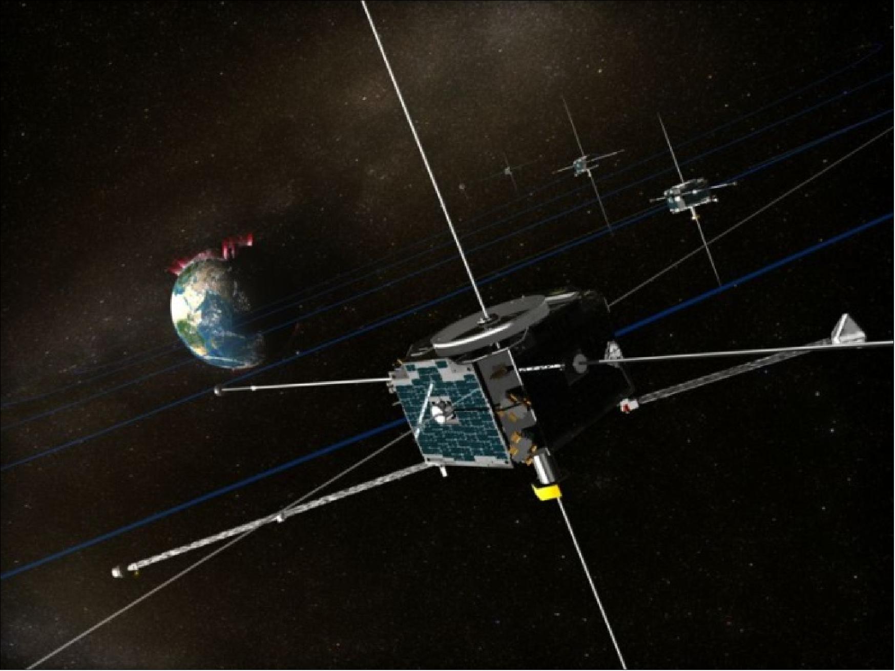
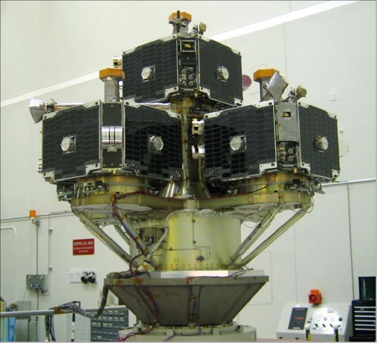
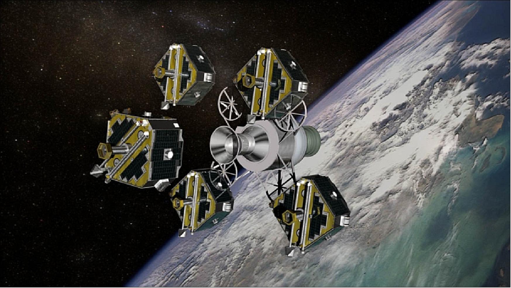
THEMIS consists of a constellation of five spin-stabilized microsatellites (called Probes), each a highly integrated “sciencecraft.” The spacecraft buses, including the separation system and carrier, are designed and built by Swales Aerospace, Beltsville, MD. The science requirements call for a spacecraft that is magnetically clean and externally conductive. 4) 5) 6)
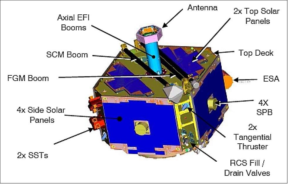
The spacecraft design is based on a single bus architecture with selected redundancy and some graceful degradation. The bus is composed of a graphite structure with an approximately square-shaped body with eight sides, a top deck, a bottom deck and an axial tube (referred to as mast). The primary structure consists of four side panels with face-mounted solar arrays. Each spacecraft has a total mass of 128 kg. The S/C size is: 84 cm x 84 cm x 51 cm (height) excluding the mast holding the RF antenna above the bus and the instruments in the stowed position. 7) 8)
An average power of 39 W (EOL) is provided for the worst case 24 hour orbit with a 3 hour eclipse, and 58 W BOL (Beginning of Life) with no eclipse.
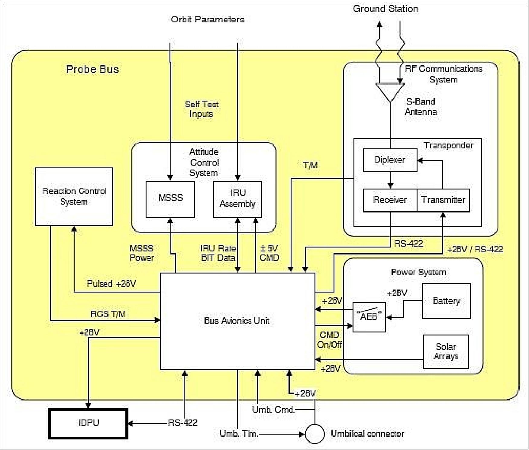
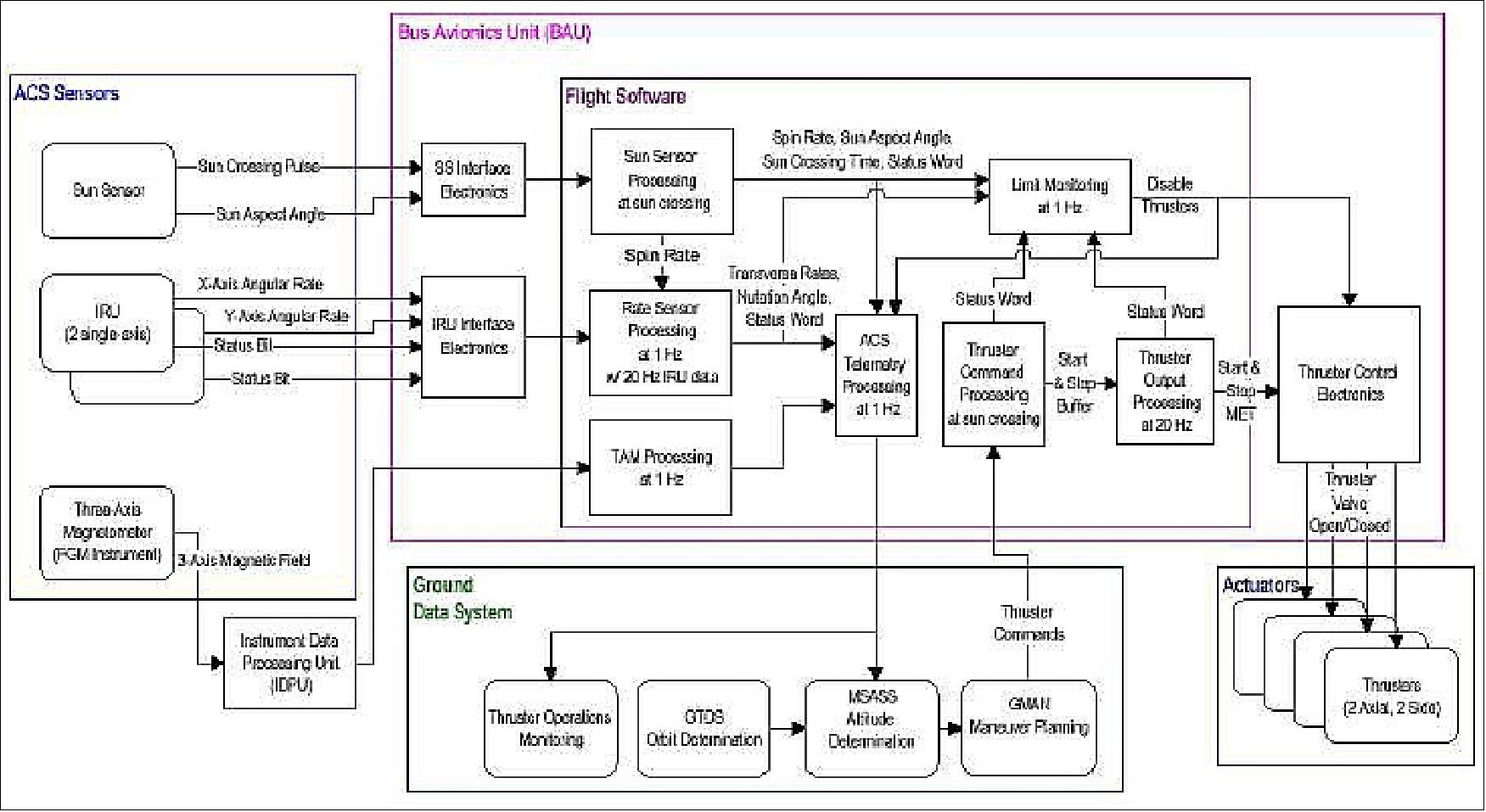
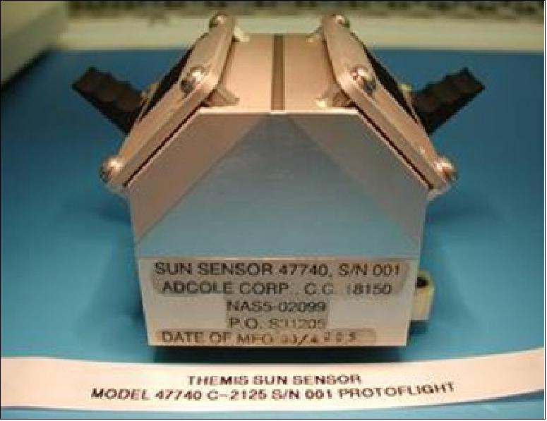
The spacecraft attitude is measured by a digital spinning sun sensor, referred to as MSSS (Miniature Spinning Sun Sensor), two single axis IRUs (Inertial Reference Unit), and the science instrument FGM (Flux Gate Magnetometer). The GN&C (Guidance Navigation & Control) subsystem includes the ACS (Attitude Control Subsystem) and the RCS (Reaction Control Subsystem). The ACS utilizes a thruster interface driven by ground-processed estimation and command algorithms with on-board limit and time-out protection. Attitude data collected from the MSSS and the FGM are sampled at 10 Hz and telemetered to the ground for standard, 3-axis, post-processing estimation. Ground generated thruster command sequences are tested in a high-fidelity probe simulator prior to any upload. Also, two single-axis gyros, transverse to the spin plane, provide short-term attitude verification (prior to orbit maneuvers). The on-board protection logic monitors real-time sun aspect angle and spin period, comparing them to a ground commanded reference uploaded for each maneuver. If thresholds are exceeded, the maneuver is terminated. Actuation is provided by the RCS consisting of the four thruster complement and the two fuel tanks (Inconel), operated in a blow-down fashion. The tanks feed a four thruster complement (5 N for each thruster, two axial, two radial for spin and pointing control).
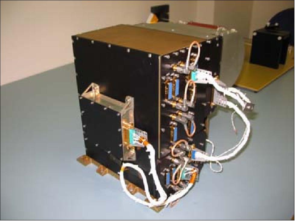
The S/C avionics are stowed into a single box called BAU (Bus Avionics Unit). BAU features 3 modules: a single board computer module (identical to the IDPU processor card), a single board communication module (of SMEX heritage), and a 3-board power control module. BAU has a size of 23 cm x 15 cm x 13 cm and a mass of 2.8 kg. 9)
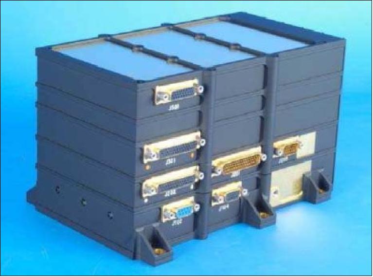
The CDHS (Command and Data Handling Subsystem) provides real-time and stored command capability for the bus subsystems and instruments, collects, formats, and transmits to the ground data from the bus subsystems and instruments, provides engineering data storage, distributes time to the IDPU (Instrument Data Processing Unit), and implements autonomous fault protection features to ensure the health and safety of the probe. The CDHS functions are implemented in flight software and hardware that reside in the BAU.
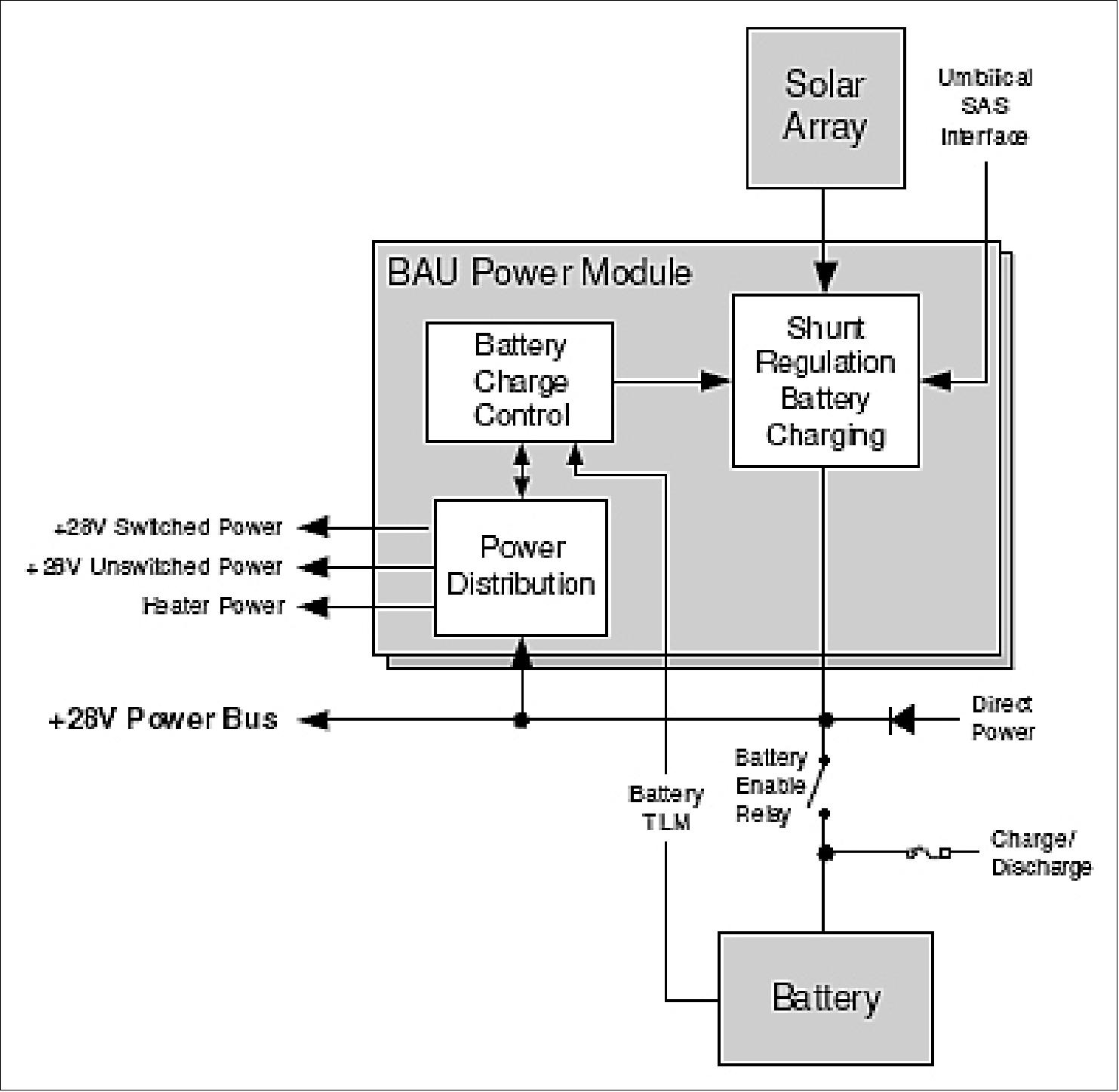
The power subsystem uses a DET (Direct Energy Transfer) topology with the battery and solar array (triple-junction GaAs cells) connected directly to the power bus. The solar array consists of eight panels, four on each side, and two on each deck. The power available is 41.7 W. Eclipse and peak transient loads (i.e., transmitter operation) are balanced with an 11.8 Ahr, 28 V Li-ion battery of ABSL. Thermal management using heaters and thermistors keeps the battery temperature in the range of -5º to +25º C. The power subsystem is contained in AEB (Auxiliary Electronics Box). The solar arrays feature a conductive glass cover and a complex external grounding scheme to minimize surface charging.
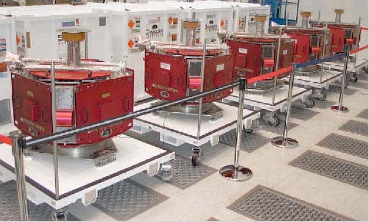
To obtain the required orbits, the five Probes will be deployed in nearly simultaneously separations from the spinning Probe Carrier (Figure 12), which is hard mounted to the Delta II 3rd stage. This unique deployment demands a custom-built separation system. Once deployed each Probe requires approximately 900 m/s of ΔV to reach its required science orbit (including inclination change) and perform its mission. The ΔV requirement creates the need for each Probe to carry 49 kg of hydrazine.
Note: The mass of a Probe bus was not dictated by the launch vehicle lift-off capacity since there was ample mass margin for the Probe Carrier Assembly (five probes and probe carrier) on the Delta II. Rather, the mass requirements were driven by the individual ΔV requirements (> 920 m/s) for the largest apogee orbit (Ref. 67).
The mission reliability scheme relies on the availability of only four out of five spacecraft for one winter season to meet the minimum science requirements. The constellation of five spin-stabilized satellites has a (nominal) baseline life of two years - with a possible one-year extension.
Nr of spacecraft in constellation | 5 |
Mass | - Spacecraft bus dry mass: 51 kg |
Power | - Spacecraft bus power: 11 W |
RF communications | - S band |
ACS | - Spin rate (science): 16 ±2 rpm |
Propulsion | - Monopropellant hydrazine system |
Radiation Environment | Total dose: 66 krad (2 years, 5 mm Al shielding, RDM of 2) |
Nominal mission design life | 2 years |
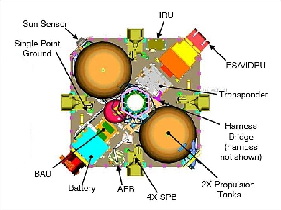
Propulsion subsystem: The RCS (Reaction Control Subsystem) is a hydrazine blowdown system pressurized with helium. The RCS consists of two spherical propellant tanks, a single use pyro-actuated re-pressurization tank, and four 4.5 N thrusters.
Two of the thrusters, A1 and A2, point parallel to the spacecraft’s spin-axis. When these two thrusters are fired in a continuous mode they provide a ΔV in the +Z spin-axis direction. These events are referred to as axial maneuvers. Attitude precession maneuvers are performed by firing either A1 or A2 in a sun-synchronous pulsed-mode.
The other two thrusters, T1 and T2, are mounted in a radial direction. When T1 and T2 are fired simultaneously in a sun-synchronous pulsed-mode these thrusters provide a ΔV in a radial direction, perpendicular to the spacecraft’s spin-axis. Firing either T1 or T2 alone, with thrust pulses phased 180º from each other provides control over the spacecraft’s spin rate while minimizing torque on the EFI wire booms.
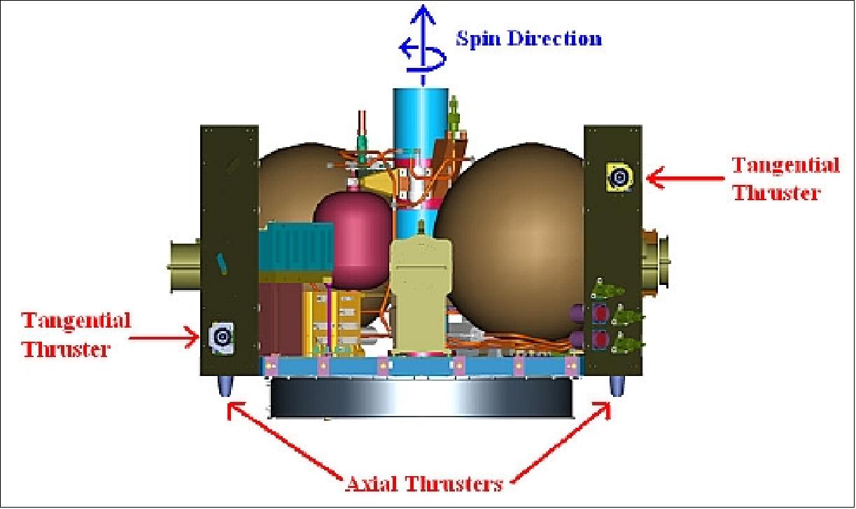
By combining the axial and radial maneuvers into a series of burns executed in short succession the spacecraft can thrust in any direction in the southern ecliptic hemisphere without performing an attitude precession to point the thrusters in a specific direction. However, there is a small vectorization ΔV penalty for performing maneuvers in this manner, but the ΔV cost incurred by performing an attitude precession is prohibitively higher due to the spacecraft’s large angular momentum.
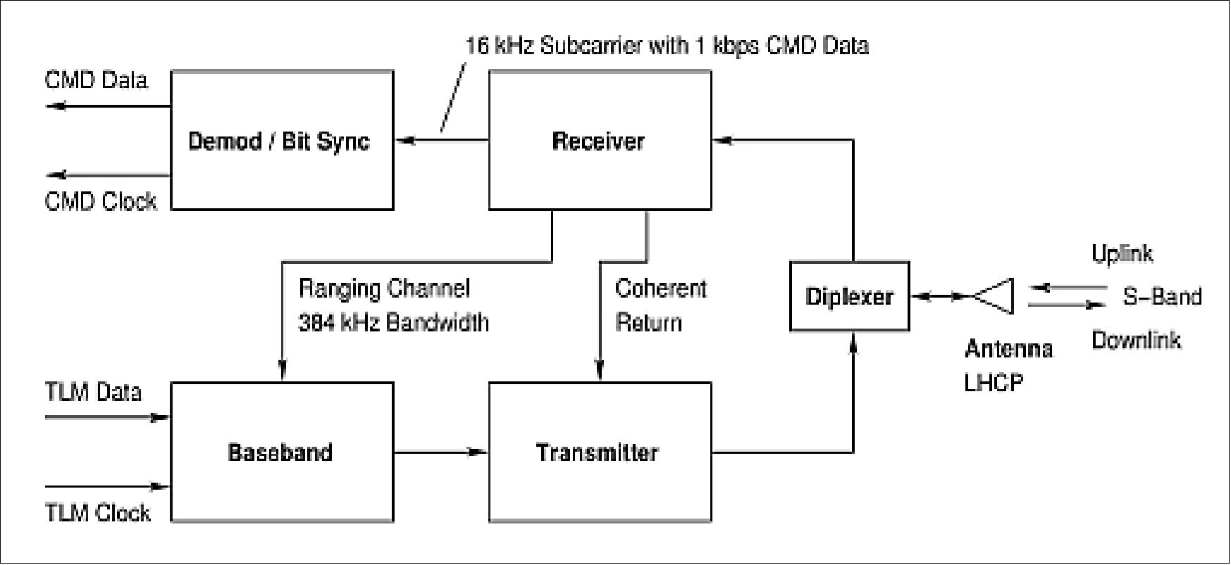
RF communications: An S-band system is being used based on a stacked patch antenna with a toroidal pattern that has a maximum gain normal to the spin axis of the bus. This configuration provides a continuous view of the Earth at nominal attitudes and insures an Earth view for the greatest part of the orbit at any attitude. - The antenna is fed by a 5 W STDN (Standard Tracking and Data Network) compatible transponder (with flight heritage) that features ranging and TDRSS compatibility including LEO support of a fixed 1 kbit/s uplink (operated in PCM/PSK/PM mode with a 16-kHz subcarrier at a modulation index of 1.0 rad). The downlink has 10 selectable rates from 1.024 to 1048.576 kbit/s. The communication protocol standard CCSDS is being used along with Reed-Salomon encoding. The telemetry channel can also be configured for direct carrier (BPSK) modulation with all 10 data rates.
All THEMIS probes are equipped with model CXS-610 transponders manufactured by L3 Communications Telemetry-West. All transponders operate on the same S-band frequencies. The transponder can be operated in PCM/PSK/PM mode with the lowest six data rates up to 65.536 kbit/s, utilizing a 1024 kHz subcarrier.
Frequency (S-band) | Downlink: 2282.5 MHz; uplink: 2101.8 MHz |
Polarization | LHCP (Left-Hand Circular Polarized) |
Modulation | Downlink: BPSK (4 highest data rates), PCM/PSK/PM (6 lowest data rates) |
Encoding | Downlink: Reed-Solomon + rate-1/2 convolution |
Compression Scheme (VC3 only) | Differencing and truncation or Huffman (TBR) |
Data rates | 1.024, 4.096, 8.192, 16.384, 32.768, 65.536, 131.072, 262.144, 524.288, 1048.576 kbit/s |
Virtual channels | 0-3, 6 |
Data volume per orbit per probe | 480 - 640 Mbit |
Launch
A common launch of all THEMIS spacecraft took place on Feb. 17, 2007 on a Delta-2-7925-10 vehicle. The launch site was CCAS (Cape Canaveral Air Station), FLA.
Orbit: HEO (Highly Elliptical Orbit) of constellation
• Probe 1: Orbital period of 4 days, perigee 1.500 RE, apogee 31.645 RE, inclination 7.0º
• Probe 2: Orbital period of 2 days, perigee 1.168 RE, apogee 19.770 RE, inclination 7.0º
• Probe 3: Orbital period of 1 day, perigee 1.118 RE, apogee 12.127 RE, inclination 9.0º
• Probe 4: Orbital period of 1 day, perigee 1.118 RE, apogee 12.127 RE, inclination 9.0º
• Probe 5, Orbital period of 0.8 days, perigee 1.350 RE, apogee 10.044 RE, inclination 4.5º
The five satellites use their onboard mono-propellant propulsion systems to maintain the primary science constellation configuration with orbital periods ranging from 1 to 4 days. The constellation alignment is carefully designed to achieve an apogee alignment of the HEOs at local midnight over North America in the winter. The orbits are designed to provide the required spatial and temporal sampling of the local plasma, electric field, and magnetic field. 12) 13)
Mission Status
Status of THEMIS / ARTEMIS (Acceleration Reconnection Turbulence, and Electrodynamics of Moon Interaction with the Sun) mission
• October 6, 2021: Earth sails the solar system in a ship of its own making: the magnetosphere, the magnetic field that envelops and protects our planet. The celestial sea we find ourselves in is filled with charged particles flowing from the Sun, known as the solar wind. Just as ocean waves follow the wind, scientists expected that waves traveling along the magnetosphere should ripple in the direction of the solar wind. But a new study reveals some waves do just the opposite. 14)
- Studying these magnetospheric waves, which transport energy, helps scientists understand the complicated ways that solar activity plays out in the space around Earth. Changing conditions in space driven by the Sun are known as space weather. That weather can impact our technology from communications satellites in orbit to power lines on the ground. “Understanding the boundaries of any system is a key problem,” said Martin Archer, a space physicist at Imperial College London who led the new study, published today in Nature Communications. “That’s how stuff gets in: energy, momentum, matter.” 15)
- Archer focuses on surface waves, meaning waves that require a boundary — in this case, the edge of the magnetosphere — to travel along. Previously, he and his colleagues established this boundary vibrates like a drum. When a strong burst of solar wind beats against the magnetosphere, waves race towards Earth’s magnetic poles and get reflected back.
- The latest work considers the waves that form across the entire surface of the magnetosphere, using a combination of models and observations from NASA’s THEMIS mission, Time History of Events and Macroscale Interactions during Substorms.
- The researchers found when solar wind pulses strike, the waves that form not only race back and forth between Earth’s magnetic poles and the front of the magnetosphere, but also travel against the solar wind. Archer likened these two kinds of movement to crossing a river: A boat can go from one riverbank to the other (traveling towards the poles) and upstream (against the solar wind). At the front of the magnetosphere, these waves appear to stand still.
- The THEMIS satellites’ observations from within the magnetosphere first hinted some waves might be traveling against the solar wind. The researchers used models to illustrate how the energy of the wind coming from the Sun and that of the waves going against it could cancel each other out. It’s similar to what happens if you try walking up a downwards escalator. “It’s going to look like you’re not moving at all, even though you’re putting in loads of effort,” Archer said.
- These standing waves can persist longer than those that travel with the solar wind. That means they’re around longer to accelerate particles in near-Earth space, leading to potential impacts in the radiation belts, aurora, or ionosphere. Archer expects standing waves may occur elsewhere in the universe, from the magnetospheres of other planets to the peripheries of black holes. Studying the waves close to home can help scientists understand such distant boundaries.
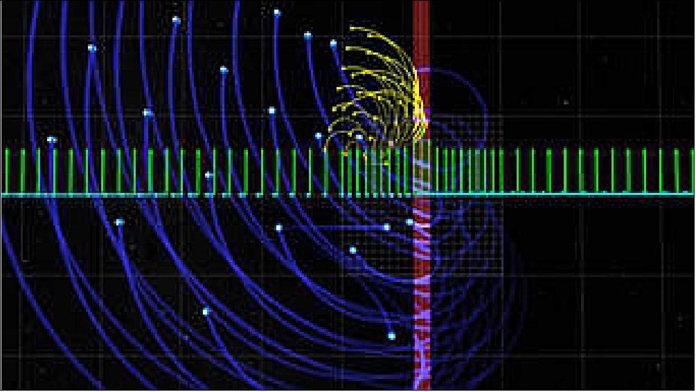
- By translating the wave models and data into the audible range, we can listen to the sound of these curious waves.
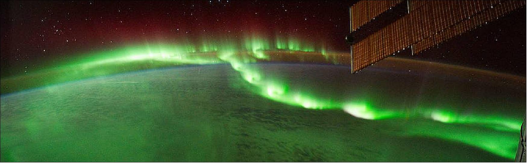
• August 14, 2020: A special type of aurora, draped east-west across the night sky like a glowing pearl necklace, is helping scientists better understand the science of auroras and their powerful drivers out in space. Known as auroral beads, these lights often show up just before large auroral displays, which are caused by electrical storms in space called substorms. Previously, scientists weren’t sure if auroral beads are somehow connected to other auroral displays as a phenomenon in space that precedes substorms, or if they are caused by disturbances closer to Earth’s atmosphere. 16)
- But powerful new computer models combined with observations from NASA’s Time History of Events and Macroscale Interactions during Substorms – THEMIS – mission have provided the first strong evidence of the events in space that lead to the appearance of these beads, and demonstrated the important role they play in our near space environment.
- “Now we know for certain that the formation of these beads is part of a process that precedes the triggering of a substorm in space,” said Vassilis Angelopoulos, principal investigator of THEMIS at the University of California, Los Angeles. “This is an important new piece of the puzzle.”
- By providing a broader picture than can be seen with the three THEMIS spacecraft or ground observations alone, the new models have shown that auroral beads are caused by turbulence in the plasma – a fourth state of matter, made up of gaseous and highly conductive charged particles – surrounding Earth. The results, recently published in the journals Geophysical Research Letters and Journal of Geophysical Research: Space Physics, will ultimately help scientists better understand the full range of swirling structures seen in the auroras. 17) 18)
- “THEMIS observations have now revealed turbulences in space that cause flows seen lighting up the sky as of single pearls in the glowing auroral necklace," said Evgeny Panov, lead author on one of the new papers and THEMIS scientist at the Space Research Institute of the Austrian Academy of Sciences. “These turbulences in space are initially caused by lighter and more agile electrons, moving with the weight of particles 2000 times heavier, and which theoretically may develop to full-scale auroral substorms.”
Mysteries of Auroral Beads Formation
- Auroras are created when charged particles from the Sun are trapped in Earth’s magnetic environment – the magnetosphere – and are funneled into Earth’s upper atmosphere, where collisions cause hydrogen, oxygen, and nitrogen atoms and molecules to glow. By modelling the near-Earth environment on scales from tens of miles to 1.2 million miles, the THEMIS scientists were able to show the details of how auroral beads form.
- As streaming clouds of plasma belched by the Sun pass Earth, their interaction with the Earth’s magnetic field creates buoyant bubbles of plasma behind Earth. Like a lava lamp, imbalances in the buoyancy between the bubbles and heavier plasma in the magnetosphere creates fingers of plasma 2,500 miles wide that stretch down towards Earth. Signatures of these fingers create the distinct bead-shaped structure in the aurora.
- “There's been a realization that, all summed up, these relatively little transient events that happen around the magnetosphere are somehow important,” said David Sibeck, THEMIS project scientist at NASA’s Goddard Space Flight Center in Greenbelt, Maryland. “We have only recently gotten to the point where computing power is good enough to capture the basic physics in these systems.”
- Now that scientists understand the auroral beads precede substorms, they want to figure out how, why and when the beads might trigger full-blown substorm. At least in theory, the fingers may tangle magnetic field lines and cause an explosive event known as magnetic reconnection, which is well known to create full-scale substorms and auroras that fill the nightside sky.
New Models Open New Doors
- Since its launch in 2007, THEMIS has been taking detailed measurements as it passes through the magnetosphere in order to understand the causes of the substorms that lead to auroras. In its prime mission, THEMIS was able to show that magnetic reconnection is a primary driver of substorms. The new results highlight the importance of structures and phenomenon on smaller scales – those hundreds and thousands of miles across as compared to ones spanning millions of miles.
- “In order to understand these features in the aurora, you really need to resolve both global and smaller, local scales. That's why it was so challenging up to now,” said Slava Merkin, co-author on one of the new papers and scientist at NASA’s Center for Geospace Storms headquartered at Johns Hopkins University Applied Physics Laboratory in Laurel, Maryland. “It requires very sophisticated algorithms and very big supercomputers.”
- The new computer simulations almost perfectly match THEMIS and ground observations. After the initial success of the new computer models, THEMIS scientists are eager to apply them to other unexplained auroral phenomena. Particularly in explaining small-scale structures, computer models are essential as they can help interpret what happens in between the spaces where the three THEMIS spacecraft pass.
- “There’s lots of very dynamic, very small-scale structures that people see in the auroras which are hard to connect to the larger picture in space since they happen very quickly and on very small scales,” said Kareem Sorathia, lead author on one of the new papers and scientist at NASA’s Center for Geospace Storms headquartered at Johns Hopkins Applied Physics Laboratory. “Now that we can use global models to characterize and investigate them, that opens up a lot of new doors.”
• As of 17 February 2019, the THEMIS mission is 12 years on orbit.
• February 12, 2019: Space isn’t silent. In fact, an entire orchestra of instruments fills our near-Earth environment with eerie sounds. Scientists have long known about space phenomena involving electromagnetic waves travelling around Earth that resonate like string instruments and whistle like wind instruments. Now, new research published in Nature Communications has added a percussive member to the cosmic ensemble: a giant drum, triggered by plasma jets striking the boundary of the protective magnetic bubble surrounding our planet. 19)
- This magnetic bubble, known as the magnetosphere, is encased by a boundary region known as the magnetopause, our first barrier to high-energy particles coming from the Sun. At the magnetopause, the majority of solar particles are deflected around Earth, but under certain conditions some sneak through. Understanding the mechanics of the magnetopause is key to helping keep our satellites, telecommunications and astronauts safe from the potentially harmful radiation these particles bring.
- Using data from NASA’s THEMIS (Time History of Events and Macroscale Interactions during Substorms) mission, the scientists discovered that when the magnetopause is struck by a jet of plasma from the Sun, it vibrates like a drum, with waves echoing back and forth along its surface, much like they do on top of a drumhead. The new discovery comes several decades after such behavior was first theorized.
- “Given the lack of evidence over the 45 years since they were proposed, there had been speculation that these drum-like vibrations might not occur at all,” said Martin Archer, space physicist at Queen Mary University of London and lead author of the new paper. “Now we see that waves on the magnetopause’s surface reflect between two points near the magnetic poles — acting very much like a drum." 20)
- Inside the magnetosphere, scientists have long been listening in on space sounds created by various electromagnetic waves. This veritable orchestra of waves can be heard as sound when processed correctly, and they even exhibit similar behaviors to certain musical instruments. So-called magnetosonic waves pulse through plasma in the same way sound bounces through wind instruments. Another type of wave, known as an Alfvén wave, resonates along magnetic field lines, just like string instruments’ vibrating strings. While both of these types of waves can travel anywhere in space, the newly discovered waves are a type of surface waves — waves that require some sort of boundary to travel along.
- In this case the magnetopause acted as the boundary. When a plasma jet — the drumstick — strikes the magnetopause, surface waves form a standing wave pattern — where the ends appear to be standing still while other points vibrate back and forth — just like a drumhead. The fixed points in the wave, which are the rim or edge of the drum, are near Earth’s magnetic poles; the waves vibrate the surface of the magnetopause in between. While the wave itself remains on the surface, the vibrations ultimately work their way down into the magnetosphere and trigger other types of waves.
- “The waves likely penetrate far into the inner magnetosphere causing ultra-low frequency waves, which affect things like radiation belts, the aurora, and even the ionosphere,” Archer said.
- The new study used data from the THEMIS mission, which initially used five identical probes to determine what physical process in near-Earth space initiates the auroras.
- "The authors make great use of observations from a time early in the mission when the spacecraft followed each other along their mutual orbit like pearls on a string,” said David Sibeck, THEMIS project scientist at NASA’s Goddard Space Flight Center in Greenbelt, Maryland. “In this fortunate case, the THEMIS spacecraft were in just the right place to see the drumstick and hear the drum."
- The scientists plan to look through archival THEMIS data for more of these events around Earth and determine how often the magnetopause may be booming like a drum. This research may also help provide insights into how to look for this phenomenon at other planets with magnetospheres, like Jupiter and Saturn, and what effect they may have in those systems.
• February 20, 2018: Sometimes on a dark night near the poles, the sky pulses a diffuse glow of green, purple and red. Unlike the long, shimmering veils of typical auroral displays, these pulsating auroras are much dimmer and less common. While scientists have long known auroras to be associated with solar activity, the precise mechanism of pulsating auroras was unknown. Now, new research, using data from NASA’s THEMIS (Time History of Events and Macroscale Interactions during Substorms) mission and Japan’s ERG (Exploration of energization and Radiation in Geospace), also known as Arase satellite, has finally captured the missing link thought responsible for these auroras. The answer lies in chirping waves that rhythmically pulse the particles that create the auroras. 21)
- Earth’s magnetic bubble — the magnetosphere — protects the planet from high-energy radiation coming from the Sun and interstellar space, but during particularly strong solar events, particles can slip through. Once inside, the particles and the energy they carry are stored on the nightside of the magnetosphere, until an event, known as a substorm, releases the energy. The electrons are then sent speeding down into Earth’s upper atmosphere where they collide with the other particles and produce the characteristic glow.
- Pulsating auroras, however, have a slightly different cause. The magnetosphere is home to a type of plasma wave known as whistler mode chorus. These waves have characteristic rising tones — reminiscent of the sounds of chirping birds — and are able to efficiently disturb the electrons. When these waves make their appearance within the magnetosphere, some of the electrons scattered by the wave careen down into Earth’s atmosphere, causing the pulsating auroras.
- While scientists have long believed this mechanism to be responsible for pulsating auroras, they had no definitive proof until now. The multipoint observations from the ERG satellite and ground-based all-sky cameras from the THEMIS mission allowed scientists to pinpoint the cause and effect, seeing the event from start to end. The results were published in the journal Nature. 22)
- Research done with NASA’s ground-based camera and Japan’s spacecraft in the near-Earth laboratory has applications further afield. Chorus waves have been observed around other planets in the solar system, including Jupiter and Saturn. Likely, the processes observed around Earth can help explain auroral features on these gas giants as well as on planets around other stars. The results also help scientists better understand how plasma waves can influence electrons — something that occurs in processes across the universe.
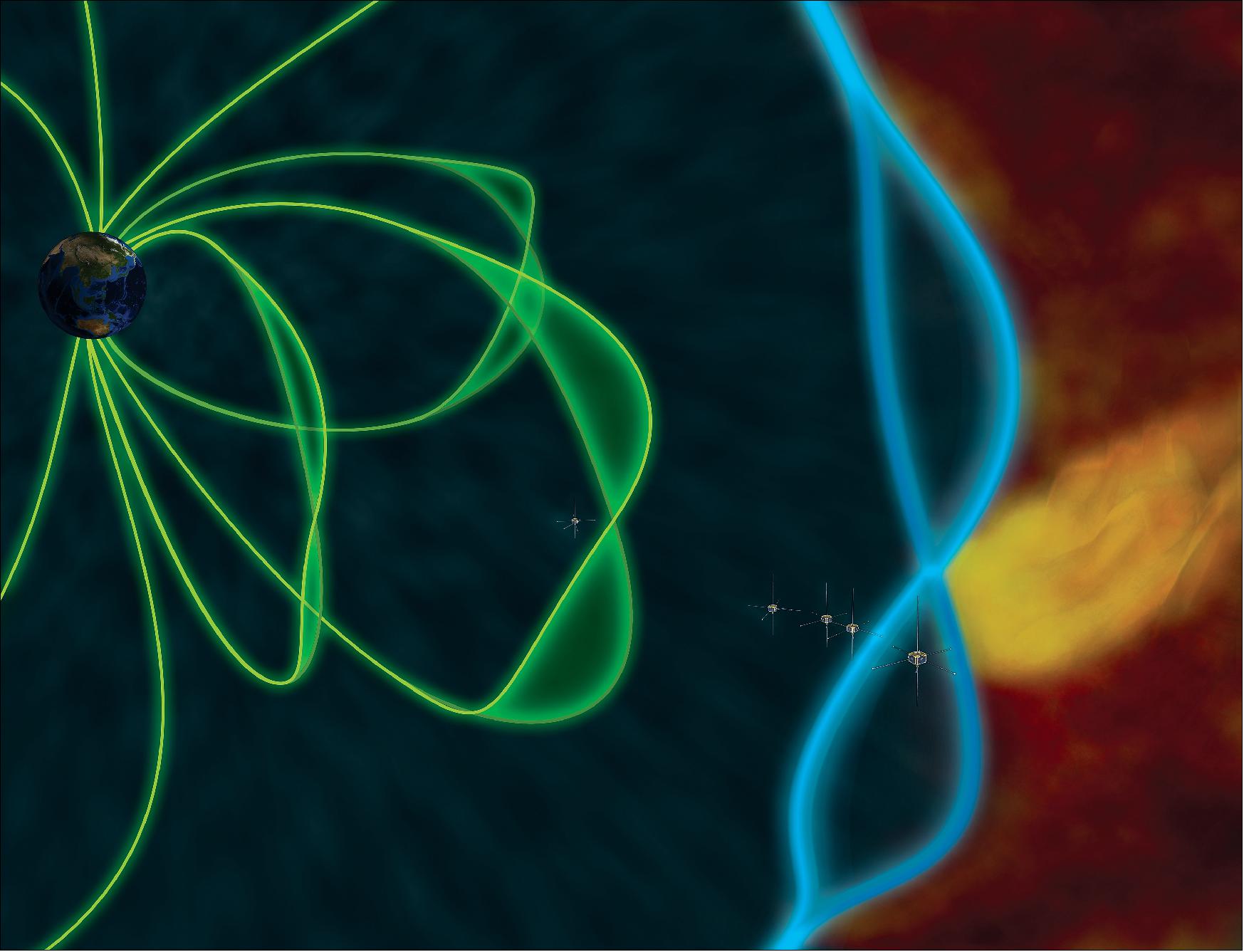
• January 29, 2018: For the first time, scientists have estimated how much energy is transferred from large to small scales within the magnetosheath, the boundary region between the solar wind and the magnetic bubble that protects our planet. Based on data collected by ESA's Cluster and NASA's THEMIS missions over several years, the study revealed that turbulence is the key, making this process a hundred times more efficient than in the solar wind. 23)
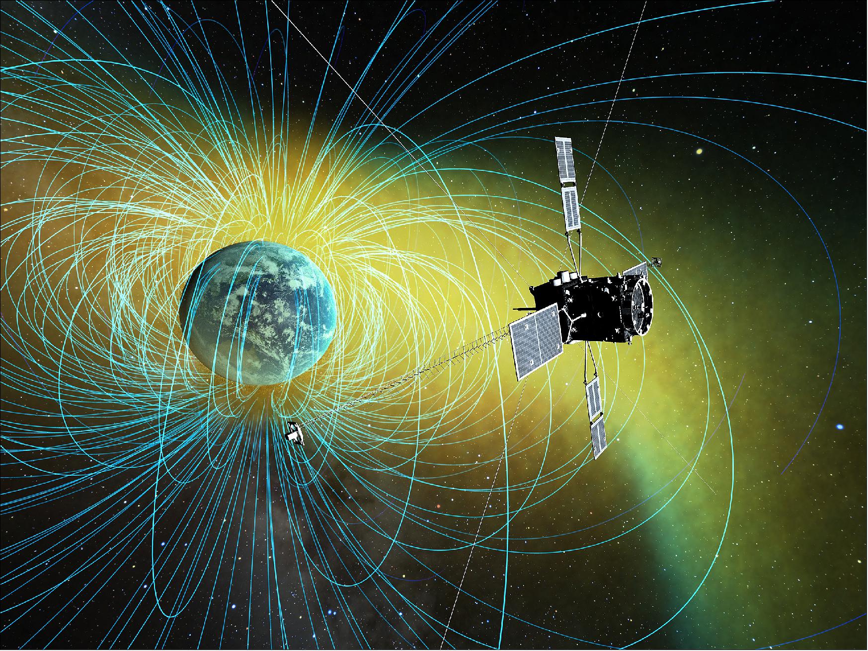
![Figure 30: The magnetosheath in Earth's magnetic environment [image credit: ESA (background and Cluster spacecraft); NASA (THEMIS spacecraft)]](https://eoportal.org/ftp/satellite-missions/t/Themis_021121/Themis_Auto22.jpeg)
- The planets in the Solar System, including our Earth, are bathed in the solar wind, a supersonic flow of highly energetic, charged particles relentlessly released by the Sun. Our planet and a few others stand out in this all-pervasive stream of particles: these are the planets that have a magnetic field of their own, and so represent an obstacle to the sweeping power of the solar wind.
- It is the interaction between Earth's magnetic field and the solar wind that creates the intricate structure of the magnetosphere, a protective bubble that shields our planet from the vast majority of solar wind particles.
- So far, scientists have achieved a fairly good understanding of the physical processes that take place in the solar wind plasma and in the magnetosphere. However, many important aspects are still missing regarding the interplay between these two environments and about the highly turbulent region that separates them, known as magnetosheath, where it is suspected that most of the interesting action happens.
- "To learn how energy is transferred from the solar wind to the magnetosphere, we need to understand what goes on in the magnetosheath, the 'grey area' between them," says Lina Zafer Hadid, from the Swedish Institute of Space Physics in Uppsala, Sweden. Lina is the lead author of a new study that quantifies, for the first time, the role of turbulence in the magnetosheath. The results are published in Physical Review Letters. 24)
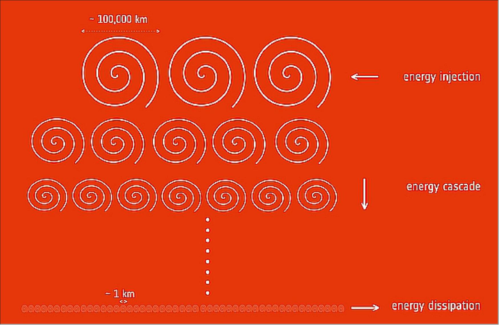
- "In the solar wind, we know that turbulence contributes to the dissipation of energy from large scales of hundreds of thousands of kilometers to smaller scales of a kilometer, where plasma particles are heated up and accelerated to higher energies," explains co-author Fouad Sahraoui from the Laboratory of Plasma Physics in France.
- "We suspected that a similar mechanism must be at play in the magnetosheath too, but we could never test it until now," he adds.
- The magnetosheath plasma is more turbulent, home to a greater extent of density fluctuations and can be compressed to a much higher degree than the solar wind. As such, it is substantially more complex, and scientists have only in recent years developed the theoretical framework to study the physical processes taking place in such an environment.
- Lina, Fouad and their collaborators combed through a vast volume of data collected between 2007 and 2011 by the four spacecraft of ESA's Cluster and two of the five spacecraft of NASA's THEMIS missions, which fly in formation through Earth's magnetic environment.
- When they applied the recently developed theoretical tools to their data sample, they were in for a big surprise.
- "We found that density and magnetic fluctuations caused by turbulence within the magnetosheath amplify the rate at which energy cascades from large to small scales by at least a hundred times with respect to what is observed in the solar wind," explains Lina.
- The new study indicates that about 10-13 J of energy is transferred per cubic meter every second in this region of Earth's magnetic environment.
- "We expected that compressible turbulence would have an impact on the energy transfer in magnetosheath plasma, but not that it would be so significant," she adds.
- In addition, the scientists were able to derive an empirical correlation that links the rate at which energy is dissipated in the magnetosheath with the fourth power of another quantity used to study the motion of fluids, the so-called turbulent Mach number. Named after Austrian physicist Ernst Mach, it quantifies the speed of fluctuations in a flow with respect to the speed of sound in that fluid, indicating whether a flow is subsonic or supersonic.
- While the energy transfer rate is tricky to determine unless using space probes that take in situ measurements, like the Cluster spacecraft sampling the plasma around Earth, the Mach number can be more easily estimated using remote observations of a variety of astrophysical plasma beyond the realm of our planet.
- "If this empirical relation turns out to be universal, it will be extremely useful to explore cosmic plasma that cannot be directly probed with spacecraft, such as the interstellar medium that pervades our Milky Way and other galaxies," says Fouad.
- The scientists are looking forward to comparing their results with measurements of the plasma surrounding other Solar System planets with an intrinsic magnetic field, for example using NASA's Juno mission, currently at Jupiter, and ESA's future Jupiter Icy Moons Explorer, and also the joint ESA-JAXA BepiColombo mission to Mercury that is scheduled for launch later this year.
- "It is very exciting that a study based on several years of Cluster data has found the key to address a major, long unsolved question in plasma physics," says Philippe Escoubet, Cluster Project Scientist at ESA.
• March 9, 2017: Every day, invisible magnetic explosions are happening around Earth, on the surface of the sun and across the universe. These explosions, known as magnetic reconnection, occur when magnetic field lines cross, releasing stored magnetic energy. Such explosions are a key way that clouds of charged particles — plasmas — are accelerated throughout the universe. In Earth’s magnetosphere — the giant magnetic bubble surrounding our planet — these magnetic reconnections can fling charged particles toward Earth, triggering auroras. 25)
- Magnetic reconnection, in addition to pushing around clouds of plasma, converts some magnetic energy into heat, which has an effect on just how much energy is left over to move the particles through space. A recent study used observations of magnetic reconnection from NASA's ARTEMIS (Acceleration, Reconnection, Turbulence and Electrodynamics of the Moon’s Interaction with the Sun) mission — to show that in the long tail of the nighttime magnetosphere, extending away from Earth and the sun, most of the energy is converted into heat. This means that the exhaust flows — the jets of particles released by reconnection — have less energy available to accelerate charged particles than previously thought. 26)
- When magnetic reconnection occurs between two clouds of plasma that have the same density, the exhaust flow is wildly unstable — flapping about like a garden hose with too much water pressure. However, the new results find that, in the event observed, if the plasmas have different densities, the exhaust is stable and will eject a constant, smooth jet. These differences in density are caused by the interplay of the solar wind — the constant stream of charged particles from the sun — and the interplanetary magnetic field that stretches across the solar system.
- These new results are key to understanding how magnetic reconnection can send particles zooming toward Earth, where they can initiate auroras and cause space weather. Such information also provides fundamental information about what drives movement in space throughout the universe, far beyond the near-Earth space we can observe more easily.
• On February 17, 2017, NASA's THEMIS mission marked its 10th anniversary on orbit. The spacecraft have now spent a decade discovering how mass and energy move through the near-Earth environment in order to determine the physical processes initiating auroras – and they’re still making new discoveries. 27)
- “THEMIS is morphing each year into a new journey of exploration,” said Vassilis Angelopoulos, principal investigator of THEMIS at the University of California, Los Angeles. “The instruments are as good as new and are still being utilized to expand NASA’s exploration of our space environment.”
- The magical night lights of the aurora are known to be caused by a space weather phenomenon known as a substorm. But prior to THEMIS, no one understood what triggered these substorms. Thanks to the mission, scientists now understand how the constant outpouring of solar material, called the solar wind, tangles Earth’s magnetic field, initiating the substorms that cause auroras. Scientists also understand the mysteries of why there are different type of auroras – like diffuse and pulsating auroras – much better now.
- THEMIS was initially launched as a five-satellite constellation, but in 2010, after the end of THEMIS’ prime mission, two of the spacecraft split off to start a new mission: ARTEMIS (Acceleration, Reconnection, Turbulence and Electrodynamics of the Moon’s Interaction with the Sun). ARTEMIS studies the moon and its space environment to help contextualize THEMIS discoveries while simultaneously trailblazing new science at the moon. Meanwhile, THEMIS continues studying substorms near Earth with three spacecraft.
- Ten years on, THEMIS is no longer alone. NASA’s Van Allen Probes, since 2012, and NASA’s MMS (Magnetospheric Multiscale) Mission, since 2014, study the near-Earth environment along with THEMIS to provide a wealth of observations on different aspects of near-Earth space and, in concert with other satellites in the Heliophysics System Observatory, provide a start-to-finish picture of physical processes in the region. THEMIS also has the ability to continue to adjust its orbit to better coordinate its measurements with the other missions and maximize its observational power.
• November 14, 2016: New observations from NASA's THEMIS mission show that the turbulent region known as the ion foreshock can accelerate electrons up to speeds approaching the speed of light. Such extremely fast particles have been observed in near-Earth space and many other places in the universe, but the mechanisms that accelerate them have not yet been concretely understood. 28) 29)
- The research finds electrons can be accelerated to extremely high speeds in a near-Earth region farther from Earth than previously thought possible – leading to new inquiries about what causes the acceleration. These findings may change the accepted theories on how electrons can be accelerated not only in shocks near Earth, but also throughout the universe. Having a better understanding of how particles are energized will help scientists and engineers better equip spacecraft and astronauts to deal with these particles, which can cause equipment to malfunction and affect space travelers.
- "This affects pretty much every field that deals with high-energy particles, from studies of cosmic rays to solar flares and coronal mass ejections, which have the potential to damage satellites and affect astronauts on expeditions to Mars," said Lynn Wilson, lead author of the paper on these results at NASA's Goddard Space Flight Center in Greenbelt, Maryland. The results describe how such particles may get accelerated in specific regions just beyond Earth's magnetic field and can gain energy through electromagnetic activity in the foreshock region itself.
- The THEMIS spacecraft found electrons accelerated to extremely high energies which lasted less than a minute, but were much higher than the average energy of particles in the region, and much higher than can be explained by collisions alone. Simultaneous observations from the additional Heliophysics spacecraft, Wind and STEREO, showed no solar radio bursts or interplanetary shocks, so the high-energy electrons did not originate from solar activity. "This is a puzzling case because we're seeing energetic electrons where we don’t think they should be, and no model fits them," said David Sibeck, co-author and THEMIS project scientist at NASA Goddard. "There is a gap in our knowledge, something basic is missing."
- The electrons also could not have originated from the bow shock, as had been previously thought. If the electrons were accelerated in the bow shock, they would have a preferred movement direction and location – in line with the magnetic field and moving away from the bow shock in a small, specific region. However, the observed electrons were moving in all directions, not just along magnetic field lines. Additionally, the bow shock can only produce energies at roughly one tenth of the observed electrons’ energies. Instead, the cause of the electrons’ acceleration was found to be within the foreshock region itself.
- "It seems to suggest that incredibly small scale things are doing this because the large scale stuff can't explain it," Wilson said. High-energy particles have been observed in the foreshock region for more than 50 years, but until now, no one had seen the high-energy electrons originate from within the foreshock region. This is partially due to the short timescale on which the electrons are accelerated, as previous observations had averaged over several minutes, which may have hidden any event. THEMIS gathers observations much more quickly, making it uniquely able to see the particles. Next, the researchers intend to gather more observations from THEMIS to determine the specific mechanism behind the electrons' acceleration.
• October 2015: Advances in our understanding of the changing space environment surrounding the Earth, commonly known as space weather, increasingly rely on prolonged simultaneous observations of the time varying conditions within the Sun-Earth system from various vintage points in space and from the ground. With nineteen operating solar, heliospheric, geospace, and planetary missions, the HSO (Heliophysics System Observatory) monitors key processes across the Solar System. Results from fortuitous conjunct observations have revealed coupling processes on multiple scales and demonstrated the potential of coordinated cross-scale multi-missions to quantify the driving mechanisms of the vast flows of energy and particles. 30)
- Since launch in February 2007 the NASA THEMIS mission has been tracking the flow of energy from the Earth’s midtail to the inner magnetosphere as a pathfinder for multi-mission coordination within the HSO. With the extended mission in 2010 the project team formed the combined missions THEMIS and ARTEMIS (Acceleration, Reconnection, Turbulence and Electrodynamics of the Moon’s Interaction with the Sun) utilizing our experience with the macro-scale constellation of the five THEMIS probes and their coordination with the GOBs (Ground Based Observatories). At the same time the project team integrated synchronized observations with other missions such as CLUSTER, GOES, and GEOTAIL in the science planning. Starting in 2012, the team has been coordinating the separations between the Earth orbiting THEMIS probes with the Van Allen Probes, NASA’s mission dedicated to study the radiation belts. The resulting continuous complementary observations are aiding the development of empirical models of the geoelectric field.
- With the implementation of NASA’s second magnetospheric constellation, the MMS (Magnetospheric Multiscale) mission, launched in March 2015 to study the conversion of magnetic energy into particle energy through magnetic reconnection, the opportunity arose for a truly multi-mission system-wide approach involving the HSO fleet and ground assets. In particular, the coordination of the orbit alignment of THEMIS and MMS allows prolonged simultaneous observations at key regions much needed to enhance our understanding of the space environment of the Earth and its dynamical response to external and internal influences.
- Although coordinating these two missions seems natural it came with unprecedented challenges. The THEMIS mission, already in orbit, has very limited resources for orbit re-design whereas the MMS mission came with various launch related uncertainties. In fact, the final launch day shift proved to be the most demanding. Just short of its late 2014 launch window, MMS experienced a launch delay that required a significant change in orientation of the launch trajectory with dramatic impact on the first cross-scale multi-mission alignment.
- The revised THEMIS-MMS alignment: The THEMIS mission is dedicated to study the energy and particle flow in the Sun-Earth system. The nominal mission focused on the time line of macroscale interactions during substorm onsets while the extended mission phases seek further understanding of our new findings. After zooming in on inner magnetosphere processes we now look at energy release mechanisms that occur beyond 10 RE and after substorm onset. The ARTEMIS probes either monitor solar wind input at lunar distances sunward of Earth or provide observations of plasma structures when crossing through the Earth magnetotail at lunar distances once per lunar cycle. The GOBs (Ground Based Observatories), high time resolution imagers and magnetometer across the northern American sector (Greenland, Canada, Alaska) will be fully utilized during the next two winter seasons when the THEMIS apogees line up in the tail and coincide with long polar nights.
- The MMS mission aims at the microphysics of magnetic reconnection in two magnetospheric regions by placing a small-scale tetrahedron inside the narrow layer from where the magnetic energy is released. This divides the mission into two phases. In phase 1 the MMS apogees are at 12 Re to maximize encounters with the dayside magnetopause. In phase 2 apogee altitudes will be at 25 Re to cross the midtail plasma sheet on the night side.
- Both missions have the optimal instrumentation to measure electric and magnetic fields and to characterize the plasma at the electron and ion kinetic scales in Earth’s space environment. Also equipped with onboard propulsion systems they are capable to alter the orbits. The original proposal combined the total of seven spacecraft into a cross-scale formation by placing the THEMIS probes at three vertices of a tetrahedron at medium scales and the MMS tetrahedral formation at small scales at the fourth vertex. Such a configuration would have allowed looking at electron and ion kinetics simultaneously at the reconnection side. The concept required aligning the lines of apsides of both missions. The team adjusted the rotation rate of the THEMIS lines of apsides by reducing perigee altitude.
Mitigating the fuel capacities and the launch uncertainties of MMS, the team started adjusting the rotation rate years ahead of the MMS launch and steadily fine-tuned it for an optimized alignment as the nominal MMS launch was approached. For a launch in fall of 2014 THEMIS would have been within a few degrees of the MMS line of apsides in both phases. The shift of the MMS launch into spring 2015 resulted in opposing apogees and the THEMIS fuel reserves became insufficient to overcome that much offset by reversing the drift of the THEMIS orbits alone. For a comprehensive analysis of the changes needed on both missions and in order to still facilitate the tetrahedral formation the remaining time was not sufficient and the team had to give up to study magnetic reconnection on multiple scales.
- The spring 2015 launch of MMS resulted in opposing apogees. Leaving the apogees of both missions about 180º apart provides the opportunity of prolonged simultaneous observations on the day and night sides with shifting emphasis on the coupling between plasma processes across the entire system. Additional aurora observations at very high time resolution in northern and southern polar regions are crucial in correlating local and global processes. Gaining this inside will greatly improve the capacity to predict space weather.
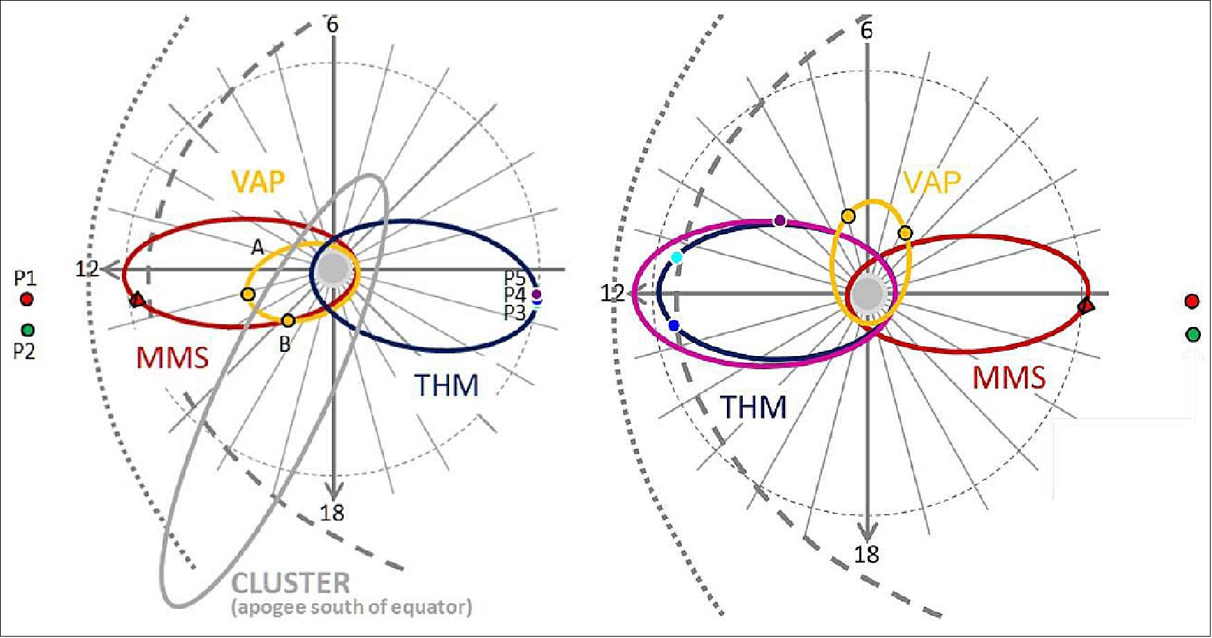
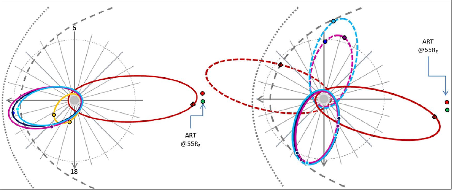
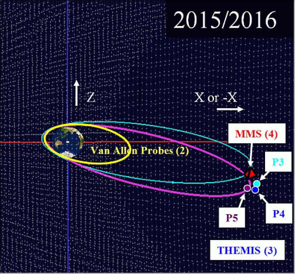
- Figures 35 and 36 summarize the evolution of the revised alignment of the THEMIS and MMS orbits where the lines of apsides precess counter clockwise at a rate primarily defined by apogee and perigee altitudes as well as inclination. Starting at 180º separation and with MMS on the dayside and THEMIS in the tail both missions will drift and alternate into MMS on the nightside and THEMIS on the dayside. By keeping both missions at similar altitudes we maintain this alignment throughout phase 1 of MMS. In phase 2, the MMS orbits will pass through the nightside at the higher apogee altitudes. THEMIS will continue to observe beyond 10 RE and progressively raise its apogees based on fuel reserves resulting in significantly different drift rates of the lines of apsides. By 2020, both missions will have moved out of the opposing apogee alignment as shown in Figure 36. This roughly 90º alignment is well suited to investigate important drivers of magnetic reconnection when THEMIS apogees are magnetically connected to the northern and southern polar regions.
- The THEMIS science goal for the years 2015 to 2020 is to improve our understanding of the coupling mechanism across the entire magnetospheric system such that quantifying the effect global processes impart onto local phenomena will be possible. In order to provide the crucial comprehensive coverage of the key regions on both sides of the Earth with regard to the sun at all kinetic scales, orbits are specifically designed with geocentric apogee altitudes from 10 to 16 RE. Inter-probe separations will vary from a few hundred over multiple thousand kilometers up to one or two Earth radii. Based on our most recent findings the consensus of the science community is that probe separations in the order of a few hundred kilometers in the xy-plane of the sun referenced frame, will be best suited to explore the microphysics of substorms. Taking advantage of the closely aligned THEMIS lines of apsides in 2015, the team starts with a clustered formation, and then facilitates probe specific apogee raises which will impart an intermittent increase of differential precession, and reassemble probes on a string-of-pearl formation in 2020. The latter will allow observations of particle and energy flow into the inner magnetosphere.
- In summary, the THEMIS mission has always been committed to align itself with current and future Heliophysics missions to advance our understanding of the dynamic interaction of the Earth’s magnetosphere with its space environment. For many years THEMIS has progressively utilized its resources to optimize conjunctions between all HSO assets culminating in the coordination of prolonged simultaneous multi-scale observations of reconnection processes with the new MMS mission. Challenges due to uncertainties related to launch have been overcome through relentless efforts in revising the science strategy for the first ever coordinated multi-mission constellation. As a result, the coming years will provide the most comprehensive opportunity to study the coupling processes system wide across multiple scales. For that the team has outlined the long term strategy through 2020 and the near term planning processes have put into place. The team is looking forward to realizing these ideas through the productive cooperation with the HSO community and the MMS team in particular (Ref. 30).
• July 2015: The THEMIS/ARTEMIS mission is approved by NASA to continue planning against the current budget guidelines. Any changes to the guidelines will be handled through the budget formulation process. The THEMIS mission will be invited to the 2017 Heliophysics Senior Review. 31)
• June 2015: All 5 of the THEMIS/ARTEMIS probes remain healthy and operating nominally. There are sufficient fuel reserves, including those required for de-orbit, to undertake the series of maneuvers proposed to place THEMIS in the optimum orbits for active coordination with the MMS (Magnetospheric MultiScale) mission, and for the scientific investigations necessitating a raising of the apogees of the near-Earth probes. The mission team report in the proposal all subsystems are effectively performing as good as new. 32)
- THEMIS data operations continue to be the exemplar for prompt dissemination of data products to the community, high quality of the data products, ease of access and data archiving. In addition, the dedicated THEMIS mission-developed software is being rolled out and used by other missions. Testament to the outstanding efficiency of the THEMIS data operation overall is provided by the scientific return from the worldwide community, which is currently running at around 150 THEMIS-based papers per year in the refereed scientific literature.
- The review panel noted the ongoing high level of impact and exceptional scientific output of the THEMIS mission, the strong involvement of the community in pursuing THEMIS mission science, and the core role which the THEMIS mission plays within the geospace element of the HSO, in particular for understanding the processing, input, transport and dissipation of energy from the solar wind into the magnetosphere and ionosphere. The panel noted the importance of funding for the THEMIS team to continue to support and coordinate community research. The panel also noted the strong commitment of the THEMIS team to the SPEDAS effort which is being prioritized and led by the team towards this goal.
- THEMIS science has continued to benefit from the powerful array of GB (Ground-Based) observatories built-up during the mission at high latitudes, and particularly in Canada. The coupling of magnetospheric flows into the high latitude ionosphere is detectable with these observations and thus they provide a more global picture of the magnetospheric dynamics. Recent GB observations suggest that small scale flows may rapidly cross the polar cap from day-to-night-side. Seeking to understand the magnetospheric counterpart and drivers for these flows motivates, at least in part, the over-guide request for funding to control the orbits of the 3 near-Earth THEMIS probes in order to keep them optimized with both the Canadian sector GB assets AND the newly launched MMS mission (launch March 13, 2015). In particular, this over-guide science implementation plan seeks to coordinate the THEMIS orbit with maneuvers along track such that they remain in opposition to MMS at apogee.
- The 4th and 5th THEMIS probes remain in orbit about the moon (formerly operated as the ARTEMIS mission). Over a period of 4 days per month, these spacecraft cross the more distant magnetotail (~60 RE) and thus contribute to the HSO (Heliophysics System Observatory)-related science questions above by observing the exhaust regions and/or providing a means to monitor the changing flux content of the magnetotail associated with the dynamics observed closer in. For the remainder of the month these probes sample the exterior solar wind plasma, contributing very significantly to our ability to monitor the direct and clean solar wind inputs from the region immediately upstream and which are responsible for driving magnetospheric dynamics.
• 2015: The ARTEMIS mission retasked two probes from the 5-spacecraft Heliophysics constellation THEMIS to study the interaction of the Moon with the space plasma environment. The two ARTEMIS spacecraft have now been in elliptical equatorial orbits around the Moon since mid-2011, and continue to operate flawlessly. Both probes are in very stable orbits, and the health of all instruments and the spacecraft remains very good. 33)
- Current ARTEMIS lunar investigations are focusing on measuring pickup ions from the exosphere, the electrostatic charging of the surface, the plasma wake, and the interaction of the solar wind with remanent crustal magnetic anomalies. ARTEMIS also uses lunar orbit as a platform to observe the solar wind and (around full Moon) the distant terrestrial magnetotail.
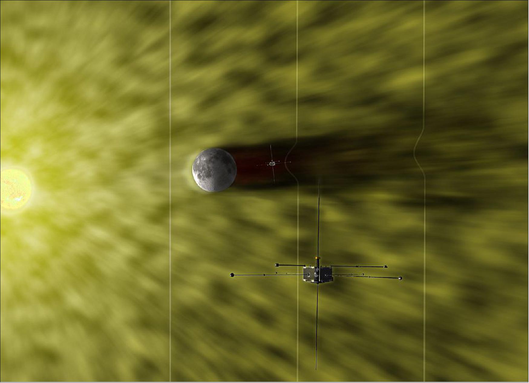
- Unlike the Earth, whose magnetic field deflects much of the incoming solar wind, the surface of the Moon absorbs most of the particles that the Sun sends its way. This creates a void behind the moon that gradually refills with plasma, forming a cone-shaped "lunar wake." However, the processes that govern refilling remain unclear, although models suggest they probably include a mixture of kinetic effects and effects particular to the dynamics of electrically conducting fluids. 34)
- Zhang et al. now provide a detailed characterization of the lunar wake and its relationship to the direction and strength of the solar wind. The researchers used two years' worth of data from the ARTEMIS (Acceleration, Reconnection, Turbulence, and Electrodynamics of the Moon’s Interaction with the Sun) mission to characterize many physical properties of the wake, including its magnetic properties, ion and electron densities, temperatures, pressures, and flow, while simultaneously monitoring the solar wind. 35)
- The scientists find that the lunar wake trails behind the Moon out to a distance at least 12 times its radius. The edges of the wake generate density waves that form disturbances that propagate both outward and inward like the wake of a boat. This process can mostly be explained by known principles about the flow of plasma. In contrast, they find that kinetic effects most likely explain the mid-wake maximum in ion and electron temperatures, which may result from high-energy particles refilling the wake faster than their low-energy counterparts.
- Notably, the researchers find that the angle between the direction of the solar wind and the orientation of the interplanetary magnetic field also influence the shape and character of the lunar wake, making it more ring-like for angles close to parallel and flatter for more perpendicular configurations. The scientists also find that the interplanetary magnetic field itself bulges toward the Moon inside the lunar wake, although they can’t yet identify the mechanism behind this observation.
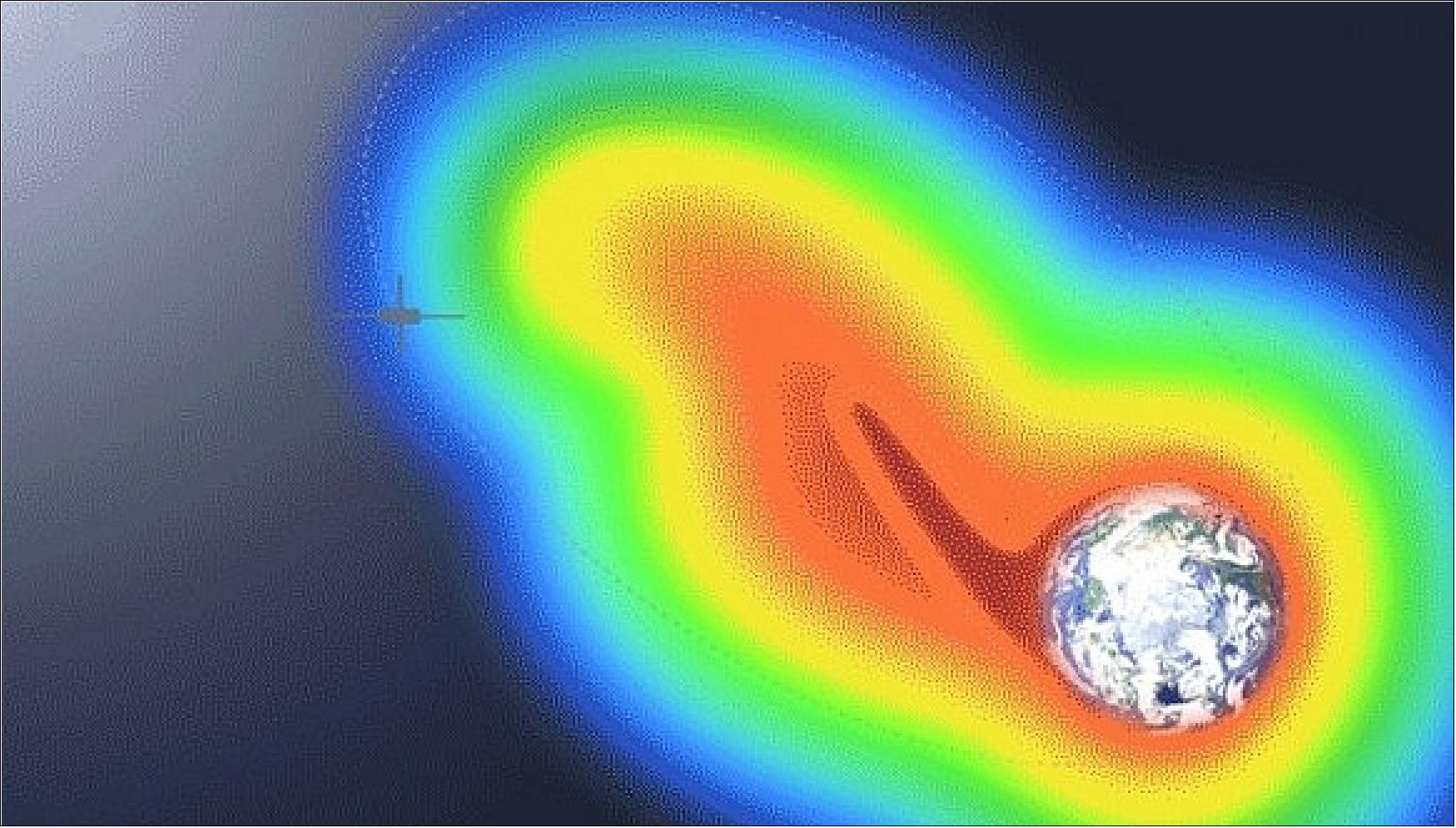
• March 2014: “The THEMIS-Low mission finds evidence of a new process protecting Earth from space weather.”
In the giant system that connects Earth to the sun, one key event happens over and over: solar material streams toward Earth and the giant magnetic bubble around Earth, the magnetosphere helps keep it at bay. The parameters, however, change: The particles streaming in could be from the constant solar wind, or perhaps from a giant cloud erupting off the sun called a coronal mass ejection, or CME. Sometimes the configuration is such that the magnetosphere blocks almost all the material, other times the connection is long and strong, allowing much material in. Understanding just what circumstances lead to what results is a key part of protecting our orbiting spacecraft from the effects of such space weather. 36)
Now, for the first time, a study shows that in certain circumstances a pool of dense particles normally circling Earth, deep inside the magnetosphere, can extend a long arm out to meet – and help block – incoming solar material.
In the words of Brian Walsh at NASA/GSFC: “ It’s like what you might do if a monster tried to break into your house. You’d stack furniture up against the front door, and that’s close to what the Earth is doing here. The material that is usually much nearer Earth stacks up against the outer boundary of the magnetosphere, throttling the interaction there and stopping solar material from entering.”
In the March 7, 2014, issue of Science, Walsh and his colleagues compared observations from the ground and in space during a solar storm on Jan. 17, 2013. 37) This was a fairly moderate solar storm caused by a CME (Coronal Mass Ejection) impacting Earth's magnetosphere for several hours. As the CME encountered the boundary of the magnetosphere, its magnetic fields and those around Earth realigned in a process called magnetic reconnection, which allowed energy and solar material to cross the boundary into the magnetosphere. NASA's three THEMIS (Time History of Events and Macroscale Interactions during Substorms) spacecraft, referred to as THEMIS-Low, were in the right place at the right time, flying through the magnetosphere's boundary approximately 45 minutes apart, and caught this interaction.
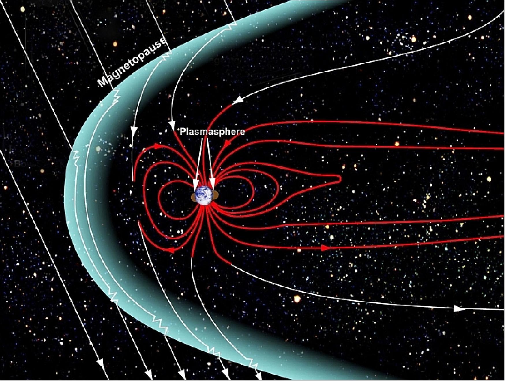
Closer to Earth, scientists could also study the sphere of cold dense gas at the very top of our atmosphere. This region is called the plasmasphere and it's made of what's known as plasma, a gas made of charged particles. GPS signals travel through the plasmasphere and they travel at different speeds depending on how thick or thin the plasmasphere is along the journey. Tracking the GPS radio signals, therefore, can help researchers map out the properties of the plasmasphere.
"A colleague who works with these kind of observations said I had to see some interesting data showing a plume from the ground," said Walsh. "And I typed in the dates and saw that it was a date when THEMIS was in the right position. So, for the first time, we could make a comparison."
THEMIS showed that the tongue of this cold, dense plasmasphere material stretched all the way up to the magnetic reconnection point where the CME had made contact with the magnetopause. The three sets of THEMIS observations demonstrated that the plume had a dramatic impact on the characteristics of the magnetic reconnection region.
A magnetic reconnection process becomes effective if it lasts long enough, then the whole magnetosphere gets involved. This tongue of the plasmasphere surges out, adding another layer of protection, curbing the magnetic reconnection.
As scientists try to better understand the space weather system around Earth, they rely on multipoint observations such as this to connect what's seen on the ground to what's seen in space. In this case THEMIS data connected to ground-based GPS TEC (Total Electron Content) data, but such combinations are increasingly being used to watch how Earth is affected by its closest star. Eventually such observations could lead to improvements in space weather predictions, which would be as useful for spacecraft operators as terrestrial weather forecasts are for us here on Earth.
• March 2014: The THEMIS (and ARTEMIS) spacecraft are doing very well. The project has yet to see any permanent radiation effects (only occasional resets due to Single Event Upsets) and the solar array power has barely moved below BOL values, this is attributed to the extra glass cover that was put on). New discoveries are happening every day. 38)
- In 2013, the THEMIS / ARTEMIS project proposed to a Senior Review Panel to perform maneuvers to align THEMIS and the future MMS (Magnetospheric MultiScale) in the sky so they form a greater tetrahedron (3THEMIS+MMS as a point) engulfing a larger tetrahedron (the MMS one). However, after the recent MMS launch delay to Feb/Mar of 2015, the project is revising the maneuver scenario so that it will still meet the launch restrictions/mission requirements for MMS.
- Between Sept. 25 and Oct. 22, 2013, the THEMIS project performed an orbit maneuver campaign for the three THEMIS probes (a total of 19 maneuvers). There were 4 orbit change maneuvers, one attitude, and one spin rate adjustment per probe. By lowering the perigee and apogee altitudes, the project further increased the orbital drift. These maneuvers were needed for the upcoming conjunctions with MMS in 2016 and 2017. 39)
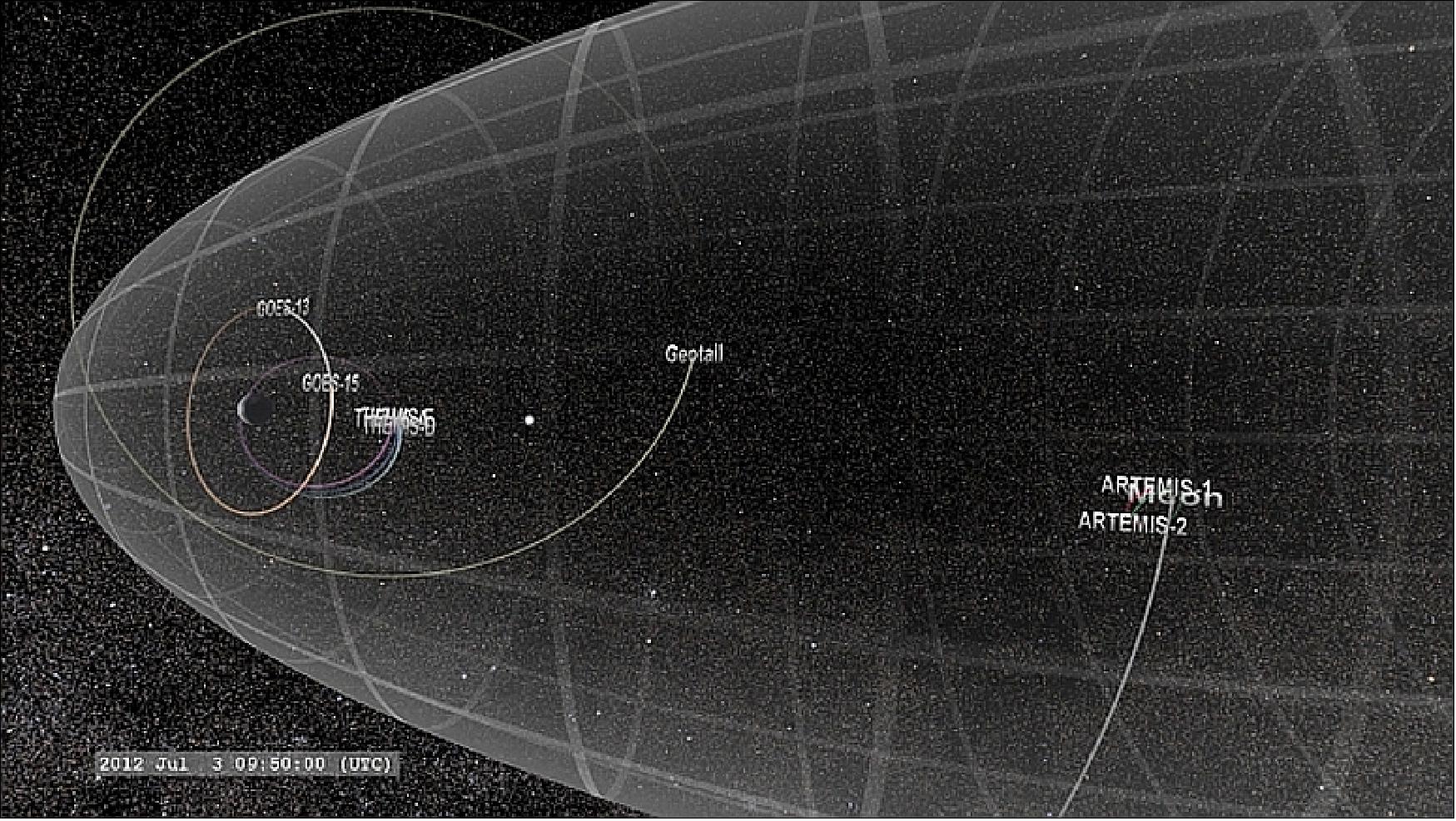
• September 2013: Analysis of a reconnection event on July 3, 2012.
Taking advantage of an unprecedented alignment of eight satellites through the vast magnetic environment that surrounds Earth in space, including NASA’s ARTEMIS and THEMIS, scientists now have comprehensive details of the energy’s journey through a process that forms the aurora, called a substorm. Their results, published in the journal Science on Sept. 27, 2013, showed that small events unfolding over the course of a millisecond can result in energy flows that last up to half an hour and cover an area 10 times larger than Earth. 40) 41) 42)
Trying to understand how gigantic explosions on the sun can create space weather effects involves tracking energy from the original event all the way to Earth. It’s not unlike keeping tabs on a character in a play with many costume changes, because the energy changes form frequently along its journey: magnetic energy causes eruptions that lead to kinetic energy as particles hurtle away, or thermal energy as the particles heat up. Near Earth, the energy can change through all these various forms once again.
Most of the large and small features of substorms take place largely in the portion of Earth’s magnetic environment called the magnetotail. Earth sits inside a large magnetic bubble called the magnetosphere. As Earth orbits around the sun, the solar wind from the sun streams past the bubble, stretching it outward into a teardrop. The magnetotail is the long point of the teardrop trailing out to more than 1.6 million km on the night side of Earth. The moon orbits Earth much closer, some 365,000 km away, crossing in and out of the magnetotail.
Tracking how such small events can have large-scale space weather effects requires observatories located throughout the whole system. To help with this endeavor, in July 2011, two of the five THEMIS spacecraft moved into place around the moon for a different vantage point on the magnetotail, through which the moon travels once a month. NASA renamed these two spacecraft the ARTEMIS mission. Once per year, all the orbits of the THEMIS and ARTEMIS spacecraft line up in the magnetotail together. On the most recent conjunction, in July 2012, a substorm occurred. During the same period, the joint GEOTAIL mission of JAXA/NASA and the GOES-13 and GOES-15 missions of NOAA were also in the magnetotail.
With eight spacecraft making observations at once, the scientists had a comprehensive view of how the energy in any given region moved around and transformed into other kinds of energy.
Scientists have observed much of the energy’s journey through a substorm before. When the solar wind streams off the sun it can connect with the front of Earth’s magnetosphere. As the two sets of magnetic fields come together, a process called magnetic reconnection turns the energy of the forward-moving solar wind into an explosion that sends particles and magnetic fields moving around the planet to the far side of Earth. Here, the fields reconnect again creating a burst that turns magnetic energy into acceleration of particles and heating. Just where and how this energy converted to particle movement, however, has been unclear.
The details of what happened next required observations from many spacecraft simultaneously. While the magnetic reconnection event itself happened in a specific place somewhere halfway between Earth and moon’s orbit in a region just a couple hundreds of miles across, this is not the main place where the energy was converted. Regions, labeled as “reconnection fronts” in the paper, surged away from the original reconnection point — one propagated toward Earth and one moved away, past the moon and down the magnetotail. These fronts are like sheets of current, a wall hurtling in each direction, continuing to convert energy for up to 30 minutes afterward. The energy moving in toward Earth helps to create the aurora and it also funnels into the giant donuts of radiation around Earth called the radiation belts.
The amount of energy released is equivalent to a 7.1 Richter scale earthquake. The fact that this energy can move around so dramatically is not in and of itself surprising. Scientists have certainly previously suggested such things based on computer models. But it is only with a fleet of spacecraft that scientists can confirm the location and exact nature of the process, not to mention learning something new such as how continuous and long term the energy conversion process is after the initial magnetic reconnection event.
• On Feb. 17, 2013, the THEMIS / ARTEMIS mission was 6 years on-orbit, all spacecraft are still operating. 43)
After 6 years, THEMIS has now traveled through more than 50 solar storms that caused particles in the outer radiation belts to either increase or decrease in number. Historically, it has been difficult for scientists to find commonalities between such occurrences and discover what, if anything consistently caused an enhancement or a depletion. With so many events to study, however, and a more global view of the system from several spacecraft working together – including, in this case, ground based observations and NOAA's GOES (Geostationary Operational Environment Satellites) and POES (Polar Operational Environmental Satellites) data, in addition to THEMIS data – a team of scientists led by Drew Turner at UCLA could better characterize what processes caused which results. 44)
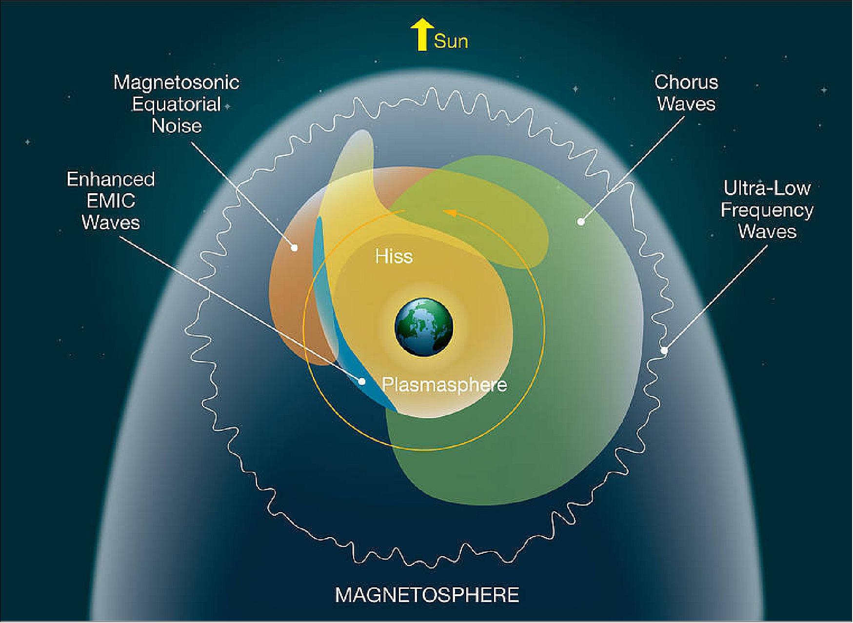
- Turner's group recently presented evidence linking specific kinds of electromagnetic waves in space – waves that are differentiated based on such things as their frequencies, whether they interact with ions or electrons, and whether they move along or across the background magnetic fields – to different effects. Chorus waves, so called because when played through an amplifier they sound like a chorus of singing birds, consistently sped up particles, leading to an increase in particle density. On the other hand, two types of waves known as hiss and EMIC (Electromagnetic Ion Cyclotron) waves occurred in those storms that showed particle depletion. Turner also observed that when incoming activity from the sun severely pushed in the boundaries of the magnetosphere this, too, led to particle drop outs, or sudden losses throughout the system. Such information is helpful to those attempting to forecast changes in the radiation belts, which if they swell too much can encompass many of our spacecraft. 45)
- Another group has a paper in print in 2013 based on 2008 data from the five THEMIS spacecraft in conjunction with three of NOAA's GOES (Geostationary Operational Environmental Satellites) spacecraft, and the ESA/NASA Cluster mission. Led by Michael Hartinger at the University of Michigan in Ann Arbor, this group compared observations at the bow shock where the supersonic solar wind brakes to flow around the magnetosphere to what happens inside the magnetosphere. They found that instabilities drive perturbations in the solar wind particles streaming towards the bow shock and that these perturbations can be correlated with another type of magnetized wave – ULF (Ultra Low Frequency) waves — inside the magnetosphere. ULF waves, in turn, are thought to be important for changes in the radiation belts. 46)
- A third interesting science paper from THEMIS's sixth year focused on features originating even further upstream in the solar wind. Led by Galina Korotova at IZMIRAN in Troitsk, Russia, this work made use of THEMIS and GOES data to observe the magnetosphere boundary, the magnetopause. The researchers addressed how seemingly small perturbations in the solar wind can have large effects near Earth. Wave-particle interactions in the solar wind in the turbulent region upstream from the bow shock act as a gate valve, dramatically changing the bow shock orientation and strength directly in front of Earth, an area that depends critically on the magnetic field orientation. The extreme bow shock variations cause undulations throughout the magnetopause, which, launch pressure perturbations that may in turn energize particles in the Van Allen radiation belts. 47)
Note: ARTEMIS (Acceleration Reconnection Turbulence, and Electrodynamics of Moon Interaction with the Sun) is an extension to the successful THEMIS (Time History of Events and Macroscale Interactions during Substorms) mission that has relocated two of the THEMIS spacecraft from Earth orbit to the Moon.
• In the spring of 2012, the two ARTEMIS spacecraft continue to collect solar wind, lunar wake, magnetospheric, and crustal magnetic anomaly data. Over the next few years the operations team will be executing approximately two maneuvers per year, per spacecraft, to control their periselene altitudes and enhance the low altitude transits while maintaining a safe distance from the surface. The team also plans to bring at least one of the ARTEMIS spacecraft into the near-terminator exospheric region in conjunction with NASA’s upcoming LADEE (Lunar Atmosphere and Dust Environment Explorer) mission. 48)
- ARTEMIS completed a two-year lunar transfer by way of multiple lunar gravity assists and a low-energy trans-lunar trajectory that culminated into EM L1 and EM L2 (Earth-Moon Libration point 2) and finally stable prograde and retrograde elliptical lunar orbits in July 2011. Between the two spacecraft, 170 maneuvers events were executed from the start of the mission extension to the final lunar placement with a 100% successful execution rate.
- In early May 2012, P2 will execute a short series of maneuvers to slow its spin rate down to P1’s rotational rate, with a goal of matching their spin synchronized data collection volumes and enhancing science operations. This maneuver sequence is being designed using a new spin control maneuver scheme that will not only spin the spacecraft down, but provide a beneficial attitude change to further mitigate the post-LOI (Lunar Orbit Insertion) thermal conditions and to take the place of an altitude control maneuver.
Many of the challenges encountered by the ARTEMIS mission were a result of taking two spacecraft created for Earth orbit into regions of space not encompassed in their original design. It is hoped that the experiences of the ARTEMIS team will help further the goals of future missions to the Moon and that the navigation data collected by the first spacecraft ever to continuously orbit Earth-Moon libration points will be of benefit to continued exploration of that interesting region of space (Ref. 48).
• In Feb. 2012, the THEMIS project celebrated 5 years of watching aurora and space weather. 49)
- On Feb. 13, 2012, one of the two probes, ARTEMIS P1 (formerly THEMIS-B), made the first lunar wake flyby of the mission. 50)
• As of late July 2011, the ARTEMIS mission is transferring two spacecraft from Lissajous orbits around Earth-Moon Lagrange Point No 1 (EML1) into highly-eccentric lunar science orbits with periods of roughly 28 hr. The ARTEMIS project plans to conduct a variety of scientific studies at the Moon using the on-board particle and fields instrument package. 51) 52) 53)
Many aspects of the transfer from Lissajous to the science orbits contribute to the novelty of the design. Firstly, the ARTEMIS probes have been the first spacecraft to fly Lissajous orbit near the Earth-Moon Lagrange points and thus, they are the first to approach a traditional lunar orbit from this location. Second, the ARTEMIS probes plan to routinely operate in the most eccentric lunar science orbits of any mission to date. These orbits are strongly perturbed by the Earth’s gravity, which makes for interesting three-body dynamics that are more typically considered in the context of outer planet moon orbiters. - Furthermore, ARTEMIS plans a number of different science investigations while in lunar orbit, many of which have particular trajectory implications that must be satisfied. Finally, P1 and P2 were built as low-cost Earth orbiters; the spacecraft capabilities, particularly in the area of available thrust and ΔV , are less robust than they may have been if the lunar mission had been planned before launch (Ref. 51).
Since ARTEMIS is both a heliophysics and a planetary science mission, a wide range of science observations are planned for during the lunar orbit phase, including:
- 3-D mapping of the lunar wake induced by the solar wind at a range of downstream distances
- Measurements of selected lunar crustal magnetic anomalies
- Measurements of the lunar exosphere and surface charging
- Coordinated measurements with NASA’s forthcoming LADEE (Lunar Atmosphere and Dust Environment Explorer) mission to characterize the near-terminator exosphere.
The above science measurement objectives directly drive the design of the lunar science orbit and approach from Lissajous. To achieve the desired lunar wake measurements, the two spacecraft should be in highly eccentric orbits that precess at rates different from each other and from the Sun direction. The mission duration should be long enough so that a full range of measurement altitudes and relative orientations can be achieved. To measure the crustal magnetic anomalies, periapsis altitudes must be less than 50 km and in the vicinity of the anomaly. Each anomaly dictates a minimum orbit inclination required to achieve this. Measurements of the lunar exosphere require a range of altitudes and orientations with respect to the Sun. To coordinate near-terminator exosphere investigations with LADEE, an ARTEMIS spacecraft must be below 200 km within 30º of the dawn terminator at least once during the 3-month LADEE science mission scheduled for 100 days between July 2013 and March 2014 (depending on launch date). Finally, to maximize the quantity of all measurements, the orbits should have long-term stability (Ref. 51).
• In July 2011, the two ARTEMIS Probes are in lunar orbit. The first spacecraft entered lunar orbit on June 27, and the second on July 17, 2011. With two spacecraft orbiting in opposite directions, the project can acquire a full 3-D view of the structure of the magnetic fields near the moon and on the lunar surface. 54) 55)
• In late June 2011, the two Probes have almost arrived at the moon. It took one and a half years, over 90 orbit maneuvers, and – wonderfully – many gravitational boosts and only the barest bit of fuel to move two spacecraft from their orbit around Earth to their new home around the moon. 56)
- On January 9, 2011, ARTEMIS P1 jumped over the moon and joined ARTEMIS P2 on the side of the moon closest to Earth. Now the last steps are about to begin.
- On June 27, 2011, P1 will spiral in toward the moon and enter lunar orbit. On July 17, P2 will follow. P2 will travel in the same direction with the moon, or in prograde; P1 will travel in the opposite direction, in retrograde.
Along their travels, the spacecraft have been through orbits never before attempted and made lovely curlicue leaps from one orbit to the next. In the summer of 2011, the two ARTEMIS spacecraft — which began their lives as part of the five-craft THEMIS mission studying Earth's aurora – will begin to orbit the moon instead.
Even with NASA's decades of orbital mechanics experience, this journey was no easy feat. The trip required several maneuvers never before attempted, including several months when each craft moved in a kidney-shaped path on each side of the moon around, well, nothing but a gravitational point in space marked by no physical planet or object.
• On October 22, 2010, the ARTEMIS-P2 probe settled into a temporary "Lagrange-point" orbit. 57)
Over the next several years, ARTEMIS will help space scientists understand how the earth’s magnetosphere is shaped by the strong solar wind at the distance of the moon and also how the moon’s own tiny magnetic field interacts with the solar wind. Using simultaneous measurements of particles and electric and magnetic fields from two locations, ARTEMIS will provide the first three-dimensional perspective of how energetic particle acceleration occurs near the moon’s orbit, in the distant magnetosphere, and in the solar wind.
• In August 2010, ARTEMIS-P1 became the first spacecraft to navigate to and perform stationkeeping operations around the Earth-Moon L1 and L2 Lagrangian point (Ref. 80).
The ARTEMIS mission is an absolute success and this success can be attributed to the use of several tools to validate and confirm the planning and execution of maneuvers necessary to transit a dynamically challenging environment. The combined method of optimization with manifold verification, thought not new, is a substantial leap in the operational design of such missions. With the completion of the ARTEMIS trajectory, a viable multi-tiered process and trajectory feasibility is demonstrated. The opportunities of the ARTEMIS mission provide the space community with the first ever completed design from Earth to the Earth-Moon L2 and L1 Lissajous orbits. The ARTEMIS P1 spacecraft has completed its transfer and is in now in the Earth-Moon L2 Lissajous trajectory; the P2 spacecraft is on-track for Earth-Moon libration orbit insertion (Ref. 81).
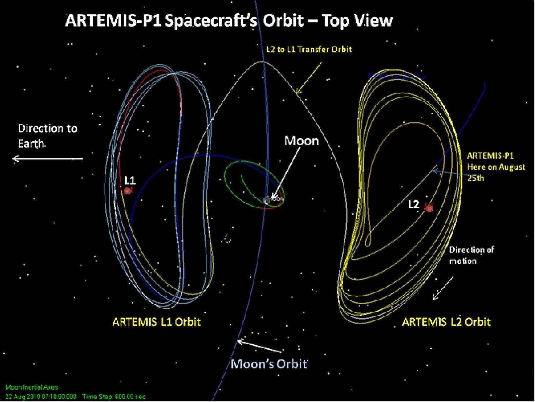
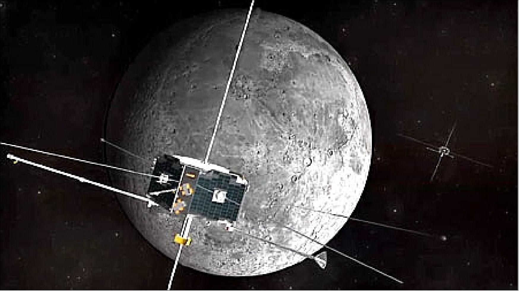
• The THEMIS/ARTEMIS constellation is operating nominally in 2010. All probes are very healthy and collecting science data. The fuel reserves allow for an ambitious mission extension. The THEMIS mission has answered the longstanding fundamental questions concerning the nature of the substorm instabilities that abruptly and explosively release solar wind energy stored within the Earth’s magnetotail.
• The extended science mission will keep the three innermost THEMIS spacecraft in elliptical Earth orbits and maneuver the two outermost spacecraft to the lunar regime. In July 2009, the THEMIS mission split into two missions: 58)
- The first, THEMIS-Low, consisting of the three inner probes (P3, P4, P5), will continue to study the Earth's space environment.
- The two outer probes, P1 and P2, will explore the space environment of the moon. This new mission was renamed to ARTEMIS (Acceleration Reconnection Turbulence, and Electrodynamics of Moon Interaction with the Sun). The ARTEMIS mission is a collaborative effort between NASA/GSFC, UCB (University of California at Berkeley), and NASA/JPL (Jet Propulsion Laboratory). Note: see ARTEMIS chapter at end of file. 59) 60) 61)
At the request of the Principal Investigator (PI), analysts at the JPL designed transfer trajectories for both P1 and P2 to insert them into Earth-Moon libration point orbits. The maneuver plan includes a series a propulsive ORMs (Orbit-Raising Maneuvers) to position each spacecraft for a series of lunar and Earth gravity assist maneuvers. The translunar orbit injections for P1 and P2 will occur in January and March 2010, respectively, with lunar libration point orbit captures in August and October 2010. After collecting science data in the Lissajous orbits for several months, the two spacecraft will be maneuvered into selenocentric orbits (Ref. 59).
The ARTEMIS science mission begins once each spacecraft is inserted into its Lissajous orbit. Since L1 and L2 are unstable Lagrangian points, the operations team must perform frequent stationkeeping maneuvers to maintain each spacecraft in the Lissajous orbits for several months.
Lunar phase: At the completion of the Lissajous orbit phase, the ARTEMIS satellites will perform large orbit maneuvers to depart the lunar libration point orbits and be captured into selenocentric orbits.
ARTEMIS is considered a pathfinder for future missions operating in the lunar libration point regions and will provide unprecedented science observations of the magnetosphere in selected lunar regimes.
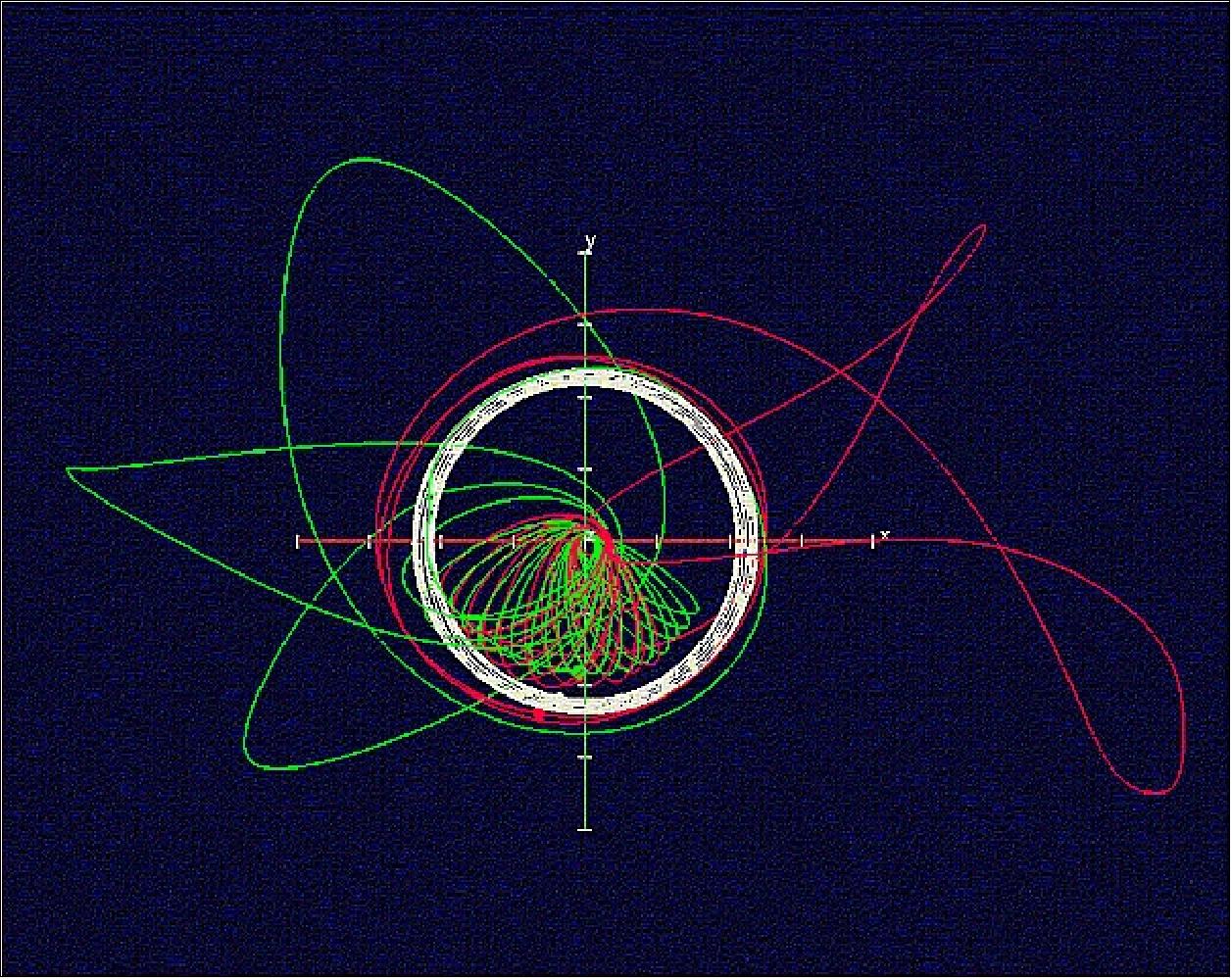
• With a design life of 2 years, THEMIS completed also its primary mission goal in April 2009 - having achieved its primary objectives of establishing when and where the substorms begin. Officially, the THEMIS prime mission was completed in July, 2009 after two successful observing seasons in the Earth’s magnetospheric tail.
NASA has extended the THEMIS mission to the year 2012. - Also, a new mission was designed of the two outer probes of the constellation, P1 and P2, referred to as ARTEMIS (Acceleration Reconnection Turbulence, and Electrodynamics of Moon Interaction with the Sun). The goal is to maneuver the two spacecraft into the Earth-Moon Lagrangian points and eventually into lunar orbit - to observe the same phenomena as before but from a different perspective. 62)
The planning for the ARTEMIS mission started in 2008. The vast experience, ingenuity and dedication of the THEMIS project team made this extended mission to the moon possible. This represents an extra science bonus that could not be foreseen in the early project phases of THEMIS (see ARTEMIS at end of file).
• Spacequakes: A spacequake is a temblor in Earth's magnetic field. It is felt most strongly in Earth orbit, but is not exclusive to space. The effects can reach all the way down to the surface of Earth itself. 63)
In 2007, THEMIS discovered the precursors of spacequakes. The action begins in Earth's magnetic tail, which is stretched out like a windsock by the solar wind. Sometimes the tail can become so stretched and tension-filled, it snaps back like an over-torqued rubber band. Solar wind plasma trapped in the tail hurtles toward Earth. On more than one occasion, the five THEMIS spacecraft were in the line of fire when these "plasma jets" swept by. Clearly, the jets were going to hit Earth. But what would happen then? The fleet moved closer to the planet to find out.
According to THEMIS, the jets crash into the geomagnetic field some 30,000 km above Earth's equator. The impact sets off a rebounding process, in which the incoming plasma actually bounces up and down on the reverberating magnetic field. Researchers call it "repetitive flow rebuffing." It's akin to a tennis ball bouncing up and down on a carpeted floor. The first bounce is a big one, followed by bounces of decreasing amplitude as energy is dissipated in the carpet.
The THEMIS team has studied the phenomenon of spacequakes for several years and continues to do so in 2010. The surprise is plasma vortices, huge whirls of magnetized gas as wide as Earth itself, spinning on the verge of the quaking magnetic field (Ref. 63).
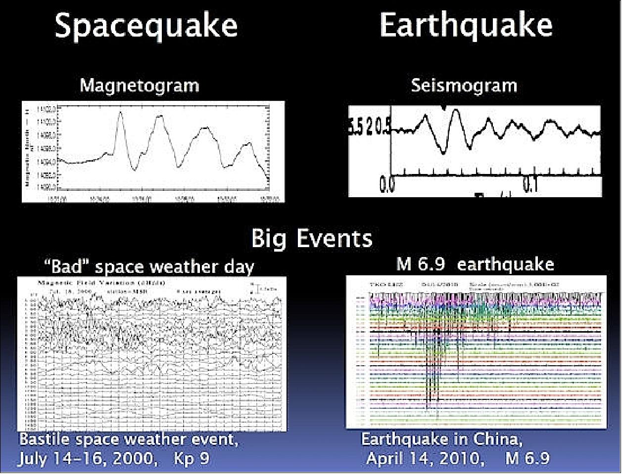
• A network of ASIs (All-Sky Cameras) deployed around the Alaskan/Canadian Arctic region in support of NASA's THEMIS mission has made a startling discovery about the Northern Lights. Sometimes, vast curtains of aurora borealis collide, producing spectacular outbursts of light. The 20 ASIs photographed auroras from below while the spacecraft sampled charged particles and electromagnetic fields from above. Together, the on-ground cameras and spacecraft could see the action from both sides and were able to piece together cause and effect. In 2009, Toshi Nishimura of UCLA assembled continent-wide movies from the observations of the individual ASI cameras. 64) 65) 66)
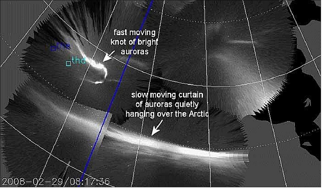
National Science Foundation-funded radars located in Poker Flat, Alaska, and Sondrestrom, Greenland, confirm this basic picture. They have detected echoes material rushing through Earth's upper atmosphere just before the auroras collide and erupt. The five THEMIS spacecraft also agree. They have been able to fly through the plasma tail and confirm the existence of lightweight flows rushing toward Earth.
The explosions of light, researchers believe, are a sign of something dramatic happening in the space around Earth—specifically, in Earth's "plasma tail." The same magnetic field that holds the tail together also connects it to Earth's polar regions. Because of this connection, watching the dance of Northern Lights can reveal much about what's happening in the plasma tail.
• On Feb. 16, 2009 the constellation was in orbit for 2 years. THEMIS has now fully accomplished its baseline objectives by completing the full second year's worth of magnetotail observations. Despite the extended Solar Minimum, solar wind energy coupling was strong and frequent enough to enable observations of at least two dozen substorms. THEMIS P1 and P2's tail orbits were changed in order to increase current sheet encounters, with excellent results in the data. In addition, there have been 3 second resolution full angular distributions of electrons 12 hrs per orbit on P1 and P2 in the tail season for ~3 weeks, while P3, 4, 5 stayed in that mode since mid-February. The resulting data recovery from all probes is about twice what was initially promised. The scientific potential of the dataset is astounding.
The flight data and feedback from various organizations have confirmed robust spacecraft validation that can survive multiple attitudes in highly elliptical orbits as designed. The flight telemetry has shown consistency in the data between the probes in various orbits demonstrating the high quality and workmanship of the probes. In addition, probe bus design limits have been consistently nominal throughout launch, early orbit, and the mission phases. 67)
• Using data from NASA's THEMIS mission, a team of University of Alberta researchers has pinpointed the impact epicenter of an earthbound space storm as it crashes into the atmosphere, and given an advance warning of its arrival. The team uses ground-based observatories spread across northern Canada and the five satellites of the THEMIS mission to detect magnetic disturbances as storms crash into the atmosphere. Using a technique the researchers call "space seismology," they look for the eye of the storm hundreds of thousands of miles above Earth. 68)
• Regarding science returns, NASA reports researchers have discovered that an explosion of magnetic energy a third of the way to the moon powers substorms, sudden brightenings and rapid movements of the aurora borealis, called the Northern Lights. The culprit turns out to be magnetic reconnection, a common process that occurs throughout the universe when stressed magnetic field lines suddenly ”snap” to a new shape, like a rubber band that's been stretched too far. 69)
• At a Press Conference of the EGU (European Geosciences Union) General Assembly Meeting in Vienna, Austria (April 23, 2009), the researchers Andreas Keiling, Karl-Heinz Glaßmeier, and Olaf Amm reported: “NASA's THEMIS spacecraft discovered that these flow vortices, or “space tornados”, generate currents of more than one hundred thousand A (ampere) in space and channel them into the ionosphere. The flow vortices are composed of rotating clouds of charged particles, called plasma, with embedded twisted magnetic field lines. Located about forty thousand miles away from Earth, they span a volume of approximately the size of the Earth or larger.”
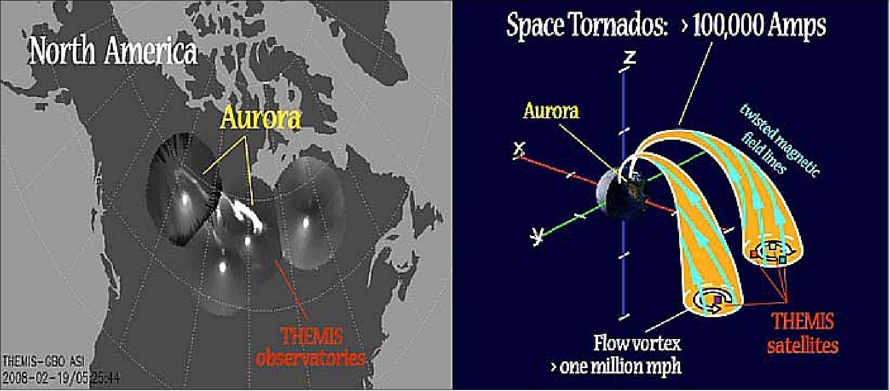
• On March 5, 2008, a little more than one year following launch, the three hour eclipse probe bus performance was demonstrated without issue during the P1 orbit. It was found that the probes were consistent in performance in various orbits and sun attitudes.
• At the end of Feb. 2008, the THEMIS constellation had observed 154 hours of four-probe conjunctions (the requirement was 94 hours), during which it observed 57 substorms. Of these 57 substorms, about 6-10 were observed from an excellent vantage point during the period Feb 02-26, 2008. During the first tail season, THEMIS accomplished about 200 hours of four-probe conjunctions and caught in excess of five dozen substorms, a dozen of which were pristine vantage points within the meridian.
• EFI deployment operations for the entire constellation were completed on 14 January 2008 with the deployment of THEMIS-A axial booms. This followed the deployment of THEMIS-A spin planes booms the previous week. In total, the EFI had nominal deploys of 20 wire boom and 10 stacer boom systems. Hence, by mid January 2008, less than one year after launch, the constellation was fully configured for science data acquisition in the primary observing season.
• Between early September and early November 2007, four of the five probes were maneuvered into their synchronized mission orbits with 1, 2 and 4-day periods, and with their lines of apsides aligned along the Earth’s magnetospheric tail in preparation for the primary observing season in the winter of 2007/2008. Orbital conjunctions allowing multiprobe measurements to be made at various distances within the magnetotail occurred every 4 days during this observing season. The fifth probe, acting as an on-orbit spare, was maneuvered into its 4/5-day period orbit in December 2007, once the four primary probes were completely deployed in their mission orbits.
• During the summer of 2007, the spacecraft were in a “coast phase” (July 1 to Aug. 31, 2007) collecting information about the interaction of the solar wind and the Earth's magnetic field.
• March 2007: The first science observations from the spacecraft were obtained on March 23, during a disturbance in the Earth's magnetic field known as a substorm. The multipoint spacecraft and dedicated ground observatories allowed researchers to track the development of the substorm via a proof-of-concept study demonstrating novel techniques that will be used throughout the course of the mission. All 25 instruments on each spacecraft have been operating well ever since.
• After launch the five THEMIS spacecraft were deployed into a “string-of-pearls” configuration on near-identical highly elliptical orbits with periods of 31 hours.
Sensor complement
The five spin-stabilized (Tspin = 3 s) Probes carry identical suites of electric field, magnetic field, and particle instruments. The THEMIS instruments measure particles and fields on orbits which optimize tail-aligned conjunctions over North America. Ground observatories time auroral breakup onset. Three inner Probes at ~10 RE monitor the current disruption onset, while two outer Probes, at ~ 20 and 30 RE respectively, remotely monitor plasma acceleration due to lobe flux dissipation.
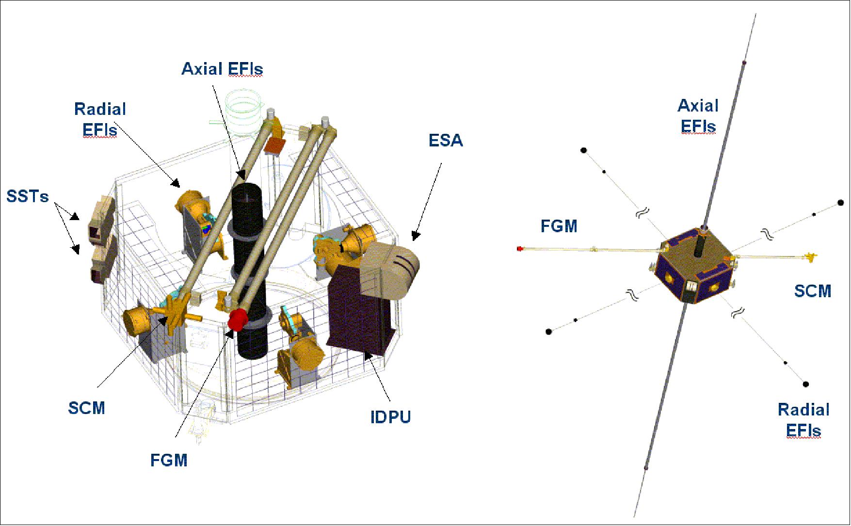
FGM (Fluxgate Magnetometer)
FGM is a triaxial fluxgate instrument provided by Germany [DLR, TUBS (Technical University of Braunschweig)], and Austria [ASA, IWF (Institut für Weltraumforschung)]. FGM has a flight heritage on AMPTE/IRM (1985), Phobos (1988), Interball (1992), Equator-S (1997), MIR (1998), Rosetta (2004), and Venus Express (2007). FGM measures the 3D ambient magnetic field. The objectives are to: 1) Measure DC and low frequency perturbations of the magnetic field, 2) Time wave and structure propagation between Probes, 3) Provide information on plasma currents based on instantaneous magnetic field differences on two or more Probes, separated by > 0.2 RE.
FGM is mounted on a 2 m deployable boom. The FGM unit consists of two orthogonal ring-core elements of different diameter, made of an ultra-stable 6-81-Mo permalloy band (2 mm x 20 µm), fixed within a bobbin. The unit is mounted on a 2 m double-hinge carbon epoxy boom with FAST and Lunar Prospector heritage. The electronics consist of the driver and control circuits, on a 10 x 12 cm2 board within the IDPU (Instrument Data Processing Unit). The controller controls digital excitation, data acquisition, feedback and compensation making the device low power. Its low noise permits easy intercalibration with the search-coil magnetometer at frequencies of~10 Hz. 70) 71)
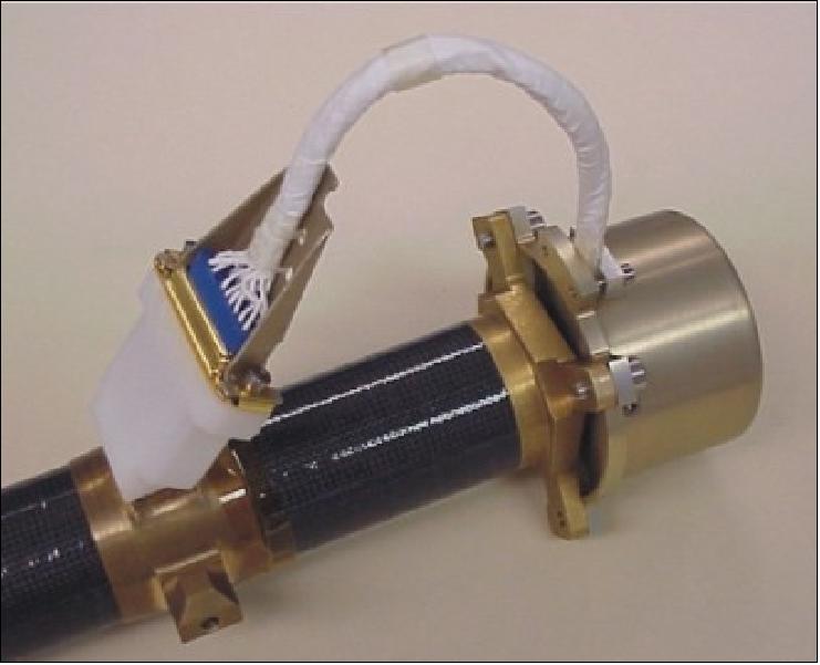
FGM calibration: Although a 1 nT absolute accuracy requirement is achievable with independent sensor calibration, it is important to ascertain that two separate Probes provide identical values when properties of the medium are steady. Once per orbit calibration data are acquired at 32Hz to determine (on individual Probes) zero levels, gains, and sensor orientation.
ESA (Electrostatic Analyzer)
ESA was designed and built at UCB/SSL. The ESA instrument has a flight heritage on the following missions: AMPTE/IRM, Giotto, FAST, WIND, and Cluster. The objective is to measure electrons and ions with high time resolution. The science requirements are to measure:
• Plasma moments to within 10%, at high time resolution (10 s or better) for inter-Probe timing studies
• Instantaneous differences in velocity and ion pressure between Probes, to estimate the scale size of transport, the size and strength of flow vortices and the pressure gradient
• Distribution functions of ions and electrons, to ascertain the presence of free energy sources.
ESA consists of an ion spectrometer and an electron spectrometer to make detailed distribution function measurements; in addition, there are electron-stepped ESAs to make very high time resolution electron measurements with lower energy and angle resolution.
Both the ion and the electron ESA units have a look direction of 180º in elevation, split in eight, 22.5º bins (one per anode). Measurements over a 4 π steradian, are made once per spin as the Probe rotates. The particles are selected in E/q (where q is the charge) by a sweeping potential applied in 32 steps, 32 times/spin (32 azimuths) between the outer (0 kV) and inner (~0-3 kV) concentric spheres and are focussed onto an MCP pair arranged in a Chevron configuration. On-board moment, pitch angle, and averaging computations are implemented at the IDPU. These operations routinely utilize FGM and SST data (to ensure correct values when the peak flux extends beyond the plasma instrument energy range). 72)
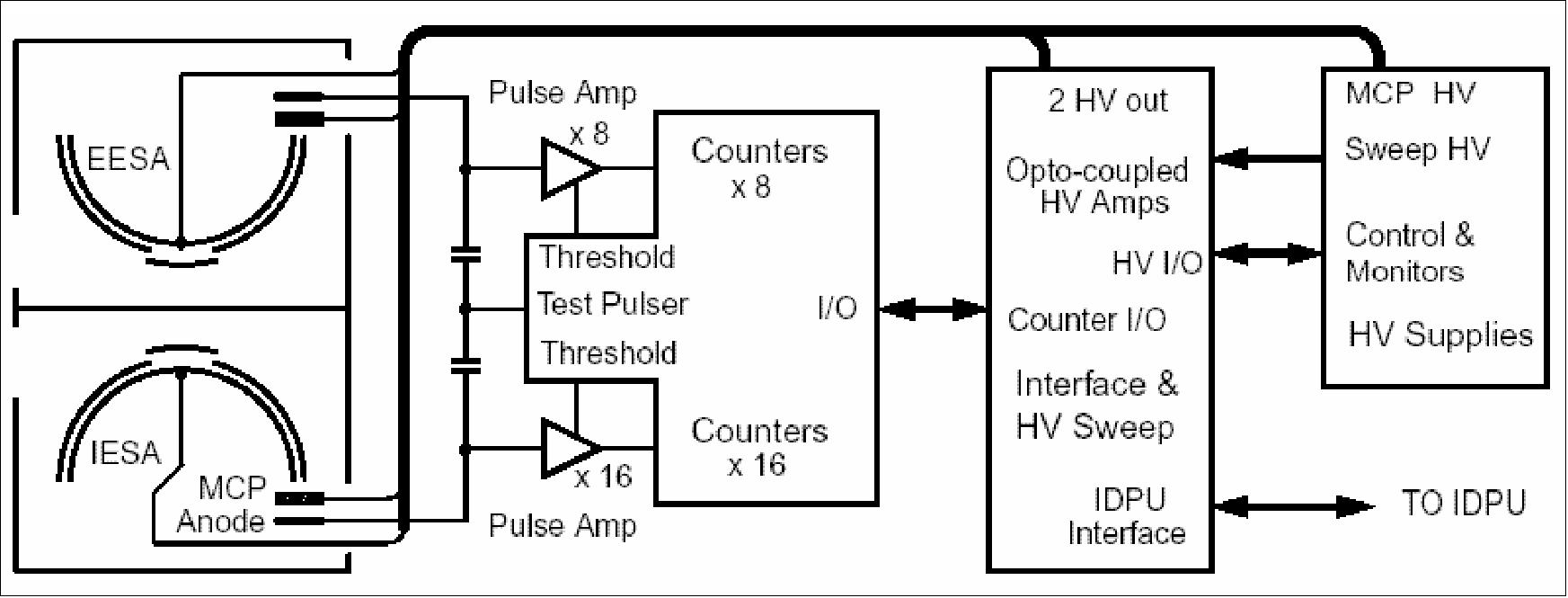
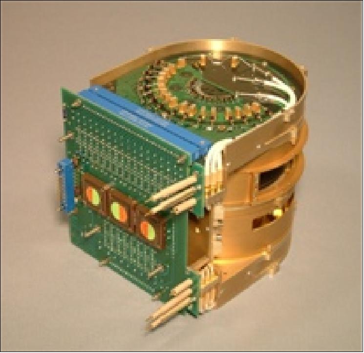
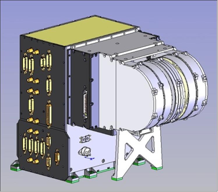
SST (Solid State Telescope)
SST was built by UCB. SST has a flight heritage on ISEE-1, -2, -3 and WIND. The objective is to measure the super-thermal part of the ion and electron distributions. The detector operation is very similar to the SST telescope pairs flown on WIND. Each Probe carries two such pairs. The SST geometric factors are optimized for THEMIS: They are WIND-like for THEMIS's high altitude apogees but a mechanical pin-hole attenuator reduces the geometric factor by a factor of 100 when fluxes get high close to Earth. The electronics are comprised of highly integrated version of WIND electronics chain afforded by FPGAs and Amptecs. The primary science needs for the SST are: 73)
1) To perform remote sensing of the tailward-moving current disruption boundary (at P3, P4, P5)
2) To measure the time-of-arrival of superthermal ions and electrons (30-300 keV, at 10 s resolution or better) during injections, and ascertain the Rx onset time (P1, P2).
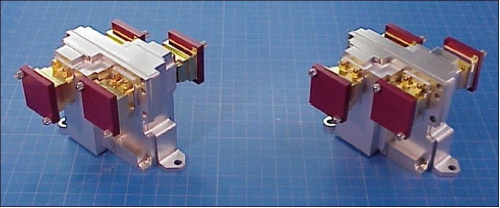
Instrument: Each double-ended telescope unit is equipped with three stacked, fully depleted, passivated, ion-implanted, 1.5 cm2 silicon detectors. The center (T) detector is 500 µm thick, while the outside (O & F) detectors are 300 m thick. The two detector pairs are mounted such that two telescope units point on the spin-plane (~ecliptic), one points above and the other below the spin-plane. One of the two spin-plane telescopes has detectors of area 0.075 cm2 and provides a geometric factor 20 times smaller that all the others to ensure no saturation at times of very high flux levels near the radiation belts.
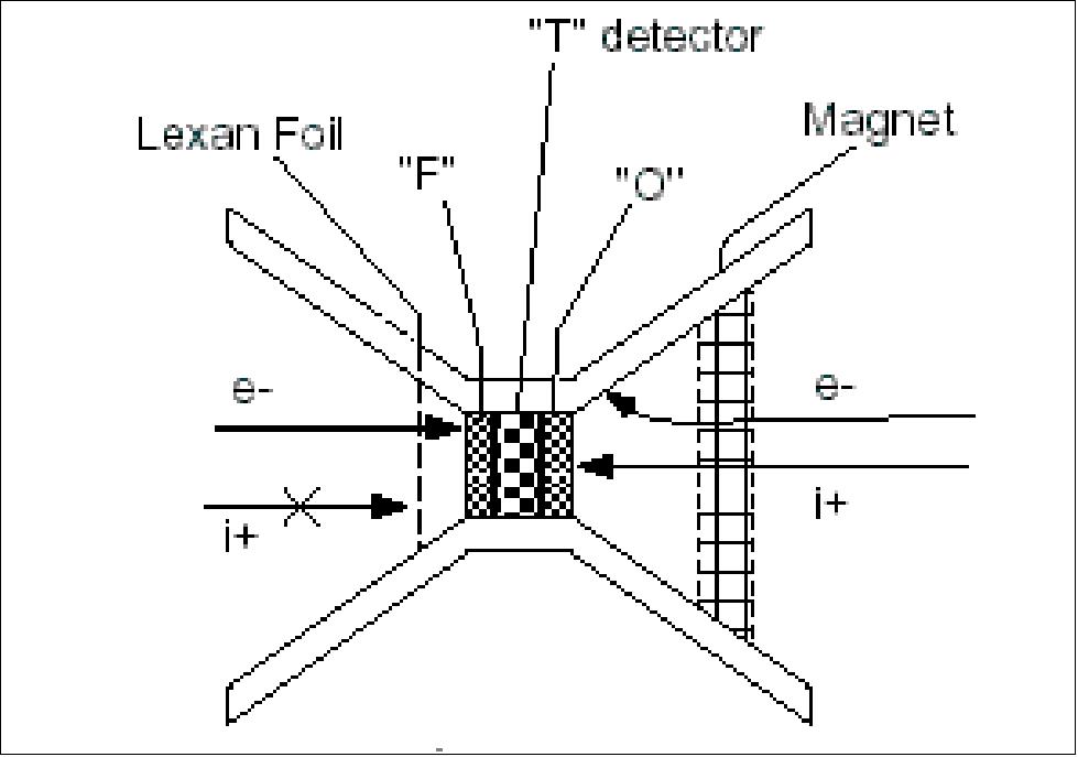
SST calibration: Absolute calibration points are determined by monitoring the highest energy of protons stopped and by placing the pairs (or triplets) of detectors in coincidence and monitoring the minimum ionizing energy for penetrating particles.
SCM (Search Coil Magnetometer)
SCM was built by CNRS/CETP (Centre d'etude des Environnements Terrestre et Planetaire) of Velizy/ Saint-Maur, France. SCM is mounted on a 1 m deployable boom. The instrument has a flight heritage on GEOS 1&2, Galileo, Ulysses, Cassini, Freja and Cluster. SCM is identical to the one flown on the CLUSTER/STAFF instrument, while its electronics are a simplification of the ones flown on the FAST IDPU (Instrument Data Processing Unit).
SCM measures the variation of the magnetic flux threading three orthogonal high permeability m-metal rods. The unit sensitivity is 0.5 pT (Hz)1/2 @ 10 Hz. A flux feedback loop is employed to ensure phase stability. The triaxial sensor is mounted on a single-hinge, 1m graphite epoxy boom. The signals from the three sensors are pre-amplified and then processed together with EFI data at the IDPU. The IDPU consists of one analog and one digital board. The analog board serves primarily the B- and E-fields processing and includes the SCM pre-amplifiers. The analog signal is pre-amplified and then filtered (together with the E-fields signals) and processed for routine waveform (DC 32 samples/s) and for burst waveform (128Hz-8kHz) production. The DSP (Digital Signal Processor) takes 2n continuous segments (n=0...7, commandable) of 1024 data points and performs FFTs of the data and subsequent averaging in frequency. Consecutive spectral averaging reduces noise further. 74)
SCM calibration: Absolute amplitude and phase calibration takes place with calibration coils that create a known AC pseudo-random noise consisting of a series of discrete frequencies covering most of the bandwidth (10 Hz-8 kHz).
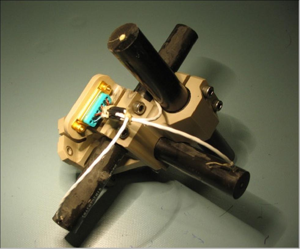
EFI (Electric Field Instrument)
The experiment is built by UCB to the heritage of S3-3, ISEE-1, CRRES, POLAR and CLUSTER. The 3D EFI experiment consists of 4 spin-plane spherical sensors each on a 20 m deployable cable and 2 axial tubular sensors, each 1m-long and mounted on a 4 m long stacer element. The sensors (8 cm in diameter) are identical to the ones delivered for flight on the CLUSTER-II satellites. The axial, two-stage stacer elements are identical to ones used on POLAR, FAST and rockets. The 1 m long, 2 mm diameter, stowable tubular sensor is of the standard STEM line built by commercial outfits (Orbital/TRW/AEC-ABLE). The sensor electronics are simplified versions of the CLUSTER design. 75)

The primary science requirements are derived from the need to determine at the times of onset at 8-10 RE: 1) The plasma pure convective motion, i.e., without the effects of diamagnetic drifts that ESA measurements are subject to. 2) The low frequency (T~1min) wave mode and pointing flux.
EFI specifications: The preamplifier electronics for the wire sensors are housed inside a hockeypuck arrangement, which also acts as a stub for the wires. The deployment mechanism is identical to CLUSTER's but packaging is analogous to FAST due to the reduced volume requirements of the THEMIS EFI experiment. The boom electronics, located at the EFI housing, perform stub and guard voltage control and sphere-biasing. Signal processing takes place in the IDPU, together with the SCM. Routine waveforms (at 32 samples/s) or burst waveforms (at 128 - 8192 samples/s) are captured and processed just as for the SCM data. Spectral processing of the low frequency (< 8 kHz) data occurs in the DSP in a fashion identical to the SCM.
EFI calibration: The individual Probe calibration results in absolute DC measurement accuracy of 0.1 mV/m, i.e., <10% of the field value anticipated during fast flows. Increased confidence in the measurements is being obtained from inter-spacecraft calibration at quiet times.
Instrument | Mass (kg) | Power (W) | Recent Flight | Institute |
FGM @ sensor | 0.1 |
| Equator-S | TUBS |
FGM boom | 1.2 | Fast, Lunar Prospector | UCB | |
FGM @ DPU | 0.3 | 0.8 | MIR | IWF |
ESA @ sensor | 2.1 | 1.9 | FAST | UCB |
ESA @ DPU | 0.3 | 0.6 | FAST | UCB |
SST @ sensor | 1.3 | 0.9 | WIND | UCB, ESTEC |
SST @ DPU | 0.1 | 0.2 | WIND | UCB |
SCM @ sensor | 0.7 |
| CLUSTER | CETP |
SCM boom | 0.5 |
| Lunar Prospector | UCB |
SCM pre-amps | 0.3 | 0.1 | CLUSTER | CETP |
EFI (4) spin plane | 7.2 | 0.3 | CLUSTER | UCB |
EFI (2) axials | 4.1 | 0.2 | POLAR | UCB |
EFI/SCM @ DPU | 1.7 | 2.8 | FAST | UCB |
DPU process, compress & store | 1.2 | 4.5 | FAST. Lunar Prospector | UCB |
Total | 21.0 | 12.1 |
|
|
Maximum expected | 23.6 | 14.8 |
|
|
Average reserve | 13% | 22% |
|
|
Ground Segment
THEMIS uses multiple ground stations to communicate with the five probes and to recover telemetry data. In addition, special real-time operations such as the post-launch probe separation event and near-perigee orbit maneuvers are supported by NASA's TDRSS (Tracking and Data Relay Satellite System). Orbit determination is based on Doppler tracking, and attitude determination on sun sensor and three-axis magnetometer data. 76) 77)
The THEMIS constellation is operated in store-and-forward mode. Science and engineering data are recorded in onboard solid-state memory and are recovered primarily near perigee at the highest data rate compatible with the predicted link margin for any given pass. The required, uncompressed science data volume is 750 Mbit per orbit for each probe. Prior to transmission to the ground, science data are compressed, typically along the inbound leg of the orbits. Instrument configuration for science data acquisition is based on predicted crossing times of magnetospheric regions of interest in combination with various on-board trigger algorithms.
Use of the UCB ground station and USN stations. All aspects of THEMIS constellation operations are performed at the MOC (Mission Operations Center) at UCB/SSL and include mission and science operations, flight dynamics and ground station operations. Virtually all state-of-health monitoring and tracking passes are conducted in lights-out mode, while passes involving commanding or special operations are supported by flight controllers at the console.
NASA's GN (Ground Network) and Space Network (SN) support special real-time operations such as launch and near-perigee orbit maneuvers. All THEMIS command and control, as well as mission planning functions are performed at the MOC. Data are transferred between individual ground systems elements via secure network segments, such as NASA's Internet Protocol Operational Network (IONet). The Open Internet is used for post-pass transfer of telemetry files, and also for transfer of acquisition and tracking data with some of the ground stations.
Probe bus identifiers | Mission orbital slot identifiers | Orbital period |
THEMIS-B | THEMIS-P1 | 4-day orbit |
THEMIS-C | THEMIS-P2 | 2-day orbit |
THEMIS-D | THEMIS-P3 | 1-day orbit |
THEMIS-E | THEMIS-P4 | 1-day orbit |
THEMIS-A | THEMIS-P5 | 4/5 day orbit |
The probe placement decision concerned the assignment of probe bus identifiers THEMIS A-E to mission orbit slots P1-P5. While the latter designators were assigned primarily for mission design and science data analysis, all MOC functions continued to use the probe bus identifiers assigned prior to launch for all aspects of operations. This approach had the advantage that no reconfiguration of the MOC was required as a result of the orbit slot assignment.
The THEMIS ground and flight systems were designed and implemented to support both autonomous and automated functions with the goal to increase reliability and to reduce risk and operations costs.
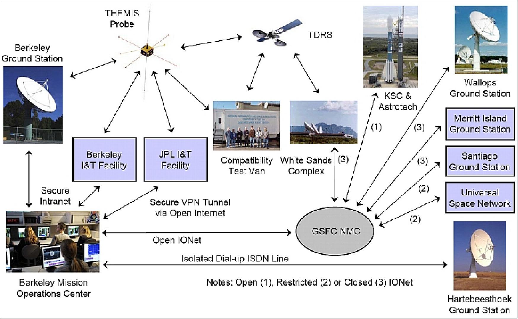
Obtaining sufficient measurements from the instrument subsystems requires that each THEMIS probe collect and store approximately 100-140 MB of data per orbit, which translates to an average rate of between 270-1500 byte/s, depending on the orbit period. The S-band communications system allows downlink of these data at the highest two (524.288 and 1048.576 kbit/s) of ten available telemetry data rates near perigee, using a worldwide network of 11 m class ground stations, including the BGS (Berkeley Ground Station) located at UCB/SSL. To ensure the probes are never completely out of contact, the telemetry link can still be closed at 4 kbit/s through these same 11 m class ground stations at the maximum apogee distance of 200,000 km.
Range rate measurements from multiple ground stations allow maintaining accurate orbit models for all five probes. Two-way Doppler tracking is achieved at all ranges and is conducted concurrently with both scheduled data playback and state of health monitoring pass supports.
Ground system extension for ARTEMIS:
During the Earth-Moon transfer phase, the probes will travel as far as 1.6 million km away from Earth – over seven times farther than the highest apogees of the prime mission phase. Once in the lunar orbit, the probes will be approximately 400,000 km from Earth. Recovering stored scientific measurements collected at a frequency commensurate with the prime mission from lunar distances can only be accomplished by utilizing much larger, more efficient ground antennas. Therefore, the project undertook the development effort to add seven DSN Deep Space Network) 34 m antennas (stations 15, 24, 27, 34, 45, 54 and 65) to the existing spectrum of ground stations already supporting the THEMIS mission. his effort required integrating new telemetry and telecommand interfaces, supporting new tracking and ranging data formats, and adopting new scheduling interfaces into the existing mission operations framework.. 78)
The SGS (SatTrack Gateway Server) orchestrates the processes of pass and event scheduling, flight dynamics product generation, ground station automation, telemetry and command flow management, and command and control system operation. A crucial component of the SatTrack Suite is FrameRouter, which acts as the network equivalent of a matrix switch, providing TCP/IP (Transmission Control Protocol/Internet Protocol) socket-based telemetry and telecommand data flows between remote ground stations and the active command and control software. This scheme, shown in Figure 59 for a pass support with the BGS 11 m antenna, greatly simplifies operations in a multi-ground station, multi-satellite environment, as all ground stations see a consistent virtual interface to the Berkeley MOC.
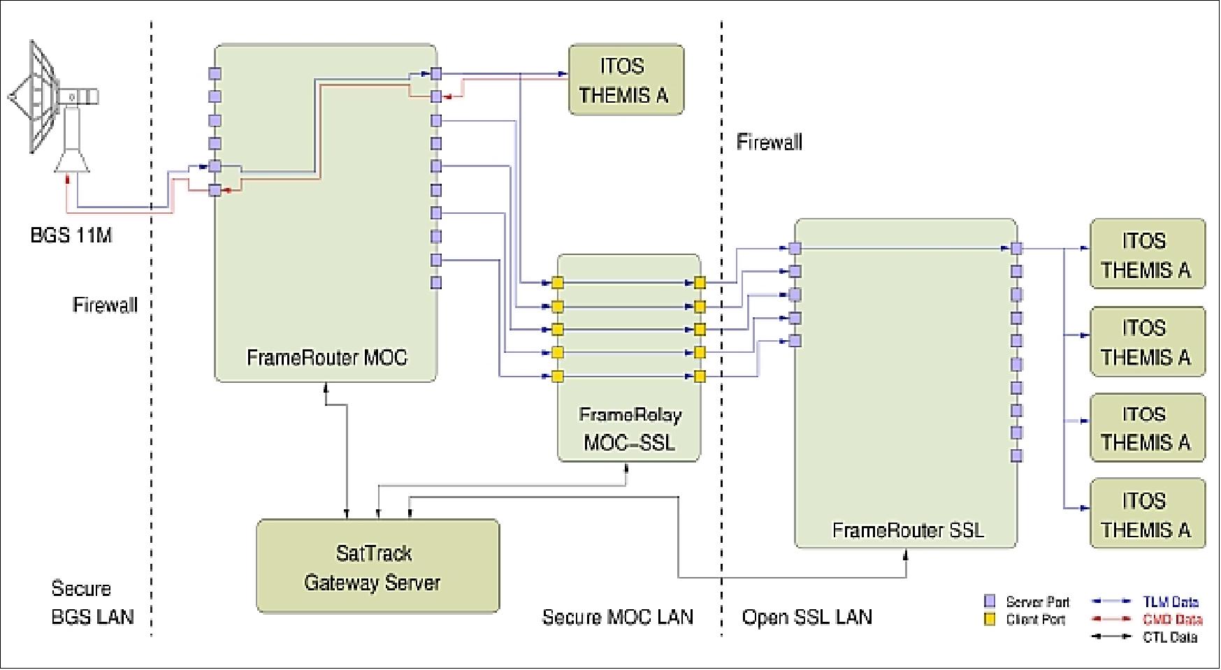
Legend of Figure 59: The example shown for THEMIS A real-time telemetry and telecommand data flows between the BGS (Berkeley Ground Station) and the primary ITOS (Integrated Test and Operations System) command and control workstation. Telemetry data are also routed to additional ITOS workstations to allow remote monitoring of spacecraft state-of-health for special operations.
The interface between the MOC and the DSN ground stations is facilitated by the SLE (Space Link Extension), a CCSDS recommended standard which extends existing CCSDS telemetry and telecommand space link protocols with a cross-support service model that governs data transport and management.
In contrast to the unidirectional data flows that are commonly used for THEMIS with GN and SN, SLE telemetry and telecommand service providers and users communicate as peers connected by bidirectional TCP/IP sockets, constantly exchanging data, management, and heartbeat messages. The SLE recommendation presently provides service models for transporting all telemetry transfer frames on the master channel RAF (Return All Frames), or frames from a single virtual channel RCF (Return Channel Frame) from a ground station to the MOC, and for transporting forward CLTUs (FCLTU - Forward Command Link Transmission Units) from the MOC to the ground station.
Ranging: The original THEMIS concept of operations required only two-way Doppler tracking data from all supporting ground stations to be used for orbit determination. However, the project became interested in exploring the existing, but so far untested ranging capabilities in light of the upcoming DSN integration for ARTEMIS.
Ground observations:
Ground observations are being carried out by 20 Ground Based Observatories (GBO), spread across Alaska and Canada. Each GBO uses an ASI (All-Sky Imager) camera and a GMAG (Ground Magnetometer) to monitor the auroral light and ionospheric currents in order to localize the time, location, and evolution of the auroral manifestation of the substorm. A second ground network will include 10 Education and Public Outreach (E/PO) GMAGs located in schools at sub-auroral latitudes in the US.
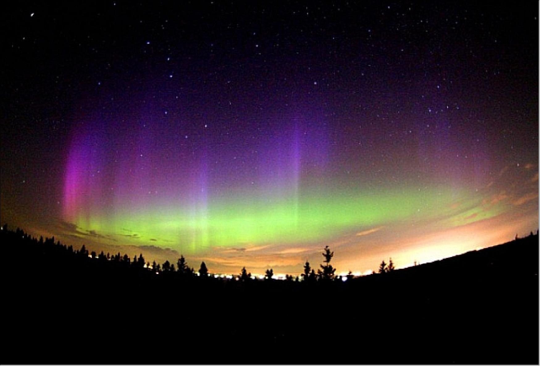
ARTEMIS (Acceleration Reconnection Turbulence, and Electrodynamics of Moon Interaction with the Sun)
ARTEMIS represents an ambitious THEMIS mission extension involving the transfer of the outer two spacecraft (P1 and P2) from Earth orbits to lunar orbits where they will conduct measurements of the Moon’s interaction with the solar wind and its crustal magnetic fields. Earth departure of these two spacecraft is accomplished by successively raising the apogees of their orbits until lunar perturbations become the dominant forces significantly altering their trajectories. This orbit raise sequence requires over forty maneuvering events, with multiple lunar approaches and fly-bys, before setting the two spacecraft on low-energy transfer trajectories to lunar orbit in February and March 2010. 79)
The goal is to maneuver the two spacecraft into the Earth-Moon Lagrangian points and eventually into lunar orbit - to observe the same phenomena as before but from a different perspective.
ARTEMIS orbit raise maneuver sequence:
At the beginning of the ARTEMIS Earth-Orbit Phase, P1 occupied the largest of the THEMIS orbits with a period of 4-days, a perigee of 1,936 km, and an apogee of 195,703 km. P2 held the second largest orbit with a period of 2-days, a perigee of 3,201 km, and an apogee of 117,438 km. Figure 3 illustrates the general configuration of these orbits. The spacecraft spin-axis orientations at this time were approximately 8º from an ecliptic south attitude and with a spin period of approximately 3 seconds.
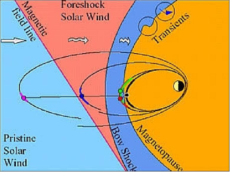
Legend to Figure 61: ARTEMIS-P1 is colored magenta and P2 is blue. The red, green and black are the other three THEMIS spacecraft.
The Earth-Orbit Phase of the ARTEMIS trajectory had two goals to accomplish; raise the apogee of both spacecraft through a series of ORMs (Orbit Raise Maneuvers) to near lunar altitudes and to target the lunar gravity assists needed to transition into the Trans-Lunar trajectories through a series of FTMs (Flyby Targeting Maneuvers). Both ORM and FTM events are designated serially from 1 (ORM1, ORM2, etc).
The goal of the ORMs is to increase the altitude of apogee and the orbital period. The ORM sequence for both spacecraft can be highly sensitive to phasing with the mission baseline. As ORM maneuvers are executed navigation and performance errors could accumulate in the spacecraft’s phase and prevent proper targeting of the flyby events. Subsequent maneuvers in the sequence would have to be adjusted to remove these errors. This issue is analogous to challenges faced during the operation of the THEMIS mission where five spacecraft were required to maintain proper phasing with ground based observatories located in central Canada.
ARTEMIS-P1’s orbit raise maneuver sequence:
P1’s orbit raise maneuver sequence consisted of five radial thrust ORMs starting on August 1st, 2009. Due to the time of year, P1’s orbital alignment was phased relative to the sun such that the majority of its near perigee trajectory was shadowed by the Earth. The requirement that sun-synchronous maneuvers be performed in full sunlight necessitated that all of P1’s ORM maneuvers be split into two burn events that bracketed these shadows. The split ORMs are designated such that the pre-shadow maneuvers are labeled A and the post shadow maneuvers are labeled B (e.g. ORM1A and ORM1B).
The total P1 ORM sequence used 99.168 m/s of ΔV, which was 2.6% more than predicted in the baseline trajectory due to performance errors.
ARTEMIS-P2 orbit raise maneuver sequence:
The P2 ORM sequence is more extensive, consisting of 27 ORM events, due to the significantly smaller orbital size at the start of the ARTEMIS Earth-Orbit Phase. The spacecraft was also experiencing Earth shadows near perigee, which necessitated the segmenting of ORM3 through ORM14 into pre- and post-shadow maneuvers, increasing the total number of burn events to 39. - The trajectory of P2 from July 21, 2009 through March 1, 2010 is shown in Figure 62.
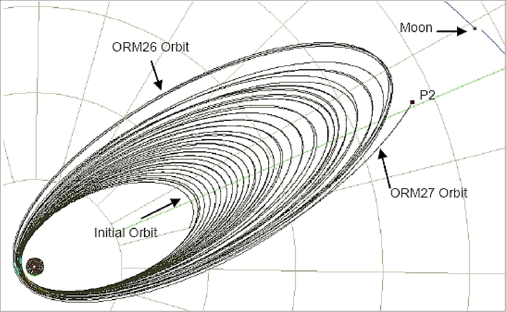
ARTEMIS FTM (Flyby Targeting Maneuver) sequence:
With the completion of the ORM sequence, the two ARTEMIS spacecraft were on course to navigating the lunar flybys that will result in their transfer to the Trans-Lunar phase of the mission. To complete the targeting of these flyby events both spacecraft required a series of FTMs to properly connect the final ORM orbital states to the trans-lunar injections.
- P1 FTM sequence: On December 8, 2009, P1 experienced it first lunar flyby event, passing within 18,576 km of the Moon and receiving a significant inclination change as a result.
- P2 FTM and shadow deflection sequence: P2’s path to the Trans-Lunar transfer trajectory only requires one lunar flyby event. This flyby occurred on March 28, 2010, after the long Earth shadow event on March 22, 2010.
ARTEMIS Trans-Lunar Phase:
The Trans-Lunar Phase started for both ARTEMIS spacecraft upon the conclusion of their lunar flyby events. P1 and P2 will reach maximum ranges of 1.5 million km and 1.2 million km respectively. P1 will execute one deterministic maneuver in deep space and an insertion burn resulting in a LL2 (Lunar Lagrangian point 2) Lissajous orbit on August 23rd, 2010.
P2 will be executing two maneuvers in deep space, along with its insertion burn, which will result in a LL1 (Lunar Lagrangian point 1) Lissajous orbit on October 22, 2010.
The ARTEMIS extension to the THEMIS mission is a very ambitious endeavor that is expected to return a high scientific yield from the study of the Moon and it nearby environment. The planned layovers in LL1 and LL2 Lissajous orbits will be of further interest to the space exploration communities and the challenges faced in the implementation of their station-keeping19 will be the subject of future publications.
The implementation of the ARTEMIS trajectory has been on schedule. The P1 and P2 spacecraft are now well into their Trans-Lunar trajectories. Both spacecraft will be arriving in their respective Lissajous orbits in August and October, 2010 respectively.
ARTEMIS-P1 First Earth-Moon Libration Orbiter:
In August 2010, ARTEMIS-P1 became the first spacecraft to navigate to and perform stationkeeping operations around the Earth-Moon L1 and L2 Lagrangian points (also referred to as LL1 and LL2, respectively). There are five Lagrangian points associated with the Earth-Moon system. The two points nearest the moon are of great interest for lunar exploration. These points are called L1 (located between the Earth and Moon) and L2 (located on the far side of the Moon from Earth), each about 61,300 km above the lunar surface. It takes about 14 to 15 days to complete one revolution about either the L1 or L2 point. These distinctive kidney-shaped orbits are dynamically unstable and require weekly monitoring from ground personnel. Orbit corrections to maintain stability are regularly performed using onboard thrusters (Ref. 60). 80) 81)
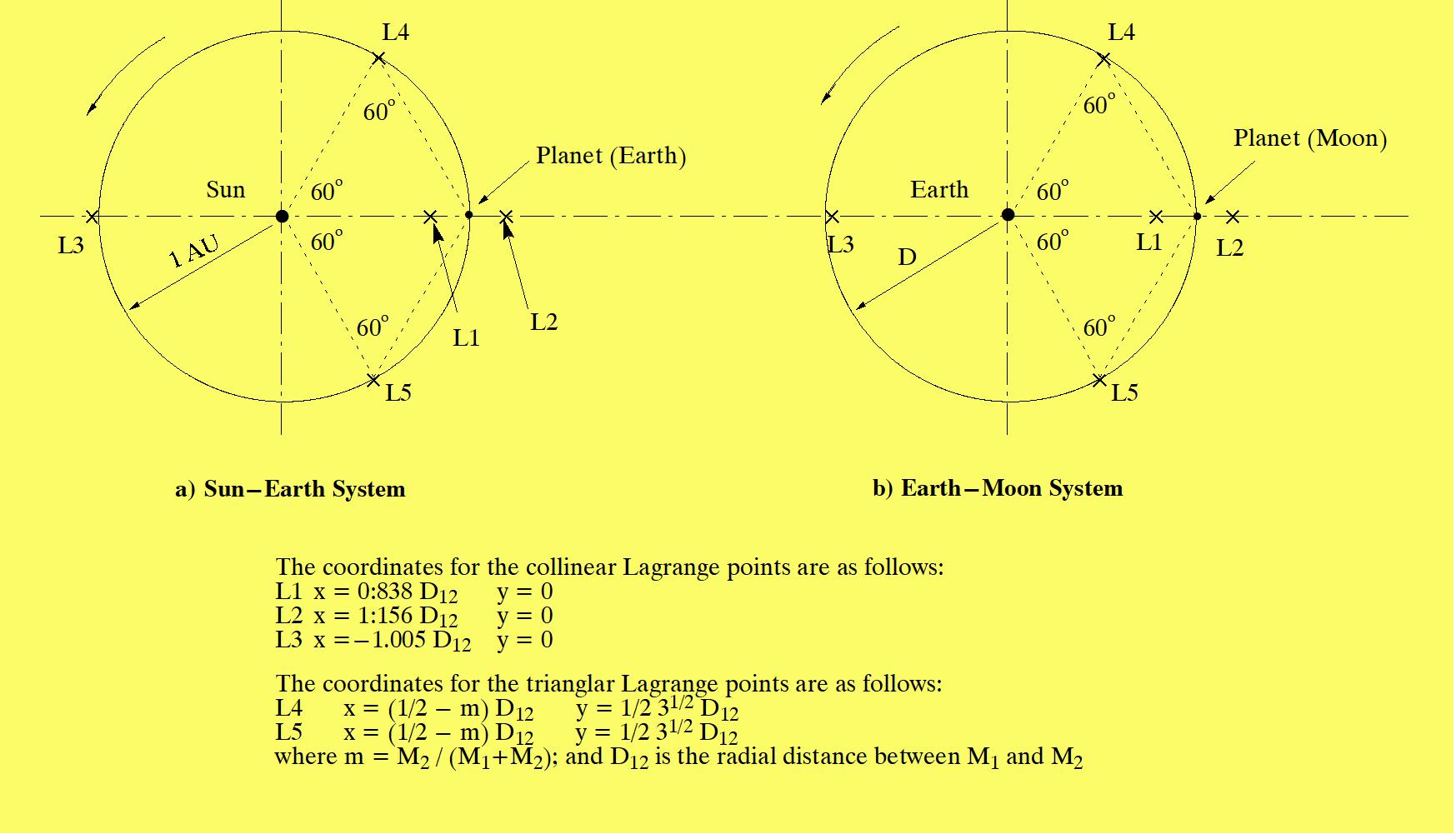
After the ARTEMIS-P1 spacecraft has completed its first four revolutions in the L2 orbit, the ARTEMIS-P2 spacecraft will enter the L1 orbit. The two sister spacecraft will take magnetospheric observations from opposite sides of the moon for three months, then ARTEMIS-P1 will move to the L1 side where they will both remain in orbit for an additional three months. Flying the two spacecraft on opposite sides, then the same side, of the moon provides for collection of new science data in the Sun-Earth-Moon environment.
ARTEMIS will use simultaneous measurements of particles and electric and magnetic fields from two locations to provide the first three-dimensional perspective of how energetic particle acceleration occurs near the Moon's orbit, in the distant magnetosphere, and in the solar wind. ARTEMIS will also collect unprecedented observations of the space environment behind the dark side of the Moon – the greatest known vacuum in the solar system – by the solar wind.
In late March 2011, both spacecraft will be maneuvered into elliptical lunar orbits where they will continue to observe magnetospheric dynamics, solar wind and the space environment over the course of several years.
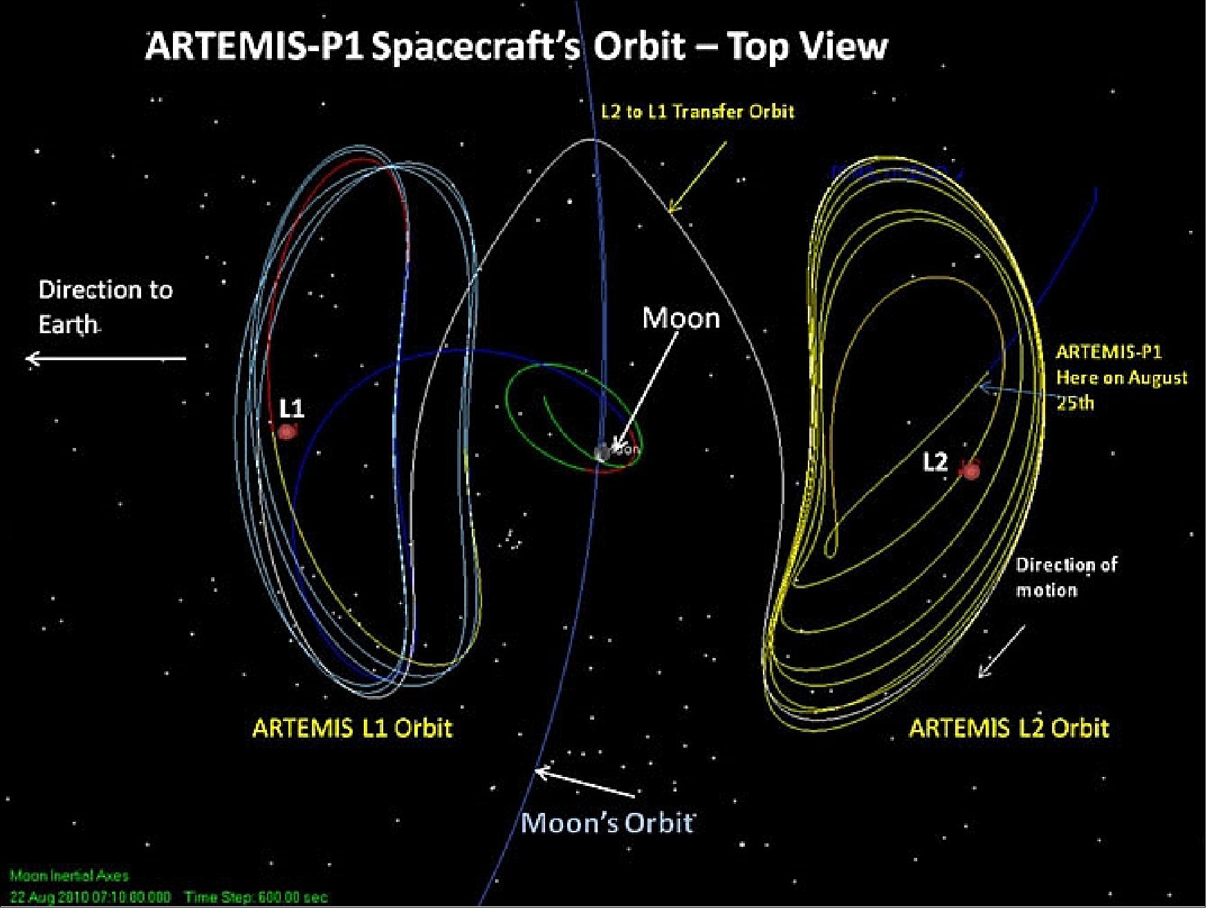
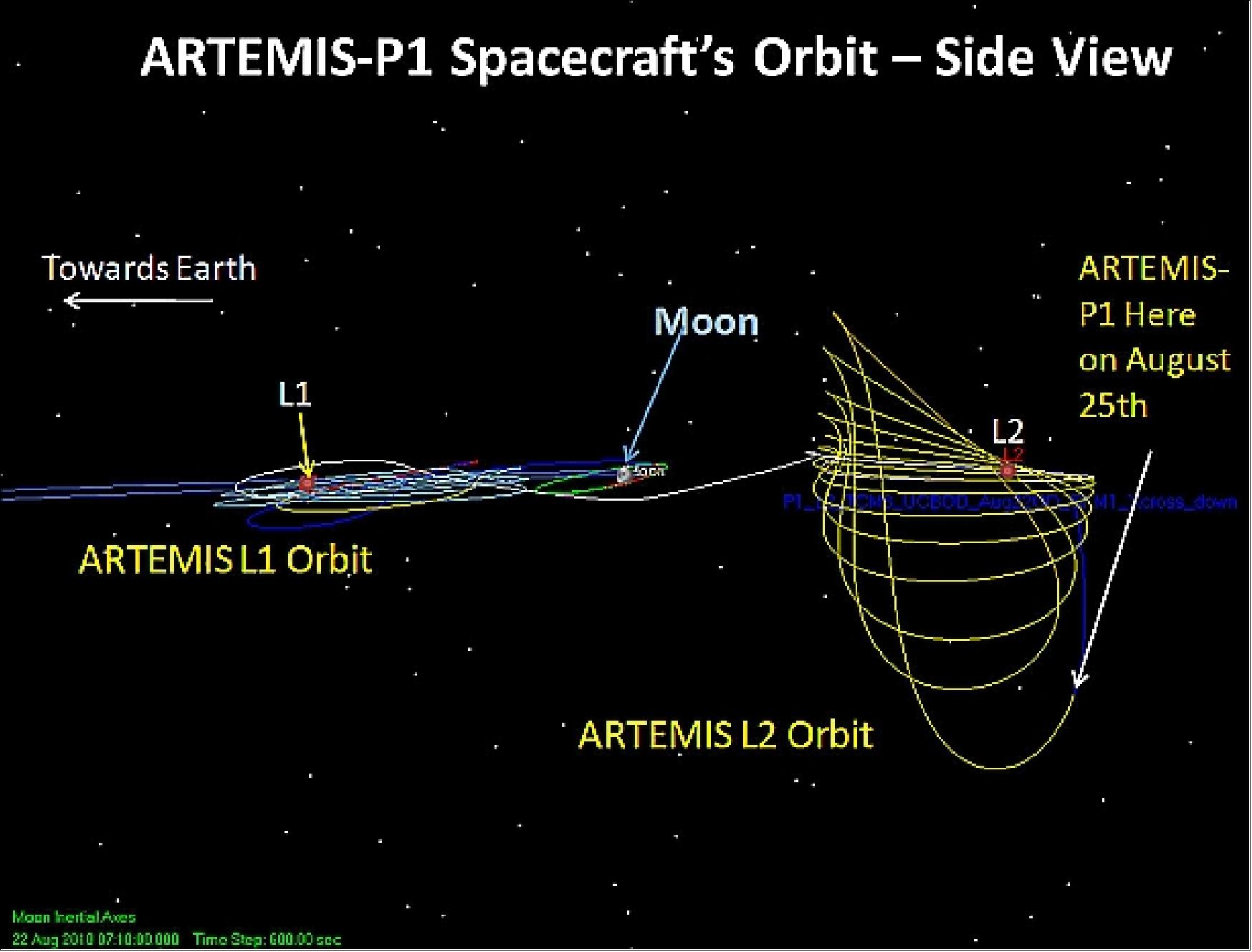
Other benefits of this first ever libration orbit mission include the investigation of lunar regions to provide a staging location for both assembly of telescopes or human exploration of planets and asteroids or even to serve as a communication relay location for a future lunar outpost. The navigation and control of the spacecraft will also provide NASA engineers with important information on propellant usage, requirements on ground station resources, and the sensitivity of controlling these unique orbits (Ref. 80).
References
1) http://themis.ssl.berkeley.edu/index.shtml
2) Information provided by Vassilis Angelopoulos of UCB/SSL and by Thomas Ajluni of Swales Aerospace
3) V. Angelopoulos, “THEMIS in Relation to CLUSTER and Double Star,” Proceedings Cluster and Double Star Symposium - 5th Anniversary of Cluster in Space, Noordwijk, The Netherlands, 19 - 23 Sept. 19-23, 2005 (ESA SP-598, January 2006), http://sci.esa.int/science-e/www/object/doc.cfm?fobjectid=39621
4) W. R. Eppler, “An Optimized Small Satellite Bus and Structure for the THEMIS mission,” Proceedings of the 20th Annual AIAA/USU Conference on Small Satellites, Logan, UT, Aug. 14-17, 2006, paper: SSC06-IV-5
5) T. Ajluni, “SmallSat Lessons Learned on THEMIS: Approaches to Standard Interfaces That Succeeded or Failed,” Proceedings of the 19th AIAA/USU Conference on Small Satellites, Logan, UT, USA, Aug. 8-11, 2005, SSC05-V-8
6) http://www.nasa.gov/mission_pages/themis/main/index.html
7) THEMIS Project Data Management Plan, July 15, 2004, URL:http://nssdc.gsfc.nasa.gov/archive/pdmp/THEMIS_PDMP_draft_20041018.doc
8) M. J. Cully, W. Chen, K. Brenneman, G. T. Delory, “Application of the THEMIS Bus to New Missions,” Proceedings of the 21st Annual AIAA/USU Conference on Small Satellites, Logan, UT, USA, Aug. 13-16, 2007, SSC07-II-5
9) B. Kraeuter, G. Shiblie, “Probe Bus Avionics Unit Development and Validation,” Proceedings of the 21st Annual AIAA/USU Conference on Small Satellites, Logan, UT, USA, Aug. 13-16, 2007, SSC07-XIII-5
10) Debra Werner, “A 50-Year History of Training the Next Generation of Space Scientists,” Space News, Sept. 21, 2009, p. 16
11) “THEMIS Overview and Goals,” UCB, URL: http://themis.ssl.berkeley.edu/overview.shtml
12) S. Frey, V. Angelopoulos, M. Bester, H. Frey, “THEMIS Orbit Updates Prior to Second Tail Season 2008/2009,” 1st Joint CLUSTER-THEMIS Workshop, UNH (University of New Hampshire), Sept. 23-26, 2008, URL: http://www.spaceplasma.unh.edu/wiki/images/d/d3/Frey_THEMIS_orbit_updates_SW_092408.pdf
13) http://themis.ssl.berkeley.edu/orbits.shtml
14) Lina Tran, ”With NASA Data, Researchers Find Standing Waves at Edge of Earth’s Magnetic Bubble,” NASA Feature, 6 October 2021, URL: https://www.nasa.gov/feature/goddard/2021/
themis-researchers-find-standing-waves-at-edge-of-earth-magnetic-bubble
15) M. O. Archer, M. D. Hartinger, F. Plaschke, D. J. Southwood & L. Rastaetter ,”Magnetopause ripples going against the flow form azimuthally stationary surface waves,” Nature Communications, Vol. 12, Article Number 5697, Published: 06 October 2021, https://doi.org/10.1038/s41467-021-25923-7
16) Mara Johnson-Groh, Rob Garner, ”Aurora Mysteries Unlocked With NASA’s THEMIS Mission,” NASA Feature, 14 August 2020, URL: https://www.nasa.gov/feature
/aurora-mysteries-unlocked-with-nasa-s-themis-mission/
17) K. A. Sorathia, V. G. Merkin, E. V. Panov, B. Zhang, J. G. Lyon, J. Garretson, A. Y. Ukhorskiy, S. Ohtani, M. Sitnov, M. Wiltberger, ”Ballooning‐Interchange Instability in the Near‐Earth Plasma Sheet and Auroral Beads: Global Magnetospheric Modeling at the Limit of the MHD Approximation,” Geophysical Research Letters, Volume47, Issue14, 28 July 2020, e2020GL088227, Published: 15 June 2020, https://doi.org/10.1029/2020GL088227, URL: https://agupubs.onlinelibrary.wiley.com/doi/epdf/10.1029/2020GL088227
18) Evgeny V. Panov, San Lu, Philip L. Pritchett, ”Understanding Spacecraft Trajectories Through Detached Magnetotail Interchange Heads,” Volume 125, Issue 5, Published: 03 May 2020, https://doi.org/10.1029/2020JA027930
19) Mara Johnson-Groh, Rob Garner, ”In Solar System’s Symphony, Earth’s Magnetic Field Drops the Beat,” NASA News, 12 February 2019, URL: https://www.nasa.gov/feature/
goddard/2019/in-solar-system-s-symphony-earth-s-magnetic-field-drops-the-beat
20) M.O. Archer, H. Hietala, M. D. Hartinger, F. Plaschke & V. Angelopoulos, ”Direct observations of a surface eigenmode of the dayside magnetopause,” Nature Communications, Vol. 10, Article No 615, Published: 12 February 2019, https://doi.org/10.1038/s41467-018-08134-5 , URL: https://www.nature.com/articles/s41467-018-08134-5.pdf
21) Mara Johnson-Groh, Rob Garner, ”Pulsating Aurora Mysteries Uncovered with Help from NASA’s THEMIS Mission,” NASA, 20 Feb. 2018, URL: https://www.nasa.gov/feature/goddard
/2018/pulsating-aurora-mysteries-uncovered-with-help-from-nasa-s-themis-mission
22) S. Kasahara, Y. Miyoshi, S. Yokota, T. Mitani, Y. Kasahara, S. Matsuda, A. Kumamoto, A. Matsuoka, Y. Kazama, H. U. Frey, V. Angelopoulos, S. Kurita, K. Keika, K. Seki , I. Shinohara, ”Pulsating aurora from electron scattering by chorus waves,” Nature, Vol. 554, pp: 337–340, 15 February 2018, doi:10.1038/nature25505, URL of abstract: https://www.nature.com/articles/nature25505
23) ”Cluster measures turbulence in Earth's magnetic environment,” ESA, 29 January. 2018, URL: http://sci.esa.int/cluster/59947-cluster-measures-turbulence-in-earth-s-magnetic-environment/
24) L. Z. Hadid, F. Sahraoui, S. Galtier, S. Y. Huang, ”Compressible Magnetohydrodynamic Turbulence in the Earth’s Magnetosheath: Estimation of the Energy Cascade Rate Using in situ Spacecraft Data,” Physical Review Letters, Vol. 120, Issue 5, 2 Feb. 2018, URL of abstract: https://journals.aps.org/prl/abstract/10.1103/PhysRevLett.120.055102
25) Mara Johnson-Groh, ”Studying Magnetic Space Explosions with NASA Missions,” NASA, March 9, 2017, URL: https://www.nasa.gov/feature/
goddard/2017/studying-magnetic-space-explosions-with-nasa-missions
26) H. Hietala, A. V. Artemyev, V. Angelopoulos, ”Ion dynamics in magnetotail reconnection in the presence of density asymmetry,” Journal of Geophysical Research: Space Physics, Volume 122, Issue 2, February 28, 2017, pp: 2010–2023, DOI: 10.1002/2016JA023651, URL of abstract: http://onlinelibrary.wiley.com/doi/10.1002/2016JA023651/full
27) Mara Johnson-Groh, ”10 Years Strong with NASA's THEMIS Mission,” NASA, Feb. 21, 2017, URL: https://www.nasa.gov/feature/10-years-strong-with-nasas-themis-mission
28) ”THEMIS News,” UCLA, Nov. 14, 2016, URL: http://themis.igpp.ucla.edu/news.shtml
29) L. B. Wilson, III, D. G. Sibeck, D. L. Turner, A. Osmane, D. Caprioli, V. Angelopoulos, ”Relativistic Electrons Produced by Foreshock Disturbances Observed Upstream of Earth’s Bow Shock,” Physical Review Letters, Vol. 117, 215101 (2016), published on Nov. 14, 2016, doi:10.1103/PhysRevLett.117.215101, URL of abstract: https://journals.aps.org/prl/issues/117/21
30) S. Frey, V. Angelopoulos, M. Bester, ”The Revised Concept of the THEMIS and MMS Coordination,” Proceedings of the 25th International Symposium on Space Flight Dynamics, Munich, Germany, Oct. 19-23, 2015, URL: http://issfd.org/2015/files/downloads/papers/011_Frey.pdf
31) “NASA Response to the 2015 Senior Review for Heliophysics Operating Missions,” NASA, July 10, 2015, URL: http://science.nasa.gov/media/medialibrary/
2015/07/10/NASAResponse2015SeniorReview_FINAL.pdf
32) “The 2015 Senior Review of the Heliophysics Operating Missions, NASA, June 11, 2015, URL: http://science.nasa.gov/media/medialibrary/2015/07/10/HeliophysicsSeniorReview2015_FINAL.pdf
33) “ARTEMIS,” NASA SSERVI (Solar System Exploration Research Virtual Institute), 2015, URL: http://sservi.nasa.gov/articles/artemis/
34) J. Wendel, “ARTEMIS News,” SSL Berkeley, January 15, 2015, URL: http://artemis.ssl.berkeley.edu/news.shtml
35) H. Zhang, K. K. Khurana, M. G. Kivelson, V. Angelopoulos, W. X. Wan, L. B. Liu, Q.-G. Zong, Z. Y. Pu, Q. Q. Shi, W. L. Liu (2014), “Three-dimensional lunar wake reconstructed from ARTEMIS data,” Journal of Geophysical. Research, Space Physics, Vol. 119, Issue 7, July 2014, pp: 5220–5243, doi:10.1002/2014JA020111
36) Karen C. Fox, “NASA's THEMIS Discovers New Process that Protects Earth from Space Weather ,” NASA, March 6, 2014, URL: http://www.nasa.gov/content/goddard/
themis-discovers-new-process-that-protects-earth-from-space-weather/#.Uxns9c7ihqO
37) B. M. Walsh, J. C. Foster, P. J. Erickson, D. G. Sibeck, “Simultaneous Ground- and Space-Based Observations of the Plasmaspheric Plume and Reconnection,” Science, March 7, 2014, Vol. 343, No 6175, pp: 1122-1125, DOI: 10.1126/science.1247212, URL of abstract: https://www.sciencemag.org/content/343/6175/1122
38) Information provided by Vassilis Angelopoulos (Mission PI) of UCLA and UCB.
39) “UCLA Experimental Space Physics — THEMIS-MMS Conjunctions: A Step Closer to Reality,” Nov. 8, 2013, URL: http://esp.igpp.ucla.edu/news.html
40) Vassilis Angelopoulos, A. Runov, X.-Z. Zhou, D. L. Turner, S. A. Kiehas, S.-S. Li, I. Shinohara, “Electromagnetic Energy Conversion at Reconnection Fronts,” Science, Vol. 341, No 6153, Sept. 27, 2013, pp. 1478-1482, DOI: 10.1126/science.1236992
41) Karen C. Fox, “Several NASA Spacecraft Track Energy Through Space,” NASA, Sept. 26, 2013, URL: http://www.nasa.gov/content/goddard/several-nasa-spacecraft-track-energy-through-space/#.UklL13-JrWI
42) “ARTEMIS News,” Sept. 27, 2013, URL: http://artemis.ssl.berkeley.edu/news.shtml
43) Information provided by Karen C. Fox of NASA/GSFC, Greenbelt, MD, USA.
44) Karen C. Fox, “Six Years in Space for THEMIS: Understanding the Magnetosphere Better Than Ever,” NASA, Feb. 19, 2013, URL: http://www.nasa.gov/mission_pages/themis/news/six-years.html
45) Drew L. Turner, Vassilis Angelopoulos, Yuri Shprits, Pat Cruce, “Storm-time evolution of relativistic electron equatorial phase space density throughout the outer radiation belt,” The paper has been accepted by JGR and will be published in 2013.
46) M. D. Hartinger, D. L. Turner, F. Plaschke, V. Angelopoulos, H. Singer, “The role of transient ion foreshock phenomena in driving Pc5 ULF wave activity,” JGR (Journal of Geophysical Research), Space Physics, Article first published online: 31 JAN 2013, DOI: 10.1029/2012JA018349, URL: http://onlinelibrary.wiley.com/doi/10.1029/2012JA018349/abstract
47) G. I. Korotova, D. G. Sibeck, N. Omidi, V. Angelopoulos, “THEMIS observations of unusual bow shock motion attending a transient magnetospheric event,” JGR (Journal of Geophysical Research), Space Physics, Article first published online: 8 DEC 2012 , DOI: 10.1029/2012JA017510, URL: http://onlinelibrary.wiley.com/doi/10.1029/2012JA017510/abstract
48) Daniel Cosgrove, Sabine Frey, Jeffrey Marchese, Brandon Owens, Manfred Bester, “ARTEMIS Operations from Earth-Moon Libration Orbits to Stable Lunar Orbits,” Proceedings of SpaceOps 2012, The 12th International Conference on Space Operations, Stockholm, Sweden, June 11-15, 2012
49) Karen C. Fox, “THEMIS Celebrates Five Years of Watching Aurora and Space Weather,” Space Daily, Feb. 24, 2012, URL: http://www.spacedaily.com/reports/
THEMIS_Celebrates_Five_Years_of_Watching_Aurora_and_Space_Weather_999.html
50) J. B. Tao, R. E. Ergun, D. L. Newman, J. S. Halekas, L. Andersson, V. Angelopoulos, J. W. Bonnell, J. P. McFadden, C. M. Cully, H.-U. Auster, K.H.Glassmeier, D. E. Larson, W. Baumjohann, M. V. Goldman, “Kinetic instabilities in the lunar wake: ARTEMIS observations,” Journal of Geophysical Research, Vol. 117, 2012, A03106, 10 pp, doi:10.1029/2011JA017364
51) Stephen B. Broschart, Theodore H. Sweetser, Vassilis Angelopoulos, David C. Folta, Mark A. Woodard, “ARTEMIS lunar orbit insertion and science orbit design through 2013,” Proceedings of the AAS/AIAA Astrodynamics Specialist Conference, Girdwood, Alaska, USA, July 31- Aug. 4, 2011, paper: AAS 11-509
52) David Folta, Theodore Sweetser, “ARTEMIS Mission Overview,” Proceedings of the AAS/AIAA Astrodynamics Specialist Conference, Girdwood, Alaska, USA, July 31- Aug. 4, 2011, paper: AAS 11-510
53) David Folta, Mark Woodard, Theodore Sweetser, Stephen B. Broschart, Daniel Cosgrove, “Design and Implementation of the ARTEMIS Lunar Transfer using multi-body dynamics,” Proceedings of the AAS/AIAA Astrodynamics Specialist Conference, Girdwood, Alaska, USA, July 31- Aug. 4, 2011, paper: AAS 11-511
54) Robert Sanders, “Twin ARTEMIS Probes to Study Moon in 3-D,” UC Berkeley News Center, July 13, 2011, URL: http://newscenter.berkeley.edu/2011/07/13/twin-artemis-probes-to-study-moon-in-3-d/
55) “Two NASA Probes Tackle New Mission: Studying the Moon,” NASA, July 19, 2011, URL: http://www.nasa.gov/centers/goddard/news/releases/2011/11-042.html
56) Karen C. Fox, “ARTEMIS Spacecraft Prepare for Lunar Orbit,” NASA, June 23, 2011, URL: http://www.nasa.gov/mission_pages/artemis/news/lunar-orbit.html
57) Robert Sanders, “Out of THEMIS, ARTEMIS: Earth’s loss is moon’s gain,” UCB, October 27, 2010, URL: http://newscenter.berkeley.edu/2010/10/27/artemis_moon_mission/
58) “THEMIS/Artemis,” June 18, 2009, 365 Days of Astronomy, URL: http://365daysofastronomy.org/2009/06/18/june-18th-themisartemis/
59) Mark Woodard, David Folta, Dennis Woodfork, “ARTEMIS: The First Mission to the Lunar Libration Orbits,” URL: http://www.igpp.ucla.edu/public/THEMIS/SCI/Pubs/artemis/artemis_woodward.pdf
60) V. Angelopoulos, “The ARTEMIS Mission,” 2010, URL: http://www.igpp.ucla.edu/public/THEMIS/SCI/Pubs/artemis/The_ARTEMIS_Mission_SSR_accepted.pdf
61) D. C. Folta, T. A. Pavlak, K. C. Howell , M. A. Woodard, D. W. Woodfork, “Stationkeeping of Lissajous Trajectories in the Earth-Moon System with Applications to ARTEMIS,” Proceedings of the AAS/AIAA Space Flight Mechanics Meeting, February 14-17, 2010, San Diego, CC, USA, paper: AAS 10‐113, URL: https://engineering.purdue.edu/people/kathleen.howell.1/
Publications/Conferences/FolPavHowWoodardWoodfork_10.pdf
62) “Road Cleared for ARTEMIS Mission Implementation,” UCB/SSL, Feb. 27, 2009, URL: http://themis.ssl.berkeley.edu/news.shtml
63) Tony Phillips, “Spacequakes Rumble Near Earth,” NASA, July 27, 2010, URL: http://science.nasa.gov/science-news/science-at-nasa/2010/27jul_spacequakes/
64) Michael Carlowicz, “Colliding auroras produce an explosion of light,” NASA, Dec. 17, 2009, URL: http://www.eurekalert.org/pub_releases/2009-12/nsfc-cap121709.php
65) “Colliding Auroras Create Explosions,” Universe Today, Dec. 17, 2009, URL: http://www.universetoday.com/2009/12/17/colliding-auroras-create-explosions/
66) “Colliding Auroras Produce Explosions Of Light,” Space Daily, Dec. 18, 2009, URL: http://www.spacedaily.com/reports/Colliding_Auroras_Produce_Explosions_Of_Light_999.html
67) Warren Chen, Michael J. Cully, “THEMIS Post Launch Spacecraft Bus Systems Performance Validation: Comparison to Systems Design and Analysis Attributes,” Proceedings of the 22nd Annual AIAA/USU Conference on Small Satellites, Logan, UT, USA, Aug. 11-14, 2008, SSC08-II-1
68) Rani Gran, Laura Layton, “Magnetic Tremors Pinpoint Impact Epicenter Of Earthbound Space Storms,” Space Daily, May 2009, URL: http://www.spacedaily.com/reports/
Magnetic_Tremors_Pinpoint_Impact_Epicenter_Of_Earthbound_Space_Storms_999.html
69) “THEMIS Satellites Discover What Triggers Eruptions of the Northern Lights,” NASA, July 24, 2008, URL: http://www.nasa.gov/mission_pages/themis/auroras/themis_power.html
70) http://www.igep.tu-bs.de/forschung/weltraumphysik/projekte/themis/magnhardw_en.html
71) http://sprg.ssl.berkeley.edu/themis/pdf/Mission_Science.pdf
72) http://www.nasa.gov/mission_pages/themis/spacecraft/ESA.html
73) http://www.nasa.gov/mission_pages/themis/spacecraft/SST.html
74) http://www.nasa.gov/mission_pages/themis/spacecraft/SCM.html
75) http://www.nasa.gov/mission_pages/themis/spacecraft/EFI.html
76) M. Bester, M. Lewis, B. Roberts, L. Croton, R. Dumlao, M. Eckert, J. McDonald, D. Pease, C. Smith, J. Thorsness, J. Wheelwright, S. Frey, D. Cosgrove, D. Rummel, M. Ludlam, H. Richard, T. Quinn, J. Loran, R. Boyd, C. Quan, T. Clemons, “Ground Systems and Flight Operations of the THEMIS Constellation Mission,” Proceedings of the 2008 IEEE Aerospace Conference, Big Sky, MT, USA, March 1-8, 2008
77) Manfred Bester, Mark Lewis, Bryce Roberts, Daniel Cosgrove, “Operations Planning and Mission Readiness Testing for the THEMIS Spacecraft Constellation,” Proceedings of the 2010 IEEE Aerospace Conference, Big Sky, MT, USA, March 6-13, 2010
78) Bryce Roberts, Mark Lewis, Jeremy Thorsness, Gregory Picard, Gregory Lemieux, Jeffrey Marchese, Daniel Cosgrove, Gregory Greer, Manfred Bester, “THEMIS Mission Networks Expansion – Adding the Deep Space Network for the ARTEMIS Lunar Mission Phase,” Proceedings of the SpaceOps 2010 Conference, Huntsville, ALA, USA, April 25-30, 2010, paper: AIAA 2010-1934
79) Daniel Cosgrove, Sabine Frey, Jeffrey Marchese, Brandon Owens, Swapan Gandhi, Manfred Bester, David Folta, Mark Woodard, Dennis Woodfork, “Navigating THEMIS to the ARTEMIS Low-Energy Lunar Transfer Trajectory,” Proceedings of the SpaceOps 2010 Conference, Huntsville, ALA, USA, April 25-30, 2010, paper: AIAA 2010-2352
80) David Folta, Mark Woodard, “ARTEMIS - The First Earth-Moon Libration Orbiter,” NASA, Sept. 13, 2010, URL: http://www.nasa.gov/mission_pages/themis/news/artemis-orbit.html
81) David C. Folta, Mark Woodard, Kathleen Howell, Chris Patterson, Wayne Schlei, “Applications of Multi-Body Dynamical Environments: The ARTEMIS Transfer Trajectory Design,” Proceedings of the 61st IAC (International Astronautical Congress), Prague, Czech Republic, Sept. 27-Oct. 1, 2010, IAC-10,C1,9,9,x7461
The information compiled and edited in this article was provided by Herbert J. Kramer from his documentation of: ”Observation of the Earth and Its Environment: Survey of Missions and Sensors” (Springer Verlag) as well as many other sources after the publication of the 4th edition in 2002. - Comments and corrections to this article are always welcome for further updates (eoportal@symbios.space).
Spacecraft Launch Mission Status Sensor Complement Ground Segment ARTEMIS References Back to Top