T2E (Tier-2 Enabler)
Non-EO
DoD (USA)
Quick facts
Overview
| Mission type | Non-EO |
| Agency | DoD (USA) |
T2E (Tier-2 Enabler) Technology Demonstration Mission
T2E is an ORS (Operationally Responsive Space) Office's mission of the US DoD (Department of Defense) with the goal to change the paradigm of space. ORS will use the T2E mission to exercise their basic philosophy, to develop through contextual application, rather than studies or simulation. Central to the T2E mission will be a calculated gamble that the widely accepted MOSA (Modular Open-System Approach) is the right tool to change the paradigm of space and provide the DoD, as well as their civil, commercial, and international partners, a modular, scalable, and rapidly configurable architecture that can be employed to provide assured space power to the warfighter. 1) 2)
The ORS Office believes that it is most effective to develop the components of their “Reconnaissance Wing for Space” via an end-to-end mission that will graduate with an actual ORS Tier-2 (~ 7-day) response to a relevant COCOM’s (Combatant Command) operational need. T2E is that mission, so the approach must necessarily utilize/demonstrate steps towards this vision.
The T2E mission is internally driven within ORS to mature the processes, capabilities and technologies, i.e., the Enablers, which will allow the ORS Office to reach its End-State Vision. This mission will, for the first time, demonstrate a sustainable end-to-end (mission planning → bus/payload/ground system/LV AI&T → Ops Team training → launch campaign → on-orbit checkout, calibration, hand-off) response capability on a Tier-2 timeline. The payload for the T2E mission is a SAR (Synthetic Aperture Radar) imager providing regional capability.
In priority order, the goals of the T2E mission are:
1) Demonstrate an end-to-end RRSW (Rapid Response Spaceworks) Tier-2 response
2) Develop a standards based, modular, rapidly configurable, multi-mission bus architecture
3) Develop an operationally relevant radar capability
4) Develop a rapidly configurable, multi-mission RF payload architecture.
TE2 Contract Allocations and Implementation Timeframe
The T2E mission goals are tied directly to Task Orders (TOs) on the RRSW and MSV (Modular Space Vehicle) contracts. NGAS (Northrop Grumman Aerospace Systems), as the prime for the MSV bus, will develop the spacecraft (item 2 of objectives).
SNC (Sierra Nevada Corporation), as the prime for the MSV payload, will develop the system described in objectives 3 and 4.
MEI (Millennium Engineering and Integration) as the prime for the RRSW T2E, will integrate the T2E bus to the T2E payload, perform system level “first article” testing, disassemble the articles into a storable state, and execute an end-to-end Tier-2 response triggered by a notional time-critical JFC (Joint Forces Command) need, in accordance with objective 1.
On the programmatic side, the MSV bus and payloads are currently scheduled to arrive at the RRSW for integration in May 2013. The RRSW will spend six months performing system AI&T (Assembly, Integration, and Test) and exercising their personnel, facilities, and hardware in performing a Tier-2 response - prior to executing their “Graduation Exercise” described in mission objective 1.
NASA/ARC (Ames Research Center) in Mountain View, CA is executing all contracts, through a close partnership between ORS and ARC. Just as responsive low cost satellites will allow the ORS Office to develop the capability to augment or replace space capabilities on very short timescales, it will also provide NASA the flexibility to meet science needs and build upon recent discoveries. If an orbiting Earth science satellite suffers instrument failure, the ORS paradigm offers the potential to rapidly fly a spare replacement instrument to provide continued temporal measurements. Open architecture, standard interfaces, and PnP (Plug-and-Play) components can allow rapid configuration and launch to perform missions at lower cost, thus increasing scientific returns.
Spacecraft
Northrop Grumman is developing the standards based, rapidly configurable, multi-mission spacecraft bus architecture for the ORS MSV program. The MSV bus development activity addresses the requirement of rapid manufacturing, integration and testing – within weeks to months – to meet the long term ORS vision. These design attributes are ideal for users seeking an objective of an efficient, affordable platform for missions requiring quick capability on orbit, with a design life of one year.
The MSV bus is an essential element of the T2E mission and ORS’s MOSA and networked avionics response architecture. The primary objective of the MSV spacecraft bus effort is the development of an open standards-based, modular, scalable, rapidly configurable and deployable, multi-mission architecture. The design is optimized for these primary objectives with mission performance being defined as “good enough” to meet warfighter needs. MSV is not a standard bus, but rather a bus architecture based on open standards. This is an essential discriminator since the US government space has historically failed to accept the requirement compromises necessary to keep a bus “standard” over multiple builds.
Modifications are expected and the reality is that modifying something that wasn’t designed to be modified is a slow and expensive process. Modularity and scalability are key design elements of the MSV architecture. These open standards allow for a multitude of payloads that can be easily integrated and tested such as:
• Communications
• Intelligence, surveillance and reconnaissance
• Tactical electronic support
• SSA (Space Situational Awareness).
This approach provides options that are affordable, innovative and expedient for customers, including the military services, intelligence community, and NASA.
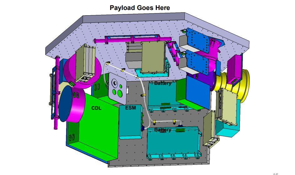
Structure and Mechanisms
The MSV structure is assembled from common, modular deck/panel “building blocks” with features that enable rapid I&T and optimization for numerous missions. The panels are sized by the ISET (Integrated Systems Engineering Team) GBS (General Bus Standard) and made suitable for rapid integration by the SPA (Space Plug-and-play Architecture) electrical/mechanical standards. The MSV reconfigurable bus structure allows a minimal number of structure “components” to be configured into multiple different vehicle configurations. Moreover, it accommodates scalability and rapid reconfigurability through the simple implementation of a SPA standards 5 cm grid pattern.
C&DH (Command and Data Handling)
One of the most groundbreaking innovations of MSV will be in the area of C&DH. For the first time, the SPA (Space Plug-and-Play Architecture) will leave a laboratory environment and be implemented on an operational space system. The following SPA guiding principles are tailor-made to support ORS’s ideals of modularity, scalability, and rapid configurability:
1) Communication Through AIAA Standardized Messages
2) SPA-X databus interfaces : SPA components shall conform to an approved SPA-X interface (-U, -S, -1, -O, etc.) and shall employ well-defined hardware (electrical, mechanical, and signaling) standards to achieve an interface with connective integrity.
3) Self-describing components
4) Query Services : SPA data sources and consumer needs shall be matched through a standard query service in a SOA (Service Oriented Architecture).
5) Self-organizing networks : SPA components shall self-register on the network.
6) Mechanical standards : A SPA device shall be physically mountable on a compliant SPA structure according to one of the applicable SPA mechanical standards.
From these “guiding principles” come several SPA corollary services:
1) Component detection : A SPA system shall automatically detect hardware or software components that are added to the system.
2) Component self-identification : SPA components shall provide information about their functions and use to the system.
3) Command/response messages
4) Publish/subscribe messages : A SPA component’s xTEDS (extensible Transducer Electronic Datasheet) details the command and response messages supported by the component.
5) System monitoring of component status
6) System common time
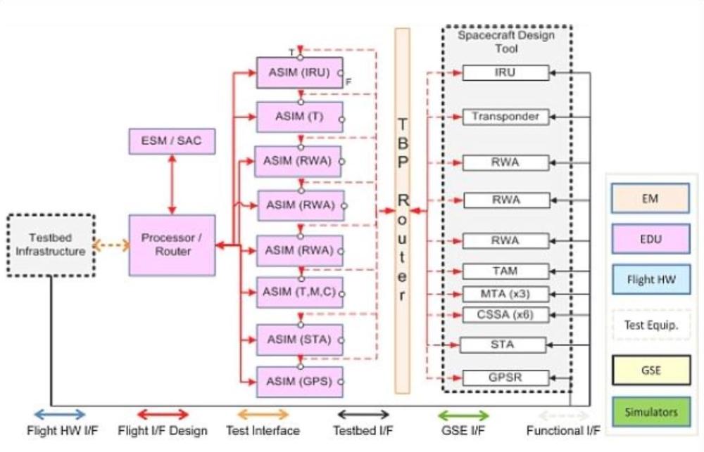
7) Standard mechanical and electrical interfaces : MSV features an SPA-S (SPA-SpaceWire) compliant combined router and power distribution unit that provides standards-compliant power, data, and time distribution, a single-point ground, and a test-bypass capability. All other SPA components are electrically connected to the C&DH architecture via a SPA standard connector. This enables multiple standards-compliant configurations of components to accommodate multiple mission needs. All non-SPA COTS components (e.g., star trackers, GPS, reaction wheels, etc.), which constitute the vast majority of components, are fitted with an ASIM (Appliqué Specific Interface Module) to enable them to electrically connect to SPA-S and SPA avionics.
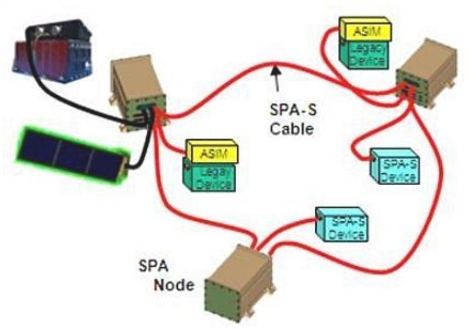
MSV’s SPA avionics are connected via standardized SPA-S harnesses. The SPA ASIM-adapted components can be rapidly reconfigured to accommodate varying missions. Components and their ASIMs are inventoried at call-up after the mission planning system determines the appropriate configuration to accommodate the time-critical ORS need.
ADCS (Attitude Determination and Control Subsystem) and EPS (Electrical Power Subsystem)
ADCS, in keeping with the SPA approach, is modular and scalable at the component level. ADCS components for MSV fit into three general categories : sensors, actuators, and FSW (Flight Software) “components”.
Like ADCS, the EPS follows the SPA approach and is modular and scalable at the component level. For EPS, these components also fit into three categories – power generation, energy storage, and power distribution. In the area of power generation, MSV has scalable solar panels, a scalable number of wings, and in extreme power cases, an articulated solar array option.
TCS (Thermal Control Subsystem)
A luxury afforded the “tactical” spacecraft is the ability to control thermal loading through CONOPS (Concept of Operations). Since ORS spacecraft are designed to serve regional interests, rather than worldwide interests as with our national assets, it is conceivable that operators will alleviate the need for active thermal control by simply turning highload equipment off when the burden becomes too large. However, one innovation of the MSV architecture is the TCIA (Thermal Control Interface Adaptor), which implements the SPA approach and regulates thermal impact to the system at the component level, while providing a mechanical interface from the COTS unit to the SPA structure. Just as the ASIM allows electrical interface of non-SPA to SPA adaptation, the TCIA provides thermal and mechanical adaptation to the architecture.
Communications Subsystem
The communications subsystem includes both SGLS communications for command and control and a CDL (Common Data Link) radio that enables playback of mission data directly to deployed field terminals. For the command and control link to fit within the ORS ground architecture, ORS is imposing the requirement that the space vehicle output encrypted CCSDS (Consultative Committee for Space Data Systems) formatted telemetry and accept encrypted CCSDS formatted commands. CCSDS is the guiding body for space to ground communications, so this ensures a space architecture that is rapidly integrable into existing ground architectures, but it also introduces some unique problems, since SPA messages are necessarily flowing throughout the vehicle and CCSDS messages must flow out of it. To that end, MSV is developing a software component to convert SPA messages into CCSDS messages, while trying to preserve the benefits of each to the maximum extent possible. This recurring theme of “adaptors” to accommodate standards is a conscious sacrifice ORS has made in the interest of scalability and rapid configurability, and the resulting overhead is tracked as a TPM (Technical Performance Parameter).
FSW (Flight Software)
MSV employs a modular, “componentized” FSW approach. The backbone of this approach is the SSM (Satellite Services Manager), which enables SPA messaging between hardware and software components. The graphic of Figure 3 depicts how SPA is used to direct subsystems in support of higher level Mode Agents associated with each nominal activity the spacecraft executes. The subsystem controllers provide an interface for standard subsystem tasks. When different missions arise, new mode agents can be placed into the spacecraft to utilize these subsystems in new or specialized ways.
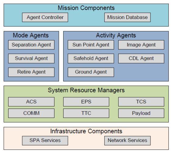
The ORS bus and payload software modular design effort enables similar treatment of other self-contained space vehicle components (e.g., star trackers) based on mission need. This approach maximizes the reuse of software modules previously mission-validated, and provides low risk on future missions. Dependencies between modules are minimized and standardized using a CDD (Common Data Dictionary), allowing for configuration parameters that do not necessitate building and re-verifying the software. This approach, in turn, promotes rapid software checkout and common MOSA high level commands for multiple suppliers’ of modular payload building blocks.
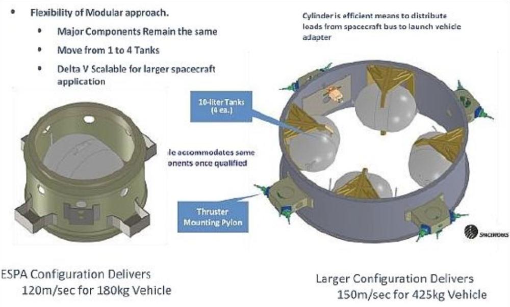
Propulsion
ORS is working with NASA/ARC to develop a modular and scalable propulsion system and plans to demonstrate both an ESPA configuration and a T2E-compatible configuration in the near-term. Moreover, since legacy propulsion systems bring with them fueling campaigns that are incompatible with a Tier-2 response, ORS’s system will be non-toxic (aka “green”) to eliminate the specialized facilities, personnel, and ground-support equipment (and the associated schedule and cost) of a traditional fueling effort.
Test
A delivered test station supporting the Rapid Response Test Environment should:
• Provide test control, power and data interfaces
• Support any combination of actual hardware, software and/or simulations, depending on the test need
• Support subsystem to SV (Space Vehicle) I&T (Integration and Test) level
• Ops testing and training support.
The test environment should support rapid AI&T (Assembly, Integration, and Test), initial satellite vehicle integration and test, be modular for easy support to environmental test, exercise support, launch vehicle integration, and on-orbit anomaly resolution.
The MSV architecture, as well as the ORS employment of that architecture, benefits from SPA’s built-in test strategy – Test Bypass. As the system is incrementally built, Test Bypass allows system level tests and operator training campaigns to proceed in advance of a full set of hardware. Simulated component inputs are supplied by a hardware-in-the-loop rack and introduced at the ASIM, just as inputs from the actual component would be.
Success and Challenges
If historical performance is any indicator, the T2E mission will have just the effect ORS planned when they resolved to develop their architecture in the context of an end-to-end mission. The mission has done a great deal to illuminate both the benefits and challenges of building a MOSA bus architecture and applying it to an Operational need.
Component compatibility (=success): The emergence of MOSA (Modular Open-System Approach) as the new paradigm of space isn't as much of a revolution as a sequence of small victories. Recently ORS experienced one such victory. In 2008, the ORS Office purchased four “COTS” spacecraft components to employ in the MOSA spacecraft architecture they would feature on all of their upcoming missions. The only problem was that neither they, nor anyone else, had invented a MOSA spacecraft architecture. As a result, when they attempted to offer up a free Sodern SED-26 Star Tracker, SGR-07 GPS of SSTL, and the Ithaco IM-203 Magnetometer (a value of approximately $1 M) to ATK for use on their ORS-1 spacecraft, ATK was able to use only the GPS, and they were only able to use that because it was the exact component they had designed into their ORS-1 (Operational Responsive Space-1) spacecraft.
With the award of their MSV contracts, ORS is finally developing the kind of MOSA spacecraft architecture they envisioned since their inception. Their theory is that they can create an architecture that doesn’t require redesign every time a component of that architecture is changed.
This theory was recently put to test when ORS once again offered up their COTS components to NGAS for employment on MSV. NGAS and their MSV spacecraft architecture passed the test with flying colors. Though the COTS Star Tracker and Magnetometer were not the components NGAS had specified for the T2E configuration of their MSV spacecraft, NGAS enthusiastically agreed to employ them on T2E. They made this decision because they assessed that the new components provided the same class of service and, more importantly, because they had developed an architecture in which no single component forced an expensive redesign of the larger system. This marks a significant shift away from the point-design spacecraft towards ORS’s envisioned MOSA spacecraft architecture.
Scalability (=success) : T2E was categorized as an “Enabler” mission to relieve it of the burden of meeting a strictly defined COCOM-imposed requirement set. This had the unfortunate side effect of leaving the T2E with a lot of trade space in their determination of “good enough” on-orbit performance for this type of mission. Two primary trades were to determine how many spot images or how large a strip map area would be necessary for a single-ball asset to have a marketable impact on daily collection needs of a COCOM customer.
Ground architecture limitations aside, the number of spot images collected on a single pass was largely driven by available slew rate. Therefore, a careful reaction wheel selection could be used to tailor performance in this area. NGAS developed the following trade matrix and the ORS Office ultimately decided to employ a unique asymmetric attitude control architecture to match their asymmetric satellite. Larger plug-and-play reaction wheels were aligned with the most challenging axes (in terms of moment of inertia) and a smaller reaction wheel was aligned with the less challenging axis to save mass and power (Table 1). This is an ideal tangible example of how a configuration can be optimized without the NRE (Non-Recurring Engineering) burden of optimizing the larger system to accommodate it.
Trade parameters | Option-1 | Option-2 | Option-3 |
Configuration | (Baseline) | Goodrich 26E700 | Goodrich 26E400 |
Momentum capacity | 16.5 Nms | 26 Nms | 26 Nms |
Max reaction torque | 0.2 Nm | 0.7 Nm | 0.4 Nm |
Speed range | ±5100 rpm | ±2020 rpm | ±2020 rpm |
Mass, single RWA (Reaction Wheel Assembly) | 7.5 kg | 14.5 kg total | 12.4 kg |
Total mass, 3 RWAs | 22.5 kg | 43.5 kg | 37.2 kg |
Dimensions | 26 cm RWA diameter, | 39.4 cm RWA diameter, | 39.4 cm RWA diameter, |
Peak power | 250 W | 380 W | 250 W |
Steady state power at | 28 W at 5100 rpm | 28 W at 2020 rpm | 28 W at 2020 rpm |
Max estimated SV rate at 75% RWA capacity | X-axis: 2.11 º/s | X-axis: 3.33 º/s | X-axis: 3.33 º/s |
Max estimated SV acceleration | X-axis: 0.034 º/s2 | X-axis: 0.119 º/s2 | X-axis: 0.068 º/s2 |
Maneuver time to travel 90º (single axis maneuver) | X-axis: ~73 s | X-axis: ~39 s | X-axis: ~51 s |
Maneuver time to travel 180º (single axis maneuver) | X-axis: ~103 s | X-axis: ~55 s | X-axis: ~73 s |
TRL (Technology Readiness Level) | TRL-9 | TRL-9 | TRL-9 |
As it turns out, increased strip map area collect capability is not a factor of slew rate as much as available power. Therefore the appropriate selection of power generation (solar array area) and power storage (batteries) capability could be used to tailor performance in this area. In a similar fashion to the previous trade, NGAS put together the following set of configurations to give ORS the flexibility to match performance to requirements (Table 2).
Trade parameters | Option-1 | Option-2 | Option-3 |
Configuration | Baseline: 3 orbits in a row for: eclipse +10 min PL Ops +10 min CDL Comm Ops+slew | 4 orbits in a row for: | 7 orbits in a row for: |
Total slew time & assumption | Slew from/to sun point twice per orbit for a total slew time of 8 min per orbit | Slew from/to sun point twice per orbit for a total slew time of 8 min per orbit | Slew from/to sun point twice per orbit for a total slew time of 8 min per orbit |
SA load | 600 W | 600 W | 600 W |
Battery | 2 LCROSS | Add 2 LCROSS batteries, 6.5 kg each (4 total) | Remove existing LCROSS batteries. Add 2 JWST batteries, 19.8 kg each, W=37.7 cm, L=26.5 cm, H=17.7 cm |
SA configuration (No of wings & panels) | 3 wings, 6 panels | No change from baseline, except possibility of additional ESM (TBS) | Need to add ons SAC module and one ESM |
Dimension | See MEL | See MEL | Each battery: W-37.7 cm, L=26.5 cm, H=17.7 cm |
SA on SB configuration | SRR package | - | Added 1 wing, moved 1 wing 60º to make layout symmetric |
Mass (SB+ Payload) | 244.95 kg | 258.34 kg (8.34 kg above requirements) | 276.27 kg (26.27 kg above requirements) |
MOI (SB+Payload) | bcx=281 kgm2 | bcx=286 kgm2 | bcx=311 kgm2 |
Agility (slew&acceleration) | TBS | TBS | TBS |
Mechanical interface accommodation | N/A | No impact | No impact |
These two preliminary trades offer great promise for ORS and their vision that the MSV architecture will be able to supply an optimized configuration of their scalable architecture to accommodate a wide range of specific mission needs. Moreover, when the situation warrants, they can adopt a “capability driven approach” and factor in bounding constraints, such as a requirement to fit in the launch envelope of a Minotaur-1, along with COCOM (Combatant Command) needs to converge on a solution, as in the case of T2E.
Uncontrollable processes (= challenge) : Technology (e.g., SPA) was a solution for many of the impediments to rapid configurability, but some of the most dramatic hurdles for a true ORS Tier-2 response are non-technical. ORS endeavors to build a reconfigurable architecture and employ it in response to time-critical COCOM needs. However, processes such as Information Assurance, Frequency Management, and Range Safety, as well as the personnel that implement them, don’t share the same mandate for rapid configurability on ORS Tier-2 timelines. As a result, ORS will likely feature a rapidly configurable space and ground architecture on the T2E mission, but only be able to employ it in a simulated environment.
References
1) Charles J. Finley, Kimberly Richards, Jose C. Cabanillas, III, Denny Gudea, Phil Katz, Sarah Ray, George Moretti, Demosthenes Tsairides, “HOW ORS – Modular Space Vehicle on the T2E Mission,” Proceedings of the 25th Annual AIAA/USU Conference on Small Satellites, Logan, UT, USA, Aug. 8-11, 2011, paper: SSC11-VII-4
2) Jeffry S. Welsh, “Open Manufacturing Industry Days – ORS Perspective,” Arlington, VA, February 16, 2011, URL: http://www.darpa.mil/WorkArea/DownloadAsset.aspx?id=2147483666
The information compiled and edited in this article was provided by Herbert J. Kramer from his documentation of: ”Observation of the Earth and Its Environment: Survey of Missions and Sensors” (Springer Verlag) as well as many other sources after the publication of the 4th edition in 2002. - Comments and corrections to this article are always welcome for further updates (eoportal@symbios.space).