SUNSAT (Stellenbosch University Satellite)
EO
Mission complete
Other
Communications
Quick facts
Overview
| Mission type | EO |
| Agency | Uni of Stellenbosh, SANSA |
| Mission status | Mission complete |
| Launch date | 23 Feb 1999 |
| End of life date | 19 Jan 2001 |
| Instruments | TRSR |
| Instrument type | Other, Communications, Data collection |
| CEOS EO Handbook | See SUNSAT (Stellenbosch University Satellite) summary |
SUNSAT (Stellenbosch University Satellite)
SUNSAT is an advanced microsatellite program, developed by graduate students of the Department of Electrical and Electronic Engineering at Stellenbosch University, Stellenbosch, South Africa (Stellenbosch University is located about 50 km east of Cape Town). The overall objective is to demonstrate proven and new technologies in the fields of remote sensing, spacecraft control, the solid Earth sciences, and to provide services (mail box, speech and data relay experiments) to the AMSAT community. 1) 2) 3)
Background
The South African microsatellite industry has its roots in the SUNSAT academic program that started in 1992 at Stellenbosch University (SU). A spin-off of this program was the formation of SunSpace and Information Systems (Pty) Ltd. in March 2000 - an associate company of SU - aimed at commercializing satellite technology developed at the University of Stellenbosch.
Spacecraft
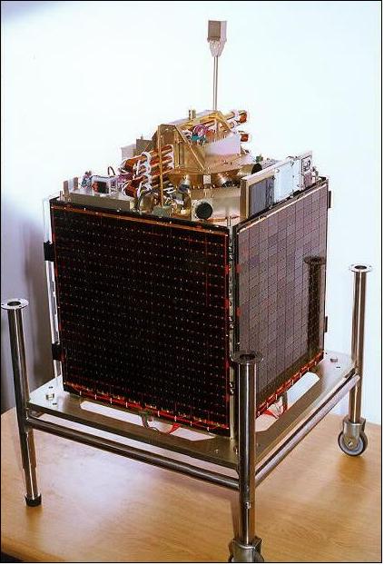
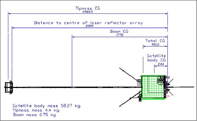
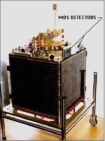
The spacecraft structure features a tray-based design of proven flexibility and stability. The trays are sandwiched (stacked) between base and top plates of the S/C structure, containing all subsystems and payload instruments. The dimensions of the box-like spacecraft are: 45 cm x 45 cm x 62 cm; spacecraft mass = 64 kg; power = 30 W from body-mounted solar panels and rechargeable NiCd batteries; two on-board computers and an attitude processor. 4)
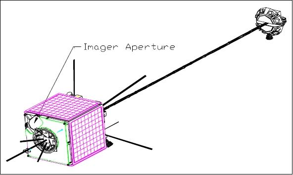
SUNSAT is stabilized with a gravity-gradient boom (2.5 m boom with a 4.4 kg tip mass consisting of 8 laser retroreflectors, a star sensor and a magnetometer). The S/C is pointing toward nadir. Attitude actuators are: 3-axis reaction wheels (to provide fine-pointing during imaging), 3-axis magnetic torquer coils (continuous control capability). Attitude sensors are: 3-axis fluxgate magnetometer, 2-axis horizon sensor (CCD array to obtain pitch and roll to an accuracy of 0.02º), a fine slit sun sensor (CCD array, to obtain yaw information to an accuracy of <0.1º), a second star sensor to measure a star positions with accuracies of < 12 arcseconds. A small spacecraft spin is provided during normal operations; however, not during imaging periods.
The lower tray is 12 cm high to contain the imager, which fits diagonally across the tray. The Earth below is viewed via a 45º mirror. The diagonal tube contains the optics and CCD-related electronics, and the tube can be rotated left/right for cross-track or stereo viewing.
The other electronics in SUNSAT are packaged in trays for power control, telemetry, telecommand, VHF communications, UHF communications. On Board Computer 1 (OBC1), OBC2, RAM disk, ADCS (Attitude Determination and Control System), and top plate. The top plate carries horizon, sun, and star sensors, and also holds the deployable boom. 5) 6) 7)
The satellite features two OBCs (Onboard Computers) and a dedicated ADCS (Attitude Determination and Control Subsystem) processor. The two OBCs are an Intel 188EC and Intel 386EX. The ADCS processor is a T800 transputer. In addition, there are numerous support processors (mostly 80C31 micro controllers) with dedicated functions.
RF Communications
SUNSAT's communications employ the store-and-forward concept and the PACSAT protocol suite to provide the services for amateur radio communications (VHF, UHF, L- and S-bands), data downlinking VHF (145.825 MHz), UHF (436.25 & 436.30 MHz), S-band (1260 or 2400 MHz), data collection (VHF, UHF), and spacecraft control. Different frequencies are at times required for different services. The power amplifiers have 5 W output at VHF and S-band and 10 W output at UHF. The S-band downlink permits a data rate of 40 Mbit/s in QPSK modulation. A 64 MByte RAM disk is being used for image storage.
The SUNSAT spacecraft was operated from the ground station of the Department of Electrical Engineering at Stellenbosch University.
Launch
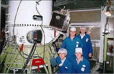
SUNSAT was launched on a Delta-II vehicle from VAFB, CA on Feb. 23, 1999 as a secondary payload along with the Ørsted satellite of Denmark. The prime satellite was ARGOS (P91-1) of DoD, USA.
SUNSAT has been allocated the Amateur designation of SO-35 (SUNSAT Oscar 35) and is supporting Amateur radio FM repeater operations in South Africa and the USA. The launch of SUNSAT was sponsored by NASA - in exchange for NASA scientific instruments that were part of the SUNSAT payload.
Orbit
Sun-synchronous orbit, altitude = 655 km x 857 km, inclination = 98.4º, period = 100 minutes. The slight elliptical orbit was dictated by the science requirements of the Ørsted satellite which was the first secondary payload to be deployed.
Status of the SUNSAT Mission
The last contact with SUNSAT took place on Jan. 19, 2001 after nearly two years of operations since launch (hardware failure). The project exceeded all its original goals.
Sensor Complement
HRI (High Resolution Imager)
HRI is a three-color CCD pushbroom imager, developed jointly by Stellenbosch University, CSIR (Council for Scientific Research, South Africa), and KAIST (Korean Advanced Institute of Science and Technology). The imager consists of a single 10 cm diameter optical tube assembly, comprising a lens system, penta-prism with dichroic color splitter, three vertically mounted linear CCD detectors (TC104 of Texas Instruments with 3456 pixels/line) and their clock drivers and output buffers. The optical tube is mounted diagonally across the bottom of the S/C on bearings, and can be rotated by a stepper motor. Stereo images are taken with the optical tube horizontal and normal to the velocity vector (forward or backwards pitching of up to 24º to obtain various stereo base/height ratios). Images to the left or right of the ground track can be taken by placing the optical tube parallel to the velocity vector. A 64 MByte RAM enables an image to be stored for subsequent downlinking. The spectral band selection is identical to that of TM of the Landsat missions (LS-2, -3, and -4). A ground pointing accuracy of the imagery within 1 km is the goal.
Imagery from a PAL TV camera is transmitted in real-time via S-band to a ground station at Stellenbosch. The HRI downlink is via the VHF and UHF transmitters, because of a malfunction of the high-speed modem, HRI transmission could not occur in S-band, as planned originally.
The reaction wheels of the attitude control system provide 3-axis stabilization during imaging periods. Fast target pointing (body pointing of the S/C) is accomplished with an axis-rotation algorithm.
Parameter | Value | Parameter | Value |
Spectral band 1 | 0.52 - 0.61 µm | Lens focal length | 570 mm |
Spectral band 2 | 0.61 - 0.70 µm | Aperture diameter | 100 mm |
Spectral band 3 | 0.76 - 0.87 µm | Spatial resolution | 15 m (800 km orbit) |
Linear CCD detectors | 3 x TC104 (one/band) | Swath width | 51 km (800 km orbit) |
Nr. of pixels/detector | 3456 (active), 3490 total | FOV | 3.715º |
Sensor pixel size | 10.7 µm | Line scan rate | 400 lines/s |
Total source data rate | 70.5 Mbit/s | Quantization | 8 bit |
On hindsight, the 15 m spatial resolution multispectral imagery provided by the HRI instrument on SUNSAT represented the best high-resolution observations taken by a microsatellite at the start of the 21st century.
TRSR (TurboRogue Space Receiver)
TRSR is a NASA/JPL-provided advanced GPS receiver (TurboRogue, built by Allen Osborne Associates) to perform experiments in atmospheric, ionospheric, and gravity mapping. The receiver is designed to overcome many of the anti-spoofing difficulties experienced by a GPS receiver on TOPEX/Poseidon. The receiver performs phase measurements of both GPS frequencies L1 and L2, and derives pseudoranges from these measurements. The dual-frequency occultation technique employed measures retarded signals (atmospheric propagation delays) which permit the derivation of atmospheric profiles of density, pressure, and temperature (or moisture) in an altitude range from 85 km to the ground. The co-location of the GPS receiver and the satellite laser retroreflector permit a check of the two reference frame systems for GPS and SLR geodesy.
• Objectives for atmospheric mapping: to improve occultation measurements of the troposphere to measure temperature (resolution of 1º C) and water vapor. Continuous GPS operations in occultation mode provides over 300 globally distributed measurements per day.
• Ionospheric objectives: continuous monitoring of the ionospheric structure. TurboRogue measures the arrival times of the GPS signals at two frequencies. Hence, the electron content of the ionosphere is measured in terms of the differential arrival times of these two signals.
• Geodesy and gravity objectives: the GPS and SLR systems of SUNSAT are being used for precise orbit determination. There are also plans to monitor the long wavelength gravity field and its variation in time.
MIS (Meteoroid Impact Sensor)
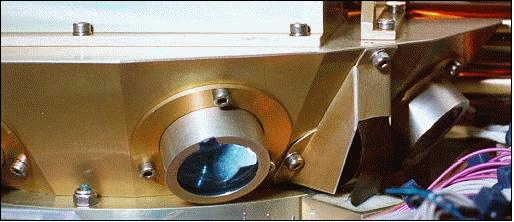
MIS is of NASA/LaRC within the SEE program. The objective is to monitor the meteoroid and small mass man-made debris population. The experiment, which utilizes MOS (Metal-Oxide Semiconductor) detectors, is similar in concept and design to OMDC (Orbiting Meteoroid & Debris Counting) experiment flown on the Clementine spacecraft. When space debris or meteoroids particles impact the sensor, then the sensor location and time of impact is stored and down linked for data analysis. From this information, space-debris flux and directionality can be assessed. 8)
Magnetometer Assembly
The magnetometer assembly was provided by Hermanus Observatory, South Africa). The magnetometer experiment was collocated with the star camera in the tip mass of the gravity boom, providing a complementary measurement of the magnetic field to the Ørsted geomagnetic satellite. The magnetic field experiment onboard the SUNSAT satellite consists of two fluxgate magnetometers, called Orimag and Scimag, both built and calibrated by the Hermanus Magnetic Observatory. Orimag is mainly used for orientation control purposes on SUNSAT, while Scimag, mounted on the boom of 2.2 m in length was designed to perform geomagnetic field observations, employing standard navigation fluxgate technology. 9)
LRA (Laser Retroreflector Array)
The passive LRA is a hemispherical annulus (boom and S/C-mounted, provided by NASA/GSFC). It offers SLR (Satellite Laser Ranging) measurements from many ground stations of ILRS (International Laser Ranging Service). The design features eight encapsulated retroreflectors (corner cubes) inserted into a ring configuration azimuthally about the tip mass.
References
1) A. Schoonwinkel, G. W. Milne, S. Mostert , W. H. Steyn, K. van der Westhuizen, “Pre-Flight Performance of SUNSAT, South Africa's First Remote Sensing and Packet Communications Microsatellite,” Proceedings of the 10th Annual AIAA/USU Conference on Small Satellites, Sept. 16-19, 1996, URL: http://staff.ee.sun.ac.za/whsteyn/Papers/USU96_Sunsat.pdf
2) G. W. Milne, A. Schoonwinkel, J. J. Du Plessis, S. Mostert, W. H. Steyn, K. van der Westhuizen, D. A. van der Merwe, H. Grobler, J.-A. Koekemoer, N. Steenkamp, “SUNSAT - Launch and first Six Month's Orbital Performance,” Proceedings of the 13th Annual AIAA/USU Conference on Small Satellites, Aug. 23-26, 1999, Logan Utah, SSC99-1-4
3) S. Mostert, T. Cronje, F. du Plessis, “The SUNSAT Micro Satellite Program: Technical performance and limits of imaging micro satellites,” URL: http://www.jamsat.or.jp/oscar/sunsat/mirror/sspapers/cnes.pdf
4) C. Hardingham, J. Simpson, S. Wood, T. A. Cross, J. F. Uys, “Experimental solar cells on the SUNSAT microsatellite,” 26th IEEE Photovoltaic Specialists Conference, Anaheim, CA, USA, Sept. 29 to Oct. 3, 1997, pp. 1015-1018
5) N. Morton, S. Mostert, “African Satellite Constellation for Transnational Resource Management Towards Disaster Preventation,” UN Regional Workshop on the Use of Space Technology for Disaster Management for Africa Addis Ababa, 1-5 July 2002
6) S. Mostert , J. A. Koekemoer , “The science and engineering payloads and experiments on SUNSAT,” Acta Astronautica, Vol 41, No 4-10, August-November 1997
7) SunSat,1999-008C, http://centaur.sstl.co.uk/sshp/micro/micro99.html
8) http://setas-www.larc.nasa.gov/sunsat/SUNSAT.html
9) P. B. Kotzé, B. Langenhoven, T. Risbo, “Magnetic field experiment on the SUNSAT satellite,” Journal of Geodynamics, Vol. 33, Issues 1-2, January-March 2002, pp. 21-28
The information compiled and edited in this article was provided by Herbert J. Kramer from his documentation of: ”Observation of the Earth and Its Environment: Survey of Missions and Sensors” (Springer Verlag) as well as many other sources after the publication of the 4th edition in 2002. - Comments and corrections to this article are always welcome for further updates (eoportal@symbios.space).