SumbandilaSat ("Lead the Way" From Venda Language - Formerly ZASat-002)
EO
Atmosphere
Ocean
Atmospheric Temperature Fields
Quick facts
Overview
| Mission type | EO |
| Agency | Uni of Stellenbosh, SANSA |
| Mission status | Mission complete |
| Launch date | 18 Sep 2009 |
| End of life date | 24 Jan 2012 |
| Measurement domain | Atmosphere, Ocean, Land, Snow & Ice |
| Measurement category | Atmospheric Temperature Fields, Aerosols, Multi-purpose imagery (ocean), Multi-purpose imagery (land), Vegetation, Albedo and reflectance, Sea ice cover, edge and thickness |
| Measurement detailed | Ocean imagery and water leaving spectral radiance, Land surface imagery, Vegetation type, Fire fractional cover, Earth surface albedo, Leaf Area Index (LAI), Land cover, Atmospheric temperature (column/profile), Sea-ice cover, Normalized Differential Vegetation Index (NDVI), Iceberg fractional cover, Photosynthetically Active Radiation (PAR), Fraction of Absorbed PAR (FAPAR), Glacier cover, Soil type, Visibility |
| Instruments | MSI (SumbandilaSat) |
| Instrument type | Imaging multi-spectral radiometers (vis/IR) |
| CEOS EO Handbook | See SumbandilaSat ("Lead the Way" From Venda Language - Formerly ZASat-002) summary |
SumbandilaSat ("Lead the Way" From Venda Language - Formerly ZASat-002)
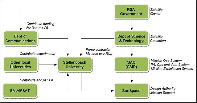
SumbandilaSat (formerly ZASat-002) is a pathfinder mission of the University of Stellenbosch, SunSpace (Pty) Ltd. (a spin-off company of the University of Stellenbosch), and SAC (Satellite Application Center) of CSIR (Council for Scientific and Industrial Research), Pretoria, South Africa. In May 2005, the DST (Department of Science and Technology) of the South African Government commissioned Stellenbosch University to develop the ZASat pathfinder satellite program, a technology demonstration in conjunction with the South African industry. The ZASat program was officially announced by the SA Department of Science and Technology (DST) on October 3, 2005. ZASat become in fact a National Space Program Initiative, consisting of two parts: 1) 2) 3) 4) 5)
1) The development of a microsatellite bus by SunSpace as prime contractor 6)
2) The research and human resource development is largely the responsibility of Stellenbosch University over a period of 4 years (a considerable number of students will be involved in research work on various aspects of remote sensing satellites and payloads).
Note: The abbreviation and country code `ZA' for `South Africa' is of Dutch origin - when the country was named "Zuid-Afrika." Dutch was the official language in South Africa, before being replaced in the 1920s by Afrikaans (a Germanic language of Dutch, German, English and French roots spoken mainly in South Africa and Namibia), in which the name of the country is `Suid-Afrika'.
On July 31, 2006, the ZA-002 mission/program was renamed by the South African Government to SumbandilaSat, meaning `lead the way' in Tshivenda (an excellent name for a pathfinder mission). The name Sumbandila was among the more than 3000 entries received in a national competition that was initiated by the Department of Science and Technology (DST) and implemented through the South African Agency for Science and Technology Advancement (SAASTA) in the first half of 2006. The three winners were grade 7 to 12 students from High Schools in Pretoria, Cape Town, and Durban, respectively. 7) 8)
Spacecraft
The ZASat-002 pathfinder microsatellite bus has been designed as a multi-sensor platform, based on the MMSat bus (an internal name - designating a modular and multispectral design concept), developed in the aftermath of the SUNSAT project (SUNSAT, with a launch in Feb. 1999, is considered to be the -001 mission). The following characteristics apply to the MMSat bus:
• Designed for a nominal spacecraft mass of 82 kg and sun-synchronous orbits (500-700 km altitude range) with a design life of 3 years
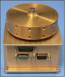
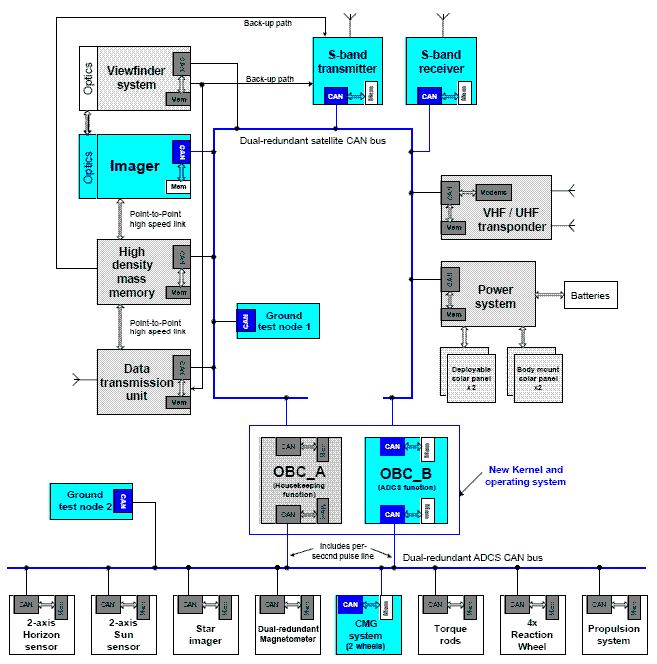
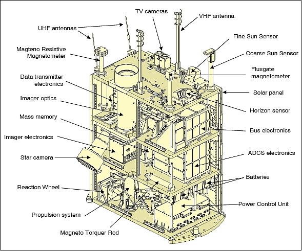
• Fully 3-axis reaction wheel satellite stabilization with magnetic momentum management (agile spacecraft which can be re-oriented to successive ground targets within 30 seconds). Attitude is sensed with the following devices: horizon, fine-sun, coarse-sun sensors, star camera, magnetometer(s), and fiber-optic gyros (FOGs); actuation is provided with reaction wheels and magnetorquers. 9) 10)
Wheel control modes:
1) Y-momentum wheel mode:
- +Y-body axis aligned to sun vector
- Control pitch for +Z-facet ~ towards Earth
- Nutation damping & Y-wheel momentum maintenance with magnetic x-product control.
2) Zero-bias 3-axis reaction wheel mode:
- Quaternion feedback PD control
- Sun pointing & nadir pointing (eclipse)
- Magnetic x-product for momentum management.
3) X/Y wheel control mode (lost Z-wheel):
- Nadir pointing & biased Y-wheel momentum
- Control Z-axis using X-wheel through roll/yaw coupling
- Magnetic X-prod for X/Y wheel momentum management & Z-axis yaw angle control.
Sensors and actuators | Type | Range/FOV | Accuracy (rms) |
Magnetometer | 3-axis fluxgate | ± 60 µT | < 50 nT |
Sun sensors | 2-axis CMOS matrix | ± 45º | < 0.2º |
FSS (Fine Sun Sensor) | Matrix |
|
|
CSS (Coarse Sun Sensor) | 6 x solar cells | Full sphere | < 10º |
Earth horizon sensor | 2-axis CMOS matrix | ± 40º | < 0.2º |
Sensor | Matrix |
|
|
Star Tracker | CCD matrix sensor | 12.2º x 18.6º | < 20 arcsec |
Rate sensor | 3-axis FOG | ± 8 º/s | < 5 milli-degree/s |
Reaction wheel | 3-axis BDC motor | ± 8000 rpm | < 1 rpm |
Magnetorquer | 3-axis ferromagnetic coil | ± 5 Am2 | < 0.02 Am2 |
Rod | Magnetic coil |
|
|
TCS (Thermal Control Subsystem): Thermal control is done through a passive TCS that includes coatings, tapes and internal conduction paths. Onboard temperature measurements of major components are made possible via one-wires, thermocouples and thermistors. The TCS development methodology corresponded to the recommendations of the ECSS (European Cooperation for Space Standardization). 11)
• Power system to ensure 65 W orbit average power to an imager payload at EOL (End of Life)
• Target off-pointing (roll), FMC (Forward Motion Compensation) and stereoscopic imaging capability. FMC is used for spotlight imaging - a process whereby the body-pointing spacecraft is looking into a spot (a small target on the ground) to achieve longer integration times of the detectors while progressing along its orbital path. This FMC technique permits a) observations at lower lighting conditions, and b) enables also video camera imaging.
• Optional provision of video joystick steering for manual target acquisition
• Dual redundant onboard computers with EDAC protection and 32 MByte file system
• Provision of a butane propulsion system for orbit maintenance. Sufficient propellant is included to maintain a satisfactory orbit for 3-4 years.
• GPS receiver and onboard orbit propagator to ensure a 50 m (1σ) orbit position accuracy
• S-band transmission (in particular, this is the downlink for imaging data)
• Redundant VHF/UHF telecommand and telemetry transmitters and receivers (TT&C data)
• Onboard mass data storage capacity of 24 GByte (total)
• Provision of a cross-track body-pointing capability of the microsatellite (use of oblique sideways viewing to roll angles of up to 30º) to increase the FOR (Field of Regard) and hence the revisit time of targets of interest
• Two operational modes are provided: 1) Diary-scheduled mode allows pre-programming of the satellite to image a specific area, even at a remote location, 2) Viewfinder mode allows the satellite to be interactively steered from the ground station with a joystick, while within communication range.
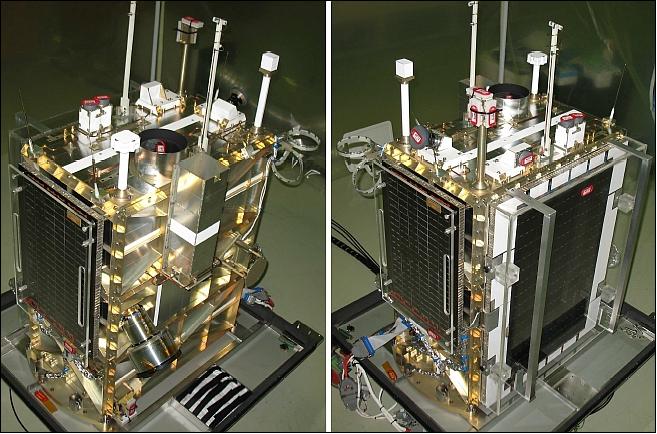
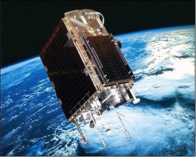
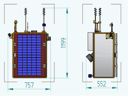
The ZASat-002 pathfinder has a launch mass of 82 kg, using a box-like structure of size: 70 cm x 50 cm x 80 cm, and one body-mounted solar panel. The design life is 3 years.
Launch
The ZASat-002 pathfinder spacecraft (SumbandilaSat) was launched on Sept. 17, 2009 as a secondary payload to the Meteor-M-1 primary mission of Roskosmos/Roshydromet/Planeta, Russia. The launch vehicle was a Soyuz-2.1b/Fregat vehicle, and the launch site was Baikonur, Kazakhstan.
The six secondary payloads on this flight were: 12) 13)
• Tatiana-2, also spelling of Tatyana-2 (Universitetskiy, 120 kg), a microsatellite of the Lomonosov Moscow State University (MSU), Moscow
• Sterkh-2 (a microsatellite of ~ 171 kg), will serve as Cospas-12 in the COSPAS-S&RSAT search & rescue network.. Sterkh-2 was built by PO Polyot.
• UGATUSat (a microsatellite of 30 kg) of Ufa State Aviation Technical University (UGATU), Russia, built by PO Polyot.
• ZASat-002 (SumbandilaSat, a microsatellite of 82 kg) of SunSpace/DST, South Africa. 14)
• BLITS (Ball Lens In the Space), a nanosatellite of 7.53 kg (sphere, reflector). BLITS was developed and manufactured by the IPIE center, under a 2006 agreement between Roskosmos and International Laser Ranging Service (ILRS). The purpose of the mission is experimental verification of the spherical glass retroreflector satellite concept.
• IRIS , an experimental unit attached to the Fregat upper stage, built be NPO Lavochkin and designed to test an inflatable and solidifying material in space.
Orbit
Sun-synchronous near-circular orbit, altitude = 504 km, inclination = 98º, local equatorial crossing time at 9:00 hours. A revisit time of any target region of 3-4 days is provided.
Note: The launch vehicle placed the ZA-002/SumbandilaSat spacecraft into an orbit of 492 km x 504 km in altitude. All other satellites of the mission were placed into an orbit of 832 km altitude.
Notes on the Project Launch Delays
• The launch was contracted directly by the South African government, the DST (Department of Science and Technology), and was originally scheduled to take place on a modified Shtil rocket from the Barents Sea on Dec. 5, 2006.
• SunSpace designed, developed and tested the satellite under huge time constraints, with final delivery of the flight model to its owner, DST, in November 2006. The satellite architecture was entirely new and represented the first opportunity to flight test the SunSpace next generation of satellite subsystems.
• Due to political reasons, the launch unfortunately did not go ahead as planned. After two years of frustrating delays, a launch opportunity on a Soyuz-2.1b was negotiated by the DST, in the process shifting SumbandilaSat from a primary to a secondary payload. The rocket finally lifted off on 17 Sept 2009, inserting SumbandilaSat into a perfect sun-synchronous orbit at 504 km, after first releasing the main payload (Meteor-M) and other secondaries.
Mission Status
• The satellite's primary mission has officially come to an end in July 2011. The spacecraft is no longer operational for imaging due to a failure of the magnetic control system's power switch. Since August 2011, the project continues to communicate with the satellite several times a week (also in 2012). The satellite, however, does not have any battery power left, nor any active attitude control. The project is looking into ways to salvage limited functionality on an experimental payload. The satellite will remain in polar orbit for an estimated three more years. 15) 16)
• September 11, 2011 marks the two year anniversary of on-orbit operations of SumbandilaSat. A total of 1909 images were successfully received in this period. 17)
- Propulsion system: The satellite orbit is currently experiencing much higher atmospheric density due to the eleven year peak in solar activity resulting in orbital altitude reducing by about 1.5 m per orbit. To mitigate the drop in altitude, the butane propulsion system was used during the period April 14-16, 2011 to execute 20 firings of 1 minute each to raise and circularize the orbit of SumbandilaSat from its 498 km x 504 km orbit at the time. The current orbit is 501 km x 506 km.
- In 2011, SumbandilaSat is operated from the SANSA (South African National Space Agency) SSO (SANSA Space Operations) ground station in Pretoria, supported on an ad-hoc basis by Sunspace via the ESL (Electronic Systems Laboratory) ground station in Stellenbosch. Note: SSO was formerly known as SAC (Satellite Application Center).
- Spacecraft status: Up until July 2011, SumbandilaSat was in a stable attitude in a modified Y-Thompson spin mode. However, at the end of July / beginning of August 2011, there was a PDU (Power Distribution Unit) upset which caused both PDUs of ADCS to go offline. This meant that MIUB (Magnetic Interface Unit B), which controls the torque coils and reads the magnetometer in order to keep the satellite stabilized, is switched off.
The current state of the satellite is that the MIUB is switched off due to the power switch anomaly. As a result, normal communication with the satellite cannot progress.
Each power switch has also a backup controller, but the backup controller has experienced an anomaly a few months ago. The result is that the satellite is tumbling in an uncontrolled state and that the main solar panel is not facing the sun for long enough duration to keep the batteries charged continuously. As a result, the batteries discharge and the satellite switches off. As the satellite tumbles, there are periods when there is enough sun on the panel to charge the batteries and to keep the satellite running for a while (a day or two). In this instance, the OBC is switched on and telemetry is downloaded. However, when the rotation of the satellite takes the panel away from the sun for too long, the batteries again discharge and the satellite switches off.
As long as MIUB is not active, no control of the satellite attitude and imaging is possible. In early autumn of 2011, SunSpace satellite specialists were working on alternate attempts to regain control of the two malfunctioning PDUs. If successful with either one of the two, the MIUB will be able to switch on again and normal operations should be able to resume.
Apart from the PDU anomaly, the satellite is in good health and all sub-systems are working. The batteries are being stressed by the deep discharge cycles, but at present nothing can be done about this. A benefit of this anomaly is that the battery temperature has come down (which enhances the life expectancy of batteries in general) since the solar panel is not continuously facing the sun anymore (Ref. 17).
• In June 2011, SumbandilaSat was damaged during a solar storm. The power supply to SumbandilaSat's onboard computer stopped working and the satellite stopped sending back images.
• In September 2010, more than 320 high-resolution images have been collected worldwide. This represents an equivalent of almost 85% of the total land surface area of South Africa. All images are being processed by the Satellite Applications Centre (SAC) – a division of the Council for Scientific and Industrial Research (CSIR), South Africa (Ref. 27). 18)
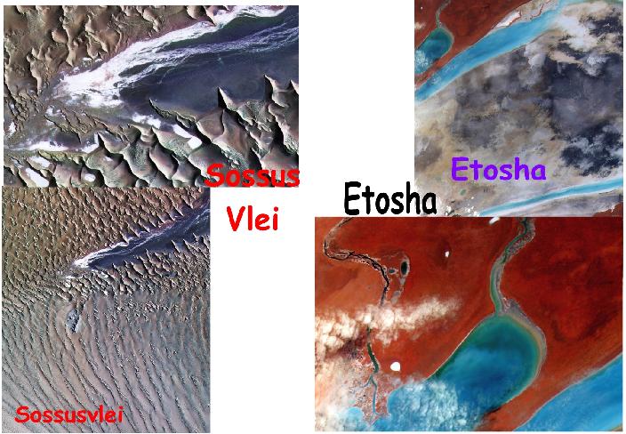
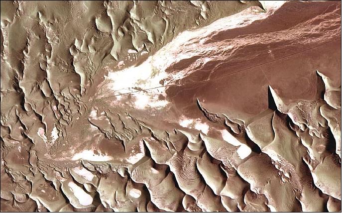
Legend to Figure 8: Sossusvlei is a salt an clay pan surrounded by high red dunes, located in the southern part of the Namib Desert, in the Namib-Naukluft National Park of Namibia.
The Etosha National Park in northwestern Namibia was established in 1907 when Namibia was a German colony known as South West Africa. The Park is one of the largest, oldest and richest of fauna of the whole African continent, where the presence of many springs and sparse vegetation allow tourists to have an incredible contact with animals. Developed in a protected area of over 22,000 km2 (the original park had a size of 100,000 km2) , it is a true sanctuary - a very large and significant area in which wildlife is protected.
• The pushbroom imager is still able to scan target areas accurately using a FMC4 (Forward Motion Compensation) method, simultaneously doing a roll offset maneuver for cross track scanning. Target tracking by pointing the high data rate S-band antenna is also successfully demonstrated, while allowing the satellite to freely rotate around the antenna boresight during these periods (Ref. 9).
• Subsequent to the commissioning, the Y-wheel started to produce an anomaly where it will trip it's power switch periodically. The reason for this anomaly has not been determined and resolved yet. However, the project believes this is not a permanent failure and can perhaps be resolved by changing the Y-wheel microcontroller code. In the meantime the satellite is controlled in a safe mode Y-Thompson spin. - FMC4 imaging is still possible by utilizing a novel magnetic torquer controller to phase the pitch angle to zero at image centre (T0), while also controlling the body spin accurately at the FMC4 pitch rate (Ref. 9).
• The spacecraft was commissioned and became operational on March 1, 2010. From now on, mission control was handed over from SunSpace to SAC (Satellite Applications Centre) at Hartebeetshoek near Pretoria in South Africa, as requested by DST. 19)
Although a hugely successful mission thus far, the past six months have unfortunately not been without incident. The satellite suffered a permanent loss of the Z-axis reaction wheel early on during commissioning, where after the ADCS algorithms have been adapted so as to still allow for controlled imaging with the remaining two wheels - Yaw-control was then slightly impeded and the off-Nadir Roll angle limited to ±20º.
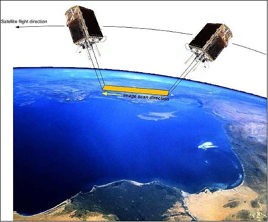
Prior to the loss of the Z-axis reaction wheel, the pitch rate was 3-axis controlled and the images scanned from "front" to "back". In the current modified mode, the pitch rate is controlled by the magneto torquers only and altered to 0.955º/s so that images can be scanned "back" to "front" as shown in Figure 10 (Ref. 27).
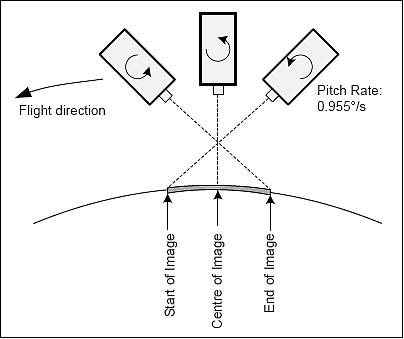
The satellite is now in a permanent momentum-stabilized, modified Y-Thompson spin mode. Prior to an image being taken, the pitch rate of the satellite is phased such that the imager aperture would point nadir when the satellite is directly overhead the desired target. During imaging, the off-nadir roll angle is actively controlled with the remaining X-axis wheel, within a ±5º target band.
• Due to a power system anomaly, the project sadly lost access to one of the two CCD control boards. Each control board interfaces to one three-color CCD. The board lost contains the green, xantrophyl and blue spectral bands, and the remaining board the red, red-edge and NIR (Near-Infrared) bands. 20)
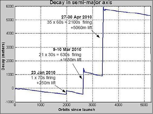
• The orbit altitude of the spacecraft has been corrected at three instances in time. Figure 11 shows the propulsion system result during firings to raise the semimajor axis of SumbandilaSat. The firings were all scheduled at the orbit apogee, to raise the orbit perigee and lower the orbit eccentricity.
- The first firing happened 2000 orbits after launch on the 23rd of January 2010, when a thruster pulse of 70 seconds was applied. At that stage the orbit SMA (Semimajor Axis) already decayed by about 450 m due to aerodynamic drag. This first firing increased the SMA by 250 m.
- The second set of firings happened during the period of March 9-10, 2010 when 21 firings of 30 seconds each were applied on successive apogee crossings. These firings led to a SMA increase of about 1650 m.
- The third set of firings happened during the period of April 27-30, 2010 when 35 firings of 60 seconds each were applied at apogee. This last set of firings resulted in an increase of about 5060 m leading to a final orbit of 502 by 505 km (compared to the initial orbit after launcher separation of 492 by 505 km 7.5 months earlier).
• In December 2009, SumbandilaSat is making two passes over South Africa every day. The spacecraft and its payload are being commissioned. Many high-resolution images have been downloaded and analyzed for further calibration and performance improvement. 21) 22)
• By November 2009, the following commissioning milestones had been attained (Ref. 27):
- Satellite 3-axis stabilized
- On-Board Computer (OBC) fully operational
- Various code uploads executed
- Viewfinder functionality verified
- SA-AMSAT payload activated and SO-67 (SumbandilaSat Oscar 67) designator assigned by AMSAT-NA.
- First high-resolution images taken and downloaded
- Horizon and Fine Sun Sensors commissioned.
• After separation from the Fregat launcher stage the satellite was randomly tumbling. Fifteen minutes after separation during the first ground station pass, the total angular tumbling rate was estimated at 3.5º/s, within the launch vehicle specification of 10º/s. A simple Bdot magnetic controller was activated autonomously at separation to zero the X and Z body rates and control the satellite towards a controlled Y-Thompson spin (align the body negative Y-axis to the orbit normal direction), Ref. 9).
• With the launch of the spacecraft, SumbandilaSat became the first South African National satellite.
Sensor Complement
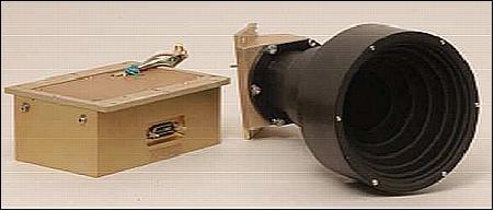
MSI (Multispectral Imager)
MSI is the primary onboard instrument for snapshot observations (in default mode) or in linescan mode (i.e. pushbroom mode). Observation in FMC (Forward Motion Compensation) mode other than 1:1 implies that continuous scanning is not possible. Hence, a snapshot MS image of 45 km x 45 km is obtained in the default scan mode (with an FMC of 4:1)
Linescan observation with FMC =1 is the same as FMC=4 as far as the imager operation is concerned except:
• The satellite body pitches during FMC4 imaging
• The clock speeds are adjusted to maintain square pixels.
The PAL (Phase Alternation Line) feature is intended for so-called 'viewfinding'. This gives the satellite operator an opportunity to view an area prior to imaging, instead of imaging blindly. An example would be to avoid cloud cover. By previewing the area the operator can steer the satellite clear of cloud to an adjacent area rather than imaging the cloud covered area.
The spectral bands were chosen to best suit agricultural applications e.g. crop planning, food security, water resource monitoring and also to support remote sensing applications such as disaster management, urban and environmental planning.
One of the functions of the onboard ADCS is to ensure accurate pointing and stabilization of the imager boresight towards selected targets on the ground. The high resolution imager has a swath of 52 km at nadir and scans the ground surface in multispectral bands using a FMC4 (Forward Motion Compensation) method, i.e. performing a pitch rotation while imaging, to slow down the ground scan velocity of the imager boresight and increase the integration time on the imager CCD arrays (Ref. 9).
Bands | Multispectral (linear), 6 bands |
Optics | Focal length = 0.4 m, aperture= 80 mm |
Spectral resolution | 440-510 nm (blue) Water bodies, soil/vegetation, deciduous/coniferous |
NER (Noise Equivalent Reflection) | < 0.6% with a forward motion compensation (FMC) factor of 4:1 |
MTF (Modulation Transfer Function) | ≥ 5% over the full field (excluding orbit motion effects) |
GSD (Ground Sample Distance) | 6.25 m @ an orbital altitude of 500 km |
Secondary detector function | Matrix detector (snapshot imaging) |
Data quantization | 12 bit (pixel storage of 2 bytes) |
Imaging modes | - Default scan mode with FMC = 4:1 (but system can operate with FMC = 1:1 with corresponding degradation in NER) - In FMC = 4:1 mode, non-contiguous scenes of 45 km x 45 km can be imaged (max 10 scenes before data downloading is required) - In FMC = 1:1 mode, a contiguous strip with 45 km swath can be imaged (max track length of 450 km can be imaged in 6 spectral bands before data downloading is required) |
Image data | At least 24 GByte of storage capacity for imagery, maximum 4 GByte for each of the 6 imager spectral bands, shared with the OBC for household functions. |
Viewfinder | - Live downlinking of PAL (Phase Alternation Line) video images during TT&C ground station passes. PAL TV images selectable between B&W (narrow FOV) and two wider FOV color PAL cameras - Viewfinder mode can be interrupted with either image snapshot or image linescan modes upon ground command |
An observation sequence with the MSI instrument is illustrated in Figure 14 involving the following steps (Ref. 9):
• Pitch forward ~ 13º, Roll = required amount for off-track image target
• Increase pitch rate to ~-0.6º/s
• Scan image for 34 s at constant rate for a 60 km image strip through target
• Stop at pitch ~ -13º
• Return to nadir pointing pitch & roll = 0º.
See also Figure 10.
Secondary Payloads on ZASat-002
The secondary payload complement involves experiments of South African academic communities funded mostly by the South African Space Program. The following experiments were selected to form part of the experimental payload on the spacecraft: SDR, VLF, ARECOTS, and FVSE. - To conserve mass and power, the secondary experiments were integrated into a single payload, together with the SA-AmSat voice repeater.
SDR (Software Defined Radio)
SDR is an experimental payload (digital radio) of the Digital Signal Processing & Telecommunications Research Group at Stellenbosch University (SU). The primary purpose of SDR is to be a proof-of-concept of using a reprogrammable radio in space applications. Further SDR experiments include: 23) 24)
• Demonstrating the use of direct-conversion transceivers in satellite communications
• Software compensation for non-idealities in the SDR front-end hardware
• Demonstrating the recommissioning of an SDR in a space application. The applications include:
- A voice beacon
- A voice transponder
- Digital telemetry transmitter
- AIS (Automatic Identification System) reception. Unfortunately, the SDR experiment cannot be used to receive real AIS transmissions at sea, since the radio front-end is not designed to receive in the 160 MHz band. At most, the instrument will demonstrate the use of the system by sending recorded AIS messages at 140 MHz, which lies within the receiver's range. The intend is to to lay down the groundwork for an AIS system in a future satellite.
Note: AIS (Automatic Identification System) is a shipboard broadcast system that continuously and autonomously broadcasts a ship's identification, position and other maritime navigational data. This data may be received by other ships in the vicinity, by a shore-based authority, or be collected by a satellite to monitor the marine traffic. Since July 2002, AIS is a mandatory system for sea-going vessels administered/enforced by the IMO (International Maritime Organization) - an automatic electronic reporting device i.e., a transponder fitted to a ship and operating in the VHF maritime band.
The SDR concept is particularly suitable to space applications, because communications systems on mobile platforms such as satellites can then be maintained and reconfigured using software updates, thus increasing the satellite lifetime. The satellite mission can then be changed by reconfiguring and upgrading the radio through software updates - a capability that is not possible with conventional hardware-defined radios.
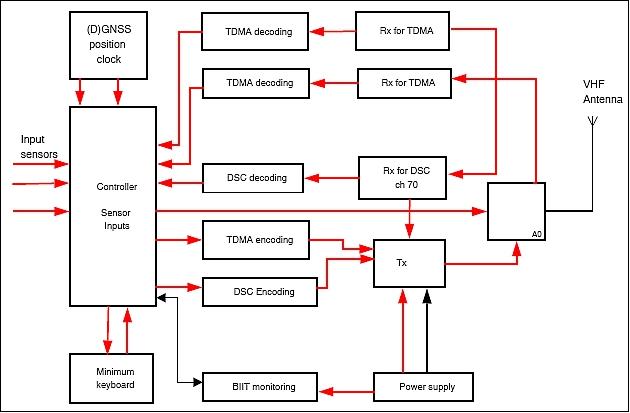
The satellite is equipped with an SDR receiver. Each ship is fitted with an AIS transponder, broadcasting AIS information in defined sequences. AIS uses a bit-oriented protocol for data transfer, which is based on the HDLC (High-level Data Link Control) standard, as specified by ISO/IEC 3309.
The ZASat-002 spacecraft receives the AIS signals on the VHF uplink. The AIS information is then stored and forwarded to the ground station using either the S-band channel or the UHF downlink provided by the spacecraft.
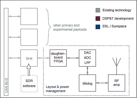
The SU design of the SDR onboard processor uses a GMSK modulator/demodulator. Demodulation, filtering, synchronization and signal recovery are all performed in software by the digital processor. The SDR architecture allows the development of a library of components that are used to build a radio system. A typical SDR component models a hardware component. The SDR components operate on the principle that all components receive, process and output streams of samples as shown in Figure 17, regardless of the number of input and output ports. The exact process function of each component is defined by the type of component being modeled..
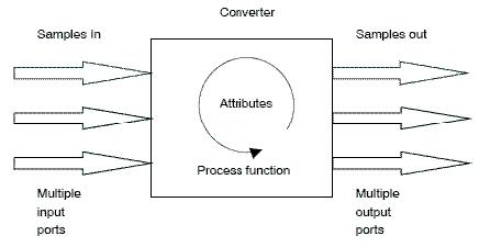
The SDR components are designed in such a way that they are reusable. Three basic functions are used as agents in each component to receive, process and dispatch samples between components. These functions are:
• A "read" agent that acquires samples from the component's input buffer
• A "virtual process" agent that specifies what process gets performed
• A "write" agent which dispatches samples to the input buffer of the next component.
VLF (Very Low Frequency)
The VLF radio electromagnetic experiment is provided by the University of KwaZulu-Natal, Durban, South Africa. The radio experiment consists of two work packages: the receiver hardware (provided by the University of Stellenbosch) and the software package development, provided by the University of KwaZulu-Natal. VLF is mainly comprised of three orthogonal magnetic loop antennas and a single electric dipole antenna. The data stream is sampled at 100 kHz; the digital data is then provided to the software backend. The current goal is in the analysis of the broadband data, looking for:
• Phenomena such as chorus and whistlers, which are produced by natural processes on Earth (lightning) and in space (wave-particle interactions)
• Detection of signals from terrestrial VLF transmitters which broadcast phase-stable narrowband signals at frequencies around 20 kHz.
The broadband data is being processed onboard by generating dynamic spectra. This onboard data handling results in a significant compression effect of the data volume; the resulting spectral data is transmitted to the ground station. The University of KwaZulu-Natal is providing the VLF data analysis during the mission.
ARECOTS (Architectural Radiation Experiment for Commercial Off-the-Shelf) devices, provided by Stellenbosch University.
FVSE (Forced Vibration String Experiment) provided by the Nelson Mandela Metropolitan University.
SA AMSAT (South Africa Amateur Radio Transponder and Digipeater)
SA AMSAT is a 2 m/ 0.70 m (VHF/UHF) amateur radio system provided by SA AMSAT (South Africa AMSAT). This payload shares the VHF receiver and UHF transmitter used by the SDR project. SA AMSAT has designed and built a control system to facilitate the following operations: 25) 26)
• VHF/UHF voice transponder with an uplink in the 2 m band and a downlink in the 70 cm band
• A parrot repeater (voice digipeater)
• A voice beacon.
The control unit will command the various functions of the transponder and handle the parrot and beacon messaging. On receipt of a tone from the VUCU VHF receiver, the CTCSS (Continuous Tone Coded Squelch System) signal will be decoded and, depending on the tone received, the unit will command the VHF/UHF transponder operation or the parrot repeater. In the transponder mode, the satellite will act like a cross-band FM repeater and allow two way communications with other stations on the ground.
If the tone received indicates parrot operation, the interface unit will record 20 seconds of audio on its VHF uplink receiver and replay the recorded audio on the UHF downlink. Should, for a predetermined period, there be no tones received, the controller will initiate a voice beacon, transmitting a pre-recorded message at regular intervals. This facility will offer many opportunities for educational projects.
Ground Segment
Ground Stations
• ESL (Electronic Systems Laboratory) Stellenbosch ground station. SunSpace spacecraft control from launch to the end of the commissioning phase.
• Hartebeetshoek ground station of SAC near Pretoria for spacecraft operations and data downloads.
The owner of the satellite, the DST (Department of Science and Technology) of the South African government, requested that spacecraft operations be transferred to the SAC (Satellite Applications Centre), a division of the Council of Scientific and Industrial Research (CSIR), after the commissioning phase (a six-month period) was completed. This necessitated the transfer of (some) design authority knowledge to operators who had never before operated a satellite, but who have a lot of experience in data capture and processing. 27)
This required a rethinking of the more conventional approach where a clear division exists between a mission operations system, a payload operations and data system, and a ground station system. With SumbandilaSat, the traditional boundaries between these entities became fused and required careful planning and management. In retrospect, this approach had the added benefit of shared resources and therefore improved utilization of the mission assets.
The new SumbandilaSat operations team of SAC had no prior satellite experience.
MCS (Mission Control System)
The MCS of SunSpace was developed in parallel with the satellite and is based on the following premises:
• Reusability of the MCS for future SunSpace (and other) missions.
• High-level, intelligent Flight Control Procedures (FCPs) are run on the satellite. The FCPs used are based on the Lua scripting language.
• A fully functional operating system is implemented on the satellite OBC in order to support the previous requirement. QNX was chosen for this purpose, running on an SH4-based processor.
• Much of the satellite complexity is obscured for the operators, who use the MCS to interact with the satellite. No SAC operator had prior satellite experience.
• A distributed MCS architecture is supported.
• The FCT (Flight Control Team) comprises satellite operators and mission specialists, from both the SAC and SunSpace, being a mixture of inexperienced and senior personnel.
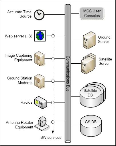
The MCS consists of a central database with distributed clients. Clients can be services responsible for managing a particular piece of ground station hardware or it can be consoles that provide a user interface to the MCS functions. In addition, there are several servers connected via the backbone network.
The MCS has three primary functions, implemented as 13 distinct consoles:
1) Allows planning of future satellite activities
2) Manages satellite interaction during overpasses
3) Decodes, archives and provides access to satellite telemetry and status information retrieved during overpasses (data analysis).
A logical representation of a deployed MCS is shown in Figure 19. Such an installation can service multiple satellites from geographically distributed ground stations, provided each satellite has its own DB and Satellite Server instance.
For the operational phase of the SumbandilaSat mission, the MCS is deployed as shown in Figure 20. The following should be noted:
• The two primary facilities (SU and SAC) are linked via a secure IPSec tunnel that runs over the 10 Gbit/s SANReN infrastructure (a high-bandwidth fiber network that links over 200 research institutions in 7 South African metropoles). The transport lag over this link is less than 15 ms which does not hamper inter-console MCS communications.
• Commissioning was done only from the Stellenbosch part of the installation. Thereafter (starting in March 2010), the mission DB was transferred to SAC. The transition was completed smoothly between the morning and evening groups of passes in one day!
• Via a VPN (Virtual Private Network), the system also allows MCS consoles to run on any remote PC, over a normal internet connection. This method is rarely used for real-time interaction with the satellite, but provides convenient connectivity to the mission DB, especially for "off-line" data analysis.
• The MES (Mission Exploitation System) is separate from the rest of the SumbandilaSat mission set-up and forms part of the existing SAC infrastructure and services.
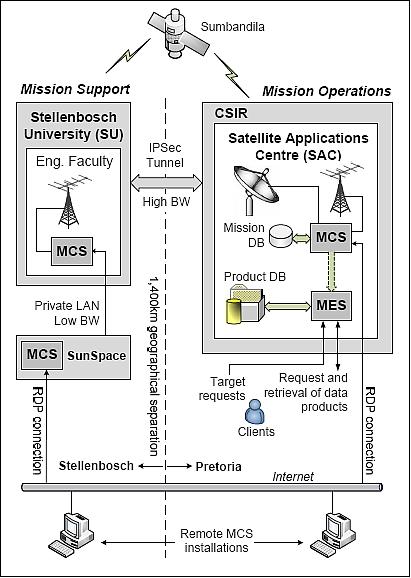
The MCS supports a smooth transition from one GS (Ground Segment) element to another, even during an overpass. For example: SumbandilaSat can be tracked / commanded from SAC as the satellite passes over the ground station from North to South. In less than 5 s of the satellite footprint leaving the SAC ground station, the antenna at the SU, located 8º further South, can take over from SAC, thus extending the contact time with the satellite.
The communications link, set-up between the SU and SAC stations, took some time to stabilize due to protocol and hardware problems, but once in place it proved that the MCS can work reliably in a distributed deployment scenario, provided the transportation lag can be limited to 50 ms. For future missions such as the ARMC (African Resource Management Constellation), this will become a central feature.
Request and retrieval of data products: Two methods of communication are used in the MCS: point-to-point client-server communication and communication on a message bus. Point-to-point communication is used for commanding, e.g. to instruct an antenna controller to start tracking. The message bus provides a publish/subscribe mechanism where clients subscribe to topics in order to receive information published on it by others. Typical information published on the message bus are current log entries and system state information such as current satellite position.
In retrospect, the SumbandilaSat project turned out to be a mission of many firsts:
• First national satellite
• First opportunity for SAC to operate a satellite
• First opportunity to put the newly developed MCS architecture to test
• First time in SunSpace's history where the day-to-day health monitoring of a satellite had to be transferred to an entity which is not the design authority
• First time that remote sensing data products from a local source had to be integrated with historical non-African sources in the MES (Mission Exploitation System) of SAC.
It is expected, that SAC and SunSpace will be integrated eventually into the structure of the newly created South African National Space Agency (SANSA).
References
1) A. Schoonwinkel, H. Burger, S. Mostert, "Integrated Hyperspectral, Multispectral and Video Imager for Microsatellites," Proceedings of the 19th Annual AIAA/USU Small Satellite Conference, Logan, UT, Aug. 8-11, 2005, SSC05-IX-6
2) S. Mostert, J. du Plessis, "Earth Observation - A New Paradigm," 5th IAA Symposium on Small Satellites for Earth Observation, Berlin, Germany, April 4-8, 2005
3) A. Schoonwinkel, G. W. Milne, S. Mostert, "Opportunities in Satellite Based Earth Observation, Telecommunication and Navigation for Sustainable Development in Southern Africa." Acta Astronautica, Vol. 53, 2003, pp. 749-759
5) S. Mostert, J. Roodt, "A Remote Sensing Roadmap for Developing Countries," Proceedings of the 57th IAC/IAF/IAA (International Astronautical Congress), Valencia, Spain, Oct. 2-6, 2006, IAC-06-B5.1.03
6) H. Roodt, J. Steyn, "Mechanical Structural Development of SumbandilaSAT, SA's first National Satellite," Proceedings of IAC 2011 (62nd International Astronautical Congress), Cape Town, South Africa, Oct. 3-7, 2011, paper: IAC-11-C2.1.5
7) Press Release of the South African Government of July 31, 2006. Information provided by Martin Jacobs of SunSpace Ltd., Stellenbosch, South Africa
8) S. Mostert, "Impact of SumbandilaSat on Sustainable Development in context of African Resource Management Constellation," UN Workshop 'Use of Space Technology for Sustainable Development, ' April 25-27, 2007, Rabat, Morocco, URL: http://www.unoosa.org/pdf/sap/2007/morocco/presentations/4-12.pdf
9) Willem H. Steyn, "In-Orbit AODCS Performance of SumbandilaSat an Earth Observation Satellite for South Africa," Proceedings of the 61st IAC (International Astronautical Congress), Prague, Czech Republic, Sept. 27-Oct. 1, 2010, IAC-10.B4.6A.4
10) Willem H. Steyn, "An Attitude Control System for SumbandilaSat - an Earth Observation Satellite," Proceedings of the IAA Symposium on Small Satellite Systems and Services (4S), Rhodes, Greece, May 26-30, 2008, ESA SP-660, August 2008
11) Daniël van der Merwe, Johannes Steyn, "Mechanical Thermal Development of SumbandilaSat, SA's first National Satellite," Proceedings of IAC 2011 (62nd International Astronautical Congress), Cape Town, South Africa, Oct. 3-7, 2011, paper: IAC-11-C2.1.6
12) http://orbiter-forum.com/showthread.php?p=120297#post120297
13) http://www.russianspaceweb.com/meteor.html
14) Keith Campbell, "Russia keen to increase space collaboration with South Africa," Aug. 14, 2009, URL: http://www.engineeringnews.co.za/article/russia-would-like-to-increase-space-cooperation-with-south-africa-2009-08-14
15) Information provided by Jan-Albert Koekemoer of SunSpace, Stellenbosch, South Africa (Feb. 27, 2012)
16) Guy Martin, "SumbandilaSat beyond repair," Jan. 25, 2012, URL: http://www.defenceweb.co.za/index.php?option=com_content&view=article&id=22870:sumbandilasat-beyond-repair&catid=90:science-a-technology&Itemid=204
17) Khalid Manjoo, Gladys Magagula, "SumbandilaSat - Leading the way for future satellite programs," Proceedings of IAC 2011 (62nd International Astronautical Congress), Cape Town, South Africa, Oct. 3-7, 2011, paper: IAC-11-B4.1.2
18) Chris Stein. "South Africa: Satellite Preparing Scientists for New Space Industry," October 14, 2010, URL: http://allafrica.com/stories/201010140974.html
19) Information was provided by W. H. (Herman) Steyn of SunSpace / Stellenbosch University, South Africa
20) http://sumbandilamission.blogspot.com/
21) Maeve Hickok, "SumbandilaSat EO satellite shows South Africa's Space Mettle," Jan. 11, 2010, URL: http://www.earthzine.org/2010/01/11/sumbandilasat-eo-satellite-shows-south-africa%E2%80%99s-space-mettle/
22) http://sumbandilamission.blogspot.com/2010/02/gps-commissioned.html
23) K. F. Mathapo, G.-J. van Rooyen, "A Software Defined Radio AIS for the ZA-002 Satellite," Proceedings of the 20th Annual AIAA/USU Conference on Small Satellites, Logan, UT, Aug. 14-17, 2006, paper: SSC06-V-3
24) G-J van Rooyen, "Software-Defined Radio," March 16, 2006, URL: https://web.archive.org/web/20060615040325/http://amsatsa.org.za:80/intecnet_sdr.pdf
25) https://web.archive.org/web/20120114174906/http://www.amsatsa.org.za/SZASAT.htm
26) Information provided by Hans van de Groenendaal, SA AMSAT
27) Jan A. Koekemoer, "SumbandilaSat Operations - A Cooperative Approach,"Proceedings of the 61st IAC (International Astronautical Congress), Prague, Czech Republic, Sept. 27-Oct. 1, 2010, IAC-10.B6.2.8
The information compiled and edited in this article was provided by Herbert J. Kramer from his documentation of: "Observation of the Earth and Its Environment: Survey of Missions and Sensors" (Springer Verlag) as well as many other sources after the publication of the 4th edition in 2002. - Comments and corrections to this article are always welcome for further updates (eoportal@symbios.space).