STRV-1 (Space Technology Research Vehicle 1) Missions
Non-EO
Mission complete
UK (Dstl)
Quick facts
Overview
| Mission type | Non-EO |
| Agency | UK (Dstl) |
| Mission status | Mission complete |
| Launch date | 17 Jun 1994 |
| End of life date | 2001 |
STRV-1 (Space Technology Research Vehicle 1) Missions
STRV is a multi-microsatellite cooperative technology program, initiated by DERA (Defence Evaluation and Research Agency, Farnborough, UK) in 1992. The prime objective of the program is to provide opportunities for the evaluation of several new technologies in-orbit.
Note: as of July 2 2001, DERA separated into two organizations:
• A new independent science and technology company called QinetiQ
• DSTL (Defense Science and Technology Laboratory) an agency of the UK Ministry of Defense (MoD).
The spacecraft were designed, built, and tested at DERA (with assistance as required from subcontractors) and were operated (1994-1996) from a ground station facility at DERA Lasham in Southern England. The short duration time scale of the project (from design phase to operations in 3 years) has guaranteed the return of experimental data in a meaningful time frame. The first two S/C of the mission were launched in June 1994. Two more microsatellites were launched on Nov. 16, 2000. 1) 2) 3) 4) 5) 6) 7)
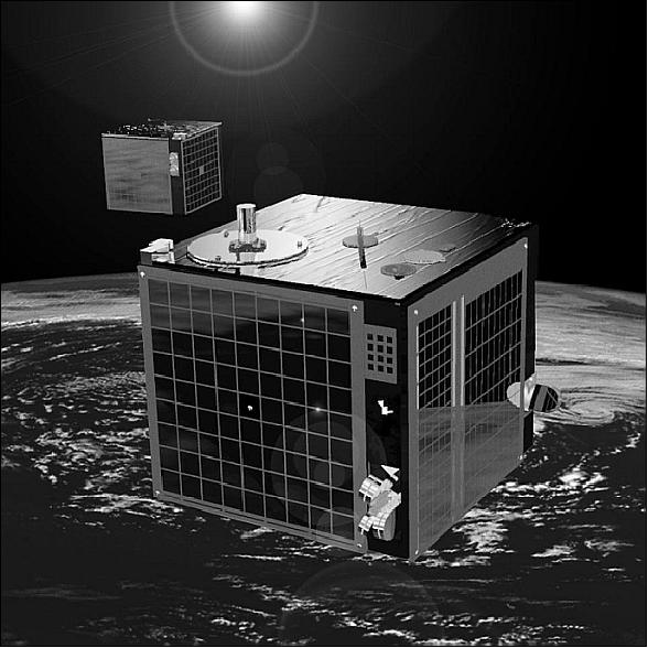
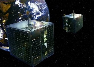
STRV-1a and -1b Spacecraft
STRV-1a and -1b were two microsatellites of DERA (funding by MoD) at Farnborough, UK (with contributions from: ESA, BMDO (Ballistic Missile Defense Organization)/JPL, USAF/PL, universities, SSTL). The objective was to evaluate new technologies in the high radiation dose environment of GTO (Geosynchronous Transfer Orbit) - test of advanced structural materials, radiation hardened computers, sensors, solar cells, vibration suppression on a cryogenic cooler, measurements of the ion and electron environment, spacecraft charging, and microelectronics.
Both spacecraft were cubical in shape based on carbon/PEEK thermoplastic skinned aluminum honeycomb panels. The satellites were spin-stabilized at about 5 rpm (magnetorquer attitude control and cold gas thruster system, attitude sensing with Earth and sun sensors). The GaAs solar panels (4) were body-mounted. They provided 33 W (BOL) of DC power to a 28V power distribution bus. In addition, there were 16 NiCd cells providing 46 Whr of power storage. Onboard data handling used a GEC Plessey MIL-STD-1750 compatible processor employing radiation tolerant SOS technology. The S/C mass was nominally 52 kg and the S/C design life was one year. Prime contractor for the design and manufacture of the microsatellites was the Aerospace Division of DRA (Defense Research Agency), Farnborough, UK. 8) 9)
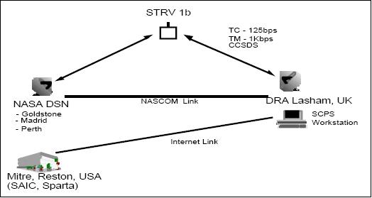
The RF communications system conformed to ESA standards using dual redundant transmitters/receivers at S-band. The data transmission (uplink rate: 125 bit/s, 2.025-2.12 GHz, and downlink rate: 1 kbit/s, 2.2-2.3 GHz) used the CCSDS packet TM/TC concept implementation of ESA with custom chip sets.
Launch
The launch of STRV-1A and -1b took place on June 17, 1994 from Kourou, French Guiana. They were launched as secondary payloads on ASAP (Ariane Structure for Auxiliary Payloads) on Ariane-4 flight V64. The primary payload on this flight was Intelsat 702. The two STRV microsatellites were placed into orbit 25 minutes after lift-off. Note: the STRV-1a and -1b launch was the first occasion that the Ariane-4 had launched auxiliary payloads into Geostationary Transfer Orbit (GTO).
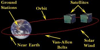
Orbit
Elliptical GTO orbit, perigee = 280 km, apogee = 35,818 km, inclination = 7.3º, period = 10 hours and 27 minutes. The orbit crossed the Van Allen Belts each orbit with a maximum of ionization radiation seen in near-Earth orbit: it suffered electrostatic charges close to apogee, and atomic oxygen erosion at perigee. This orbit was extremely interesting for measuring the Earth's radiation environment, since it provided full exposure to the trapped radiation belts as well as cosmic rays and solar energetic particles.
Note: During the initial orbital period, up to about the end of August 1994, STRV-1a experienced in-flight anomalies (low power due to failure of at least one battery cell) resulting in a delay for some experiment operation until September 1994.
Despite the very high radiation dose received by the platform systems during the mission, the majority have performed exceptionally well. With one or two small exceptions, the spacecraft electronics were built entirely from military specification components. Although only one receiver on each spacecraft remained usable, the redundancy philosophy adopted has prevented the termination of the mission.
Parameter | STRV-1a | STRV-1b |
Total mass | 52 kg | 54 kg |
S/C dimensions | 440 mm x 440 mm x 420 mm | |
S/C structure | Carbon/PEEK thermoplastic skinned Al honeycomb | |
S/C thermal control | Passive | |
Power generation and storage | Four body-mounted GaAs solar panels, 46 Whr NiCd battery | |
S/C power (at start of mission) | 31 W (at 28 V) | 33 W (at 28 V) |
Power available to payload | 19 W (average), 120 W (peak) | |
Stabilization | Spin at 5 rpm (provided by the launcher at separation) | |
Attitude sensing subsystem | V-slit sun/Earth sensors and analog sun sensors | |
Attitude control subsystem (ACS) | Magnetorquer coils & cold gas thruster | Magnetotorquer coils |
Onboard computer (OBC) | Dual-redundant GEC/Plessey Mil Std SOS 1750a microprocessor | |
Memory | Dual-redundant 128 kBytes SOS RAM, 64 kBytes ROM | |
Communications | ESA packet TM/TC CCSDS standard, 12 m antenna at DERA Lasham ground station (26 m DSN antennas) | |
Mission Status
Mission operations were performed from the DERA/Lasham ground station (southern England) and the NASA Deep Space Network (DSN) from June 1994 to June 1996, when routine orbital maintenance of the S/C was passed to LASP (Laboratory of Atmospheric and Space Physics) at the University of Colorado, CO, USA. LASP used the S/C for communication experiments.
Although designed for only one year of operations, both satellites continued for a total of 4 years in the harsh environment of GTO before the program partners decided to shut them down. STRV-1a was turned off in March 1998, and STRV-1b was turned off in September 1998. Among their notable achievements was the first demonstration of a tactical cryo-cooler in space and a comprehensive mapping of the electron and proton fluxes in the Van Allen Radiation Belts.
STRV-1a Sensor/Experiment Complement
AOE (Atomic Oxygen Experiment), provided by DERA and the University of Southampton. Objective: Measurement of atomic oxygen (AO) by silver loss determination in different material specimens - consideration as a future monitoring method of AO environments. AOE is comprised of twelve silver resistance sensors. As silver is converted to its non-conducting oxide the resistance increases. This increase can be measured and converted into silver loss. The erosion resistance of test materials is measured by coating the thin silver films with overlays of the test material. When this coating is breached the silver starts to oxidize, a resistance increase is observed. Knowledge of the fluence experienced and the thickness of the coating enables calculation of the erosion rate. Silver sensors coated with polyethylene, PTFE, carbon, and silica were flown. 10) 11)
BRE (Battery Recharge Experiment), provided by ESA/ESTEC. Objective: Demonstration of control techniques using conventional constant current battery charging, followed by current tapering, instead of simple voltage level triggered end-of-charge cut-off for LEO S/C. Selection of an end-of-charge voltage level to avoid both undercharge and overcharge throughout the lifetime of the S/C.
The basic problem was selecting an end-of-charge voltage level which would avoid both battery undercharge and overcharge throughout the S/C lifetime. BRE was activated in September 1994. The results of the test have implications for S/C power subsystem designers.
CAE (Charge Alleviation Experiment) provided by DERA. Objectives: 1) Demonstration of an active S/C surface charge alleviation system, and 2) Test of several new technologies in orbit, in particular the effects of operation of other S/C subsystems such as that of an ion propulsion system (UK-10 hollow cathode) and that of a cold gas ACS (Attitude Control Subsystem) on the bulk and differential charging of surface materials. 12)
The CAE system is comprised of the following components: (total mass = 3.25 kg, power = 30W during steady-state operation, power = 80 W for initial heater operation of about 30 s).
• Fill and drain valve
• Xenon storage tank
• Five standard series 107 solenoid valves
• Miniature tank pressure transducer
• Plenum tank (100 cm3)
• Miniature plenum tank pressure transducer
• Plenum tank orifice
• Spin-up thrusters and associated pipe work
• UK-10 ion thruster hollow cathode
• Two DC-to-DC power supplies and associated electronics
• Interconnecting pipe work and weld fittings.
The CAE system relies on the ability to produce a diffuse cold plasma of inert xenon gas around the S/C thereby neutralizing the high differential surface potentials. In the CAE design, the diffuse plasma envelope is provided (produced) by the operation of three subexperiments with objectives of their own.
• First flight test of the UK-10 ion thruster hollow cathode assembly.
• First flight test of the xenon gas flow control system, developed for the UK-10 IPS (Ion Propulsion System), with associated solenoid valves, orifices, and valve actuating electronics.
• The provision of a cold gas attitude control subsystem (ACS), a backup for the magnetorquers for control of S/C precession.
SCDE (Surface Charge Detector Experiment) provided by DERA. Objective: Non-contact measurement of surface potentials. The Pockels effect technique (an electro-optical method) was chosen which relies on special crystal properties. The experiment collects charge on a piece of kapton (an insulator) which is exposed to the space environment. Sensing crystals are placed under the kapton, one of the crystals is shielded from electric fields by a thin piece of foil (the monitor). A plane-polarized laser beam is passed through each crystal and analyzed (the strength of the electric field is deduced from the polarization state). The monitor crystal does not respond to the electric field, thus providing a reference. SCDE had a mass of 0.6 kg, power of 2 W, and dimensions of about 100 mm x 150 mm x 30 mm.
CID (Cold Ion Detector). A UCL/MSSL (University College London/Mullard Space Science Laboratory) instrument with the objective to measure the energy spectrum of incident, low-energy ions in the interplanetary plasma. A further objective of CID is to act as a diagnostic tool - to directly sense the cold ions produced by the CAE neutralizer. CID is an electrostatic deflection differential energy analyzer consisting of the following elements:
• A collimator accepting a beam of conical shape with a half angle of 5.7º
• An electrostatic energy analyzer with a passband of DE/E = 0.14
• A microchannel plate detector which records the impact of the particles.
The CID instrument pointed perpendicular to the spin axis of the S/C, protruding some 70 mm from the surface. The CID used a radical new cylindrical design which enabled the complex instrumentation to be housed inside an easy-to-mount metal cylinder. The entire detector measured 120 mm in length with a mass of 180 g (less than a quarter of the mass of previous detectors). The 2 mm of Alu shielding gave the instrument a minimum energy threshold of approximately 750 keV.
LPE (Langmuir Probe Experiment), provided by DERA. Objective: Xenon plasma diagnostic instrument for CAE. A conducting surface is biased with a sweeping voltage, attracting either positive ions or electrons, which are measured as a current in the experiments electronics. The LPE consists of a conducting planar probe of 20 mm diameter with a surrounding guard ring of 100 mm diameter. In the presence of plasma a sheath forms over the conducting surface. LPE was mounted close to neutralizer cathode in order to measure the local electron temperature, electron number density and plasma potential.
CREDO-II (Cosmic Radiation Environment and Dosimetry Experiment). A DERA/UKAEA (United Kingdom Atomic Energy Authority) experiment with the objective to characterize the radiation dose received by the spacecraft [ a) total dose, b) cosmic ray and solar heavy ions, c) protons trapped in the Van Allen belts]. The instrument is the latest of an evolving series which have flown on aircraft [the Concorde (BA) and Boeing-767 (SAS)], on the Shuttle (STS-48, -44, -53, -56, -68, and -63), in sun-synchronous orbit (UoSat-3, since Jan. 23, 1990), and on the USAF APEX satellite (orbit: 359 km x 2544 km, 70º inclination). 13)
CREDO employs a telescope technique to detect coincidences between parallel planes of p-i-n (p-intrinsic-n) diodes to provide directional information and to define the pathlength of particles through the diodes to within 29%. The square diodes (each with a path length of 200 μm, area of 10 mm x 10 mm) are configured in two orthogonal arrays with their axes aligned with two S/C axes. Pairs of diodes are placed in a telescope arrangement with a separation of 1.75 mm, each array consists of four such pairs. - The upper and lower arrays of each telescope system are connected via separate charge amplifier systems into hardware discriminators with thresholds close to 0.33 pC (7.4 MeV) of charge deposited per event. Events are coincident when both discriminator thresholds are exceeded within a 10 μs gate time. Upon sensing a coincident event, the CREDO-II micro-controller performs pulse-height analysis upon the output of one of the planes of each telescope. Fifteen channels of pulse-height analysis are provided. The telescope system does not respond to particles arriving with oblique angles of incidence. Only ions are detected by this arrangement. - Total dose is measured at three locations within the CREDO box using radFET dosimeters. These are MOSFET devices are designed to trap positive charges and shift the threshold voltage of the radFET. Each radFET is co-located with a temperature sensor to permit temperature correction of voltage shift. - Non-coincident events detected by the telescope system are processed similarly, but separately from the coincident events. The detector arrangement is sensitive to protons which can deposit sufficient energy via ionization along oblique paths through the diodes.
RDRS (Radiation Dose Rate Sensor), provided by DERA. Objective: Monitoring of gamma ray bursts.
STRV-1b Sensor/Experiment Complement
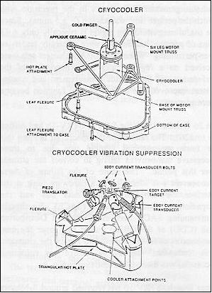
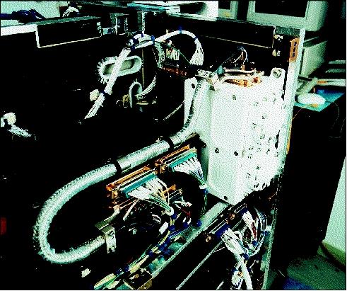
CVSE (Cryocooler Vibration Suppression Experiment), provided by BMDO and managed by JPL. Objective: To demonstrate and to qualify a new vibration suppressing design by employing piezo materials. (Cryocoolers are used to cool IR or CCD detectors to lower the thermal noise threshold. Since Stirling coolers have a mechanical compressor, there is a significant vibration problem introduced by the cooling of optical instruments). The intent is to use these low-power flight piezo drivers and control systems in zero-g environments. 14)
To meet stringent power, weight, and space constraints, the experiment makes use of the tiny 0.2 watt 80 K tactical Stirling coolers (of Texas Instruments). Two different vibration-cancellation actuator techniques are being demonstrated: 1) applique ceramic piezoelectric actuators that are bonded to the coldfinger and stretch the coldfinger to cancel tip motion, and 2) commercial low voltage piezoelectric translators that similarly cancel tip motion by moving the entire cryocooler in three axes. Motion of the coldfinger tip is measured in all three axes to 10 nm accuracy using eddy-current transducers. Two types of control systems are also being demonstrated: 1) an analog control system that uses a bandpass filter to track the drive signal and suppress it, and 2) a unique narrow-band adaptive feed-forward system that continually updates a steady-state command signal to each actuator to cancel the tip vibration. Either control system can be used with either actuator.
Using the cryocooler as a vibration source, the response of the satellite was determined from accelerometer data. The translators with digital control reduced the vibration by a factor of about 75. 15)
SEE (Space Environmental Effects) experiments. The overall objective is to measure and evaluate the effects of the high radiation environment on electronic devices. The device sets tested are:
- Neural network integrated circuits
- HIP (Heterojunction Internal Photoemission) infrared sensors
- CMOS (Complementary Metal-Oxide Semiconductor) radiation and SEU (Single Event Upset) monitors
Two identical sets of devices are used, one with minimal shielding to radiation in the spin axis of the S/C, and the other set with significant shielding to provide a basis for comparison. Unfortunately, SEE data were only obtained up to early October 1994 when a system failure occurred.
• NNE (Neural Networks Experiment). Objectives: To demonstrate fault-tolerant and graceful degradation characteristics of analog neural network VLSI chips (JPL) in the space environment. For NNE, a special feed-forward “learning” architecture was chosen (signal flow from one layer of neurons to the next through a connecting mesh of synaptic weights) with a suitable pattern recognition problem as a bench-mark for learning.
• HIP (Heterojunction Internal Photoemission) Infrared Sensors. The objective of this experiment is to determine if exposure of the HIP sensor to the complex spectrum of incident radiation might result in increased sensitivity. - The experiment measures the dark current to obtain an indication of the radiation damage to the specimen.
• SEU (Single Event Upset)/RADMON (Radiation Monitor) Experiment. Objective: To develop a small, low-cost, low-power SEU and TD (Total Dose) RADMON using standard CMOS processes. RADMON consists of 16 SRAMs (4-kbit each) designed to detect protons, alpha particles, and heavy ions (SEU-SRAMs). In addition, RADMON contains four p-FETs for detecting total dose (TD-FETs). The SEU-SRAMs and TD-FETs are shielded behind primary and control shields.
REM (Radiation Environment Monitor) provided by ESA. Objectives: To study the GTO radiation environment, its spatial, temporal and directional variability for the development of improved models. The results are intended to be used in the design of electronic components for future S/C.
REM consists of two independent shielded silicon detectors (and charge-sensitive amplifiers) with different types of shielding. Energetic particles impacting on the detectors generate pulses which are counted. Each REM detector (300 Tm silicon diode detectors) has 16 channels for pulse magnitude discrimination. The `electron detector' is 25 mm2 in surface area with a 3 mm Al shield; the `photon detector' has a surface area of 150 mm2, it is shielded by 3 mm Al and an additional 0.75 mm of tantalum. The instrument accumulates energy deposit spectra over varying integration periods, adapted to the speed of the spacecraft and the available on-board memory. These energy deposits can be converted fairly easily into total absorbed dose. REM has a mass of 3 kg, a power consumption of 5 W, and a data output of 20 kByte/orbit. 16) 17)
SCTE (Solar Cell Technology Experiment). The objective is to measure the current/voltage characteristics of many new or improved types of solar cells. A total of 47 cell types are exposed to the radiation environment and operated whenever the sun direction is within 5º of the normal to the panel.
SCPS (Space Communications Protocol Standards), provided by USAF, NASA/JPL, MoD, DERA. Objectives: To demonstrate and test a full space implementation of the Space Communications Protocol Standards. To provide a more comprehensive set of spacecraft control and monitor data handling services based on and compatible with commercial Internet protocols but adapted to the specific needs of space communications links. These will serve a wide range of civil and military space missions for the foreseeable future. The applications of SCPS to space based communications links, supporting Internet type data transfers, particularly those involving longer time delays, is also being investigated. 18)
Although the CCSDS packetized standards provide the underpinning for the automated, error-free exchange of data between space and ground stations, it is limited to basic data transfer. SCPS will provide the additional capability to aggregate both telecommand and telemetry data into recognizable files and transport them end-to-end through the data networks containing space links in a reliable and secure manner. To do this, a “skinny stack” of upper layer space data protocols are being developed which will eliminate the need for “project uniqueness” and provide:
• An efficient file handling protocols based on FTP
• A retransmission control protocol based on TCP with various modes of operation and for use over networks with one or more unreliable space data transmission paths
• An optional data protection mechanism which can assure end-to-end security and integrity of message exchange
• A scalable networking protocol to support both connectionless and connection oriented message routing through networks with space data transmission paths.
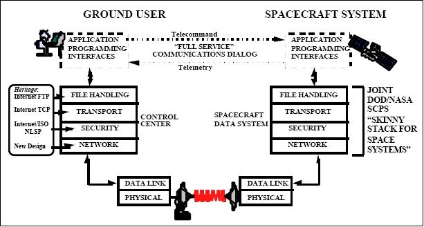
The STRV spacecraft were the first in Europe to fully implement the CCSDS compatible ESA TT&C standards in an operational mission and are expected to have widespread international application in the space industry. Together with the reprogrammable onboard computers, the spacecraft therefore provided an excellent vehicle to prove the SCPS protocols over a live space link. New SCPS software was hosted on one of the STRV-1b spacecraft Mil Std 1750A, (dual-redundant) computers with 128 kByte SOS RAM. The SCPS development team produced a “lightweight” version of the Transport, File Transfer and Security protocols which were compiled into 1750 assembler code and debugged using an STRV engineering model. After debugging, the software was uploaded to STRV-1b with the assistance of an operating system (kernel), developed by the Mitre Corporation to provide the interface to the onboard computer, taking up 120 kByte of the available RAM.
Modifications to the ground station were also necessary. Two 486 PCs were added to the original configuration: one for secondary CCSDS processing and one, the SCPS workstation, to host the SCPS ground protocol software. The general arrangement is shown in Figure 6 which shows the alternative links through Lasham or the DSN to the spacecraft and the NASCOM link between Lasham and Goldstone. Additionally, an Internet link with Mitre in Reston VA enabled the trials to be supervised remotely from the USA.
The SCPS software runs as an application on the SCPS workstation. It receives instructions from the Internet and forwards them, using the SCPS protocols, to a telecommand workstation which transmits them as STRV CCSDS packets to the spacecraft. Software in the spacecraft monitors the received instructions and provides performance feedback through the telemetry downlink. As a part of this experiment, STRV-1b was given by NASA/JPL its own Internet Protocol (IP) address. In 1996, this represents the first spacecraft to do so, and to demonstrate that instructions could be sent by Internet from remote sites to an operational spacecraft.
The experiment has provided a very useful checkout of basic elements of the SCPS protocols over a live space link. Full data analysis will take until the end of 1996 but the initial results are already providing a useful input to the development of the full standards. It also demonstrated the benefits of the capability to reprogram an in-orbit computer to change mission characteristics at short notice and low cost.
STRV-1c and -1d Spacecraft
These were DERA follow-up microsatellite technology missions based on the STRV-1a & -b design (they incorporate a sample `multi-function structure' designed to achieve significant savings in future spacecraft mass and cost). The overall objectives were to demonstrate emerging technologies on the premise of `faster, better, cheaper' in a collaborative environment of participating institutions. A particular objective was to enhance the capabilities of future communications, navigation, and surveillance systems. 19) 20)
The S/C of STRV-1c/-1d were larger (more mass) than those of STRV-1a/-1b to accommodate more experiments (otherwise same architecture). The only significant enhancement was the introduction of full dual-redundancy throughout all the platform subsystems. 21) 22)
The spacecraft “firsts” include:
• Power from an operational, rechargeable lithium ion battery
• Use of a 'radiation-hardened' version of the powerful Sun Sparc microprocessor
• Use of a novel DERA-patented carbon-composite joint in the spacecraft structure
• Demonstration of secure communications through data encryption
• Demonstration of new Internet-based space communications standards that may be suitable for future missions such as a Mars orbiter/lander
• Comprehensive mapping of the GPS (Global Positioning System) signal environment at altitudes out to geosynchronous orbit (35,900 km)
• Evaluation of new infra-red detector technology.
S/C total mass, power | 100 kg, 65 W (BOL), GaAs solar cells |
S/C size | Cube with 700 mm length of each side |
Payload mass | 25 kg |
Battery | Li-ion (rechargeable) |
Power bus | Regulated 28V ± 2% |
Computers | Military specification 31750a (dual-redundant silicon-on-sapphire) |
Platform memory | 2 MByte per computer (dual-redundant Military Specification RAM) |
Communications | ESA CCSDS Packet TM & TC (with optional encryption on STRV 1d) |
Attitude control | Spin stabilized control to ± 3º. Magnetorquer & cold gas precession thruster maneuvers |
Nominal attitude | Sun aspect angle = 90º ± 10º & orbit normal ± 10º |
Launch
A simultaneous ASAP (Ariane Structure for Auxiliary Payloads) launch of both STRV spacecraft took place on Nov. 16 2000 on an Ariane-5 launch vehicle from Kourou. The STRV satellites and the AMSAT Phase 3-D (OSCAR 40) satellite were secondary payloads to the PAS-1R (PanAmSat-1R) communications satellite. 23)
Orbit
Elliptical GTO (Geosynchronous Transfer Orbit), perigee = 620 km, apogee = 36,000 km, inclination = 7.5º, orbital period of about 10.5 hours.
Mission Status of STRV-1c and -1d
After two weeks of successfully commissioning all subsystems and experiments on both spacecraft, and immediately prior to announcing the start of routine operations, telemetry from both spacecraft indicated a serious problem. Neither spacecraft would respond to commands from the ground. Telemetry from both spacecraft indicated that power had been cut to the receivers. Subsequent ground investigation confirmed the telemetry message and the root cause of the mishap. The unrecoverable problem with the spacecraft receivers caused the end of the mission
Both spacecraft were formally declared lost after 6 months of observations and attempts to re-establish communications. Throughout this time, telemetry continued to indicate that all onboard systems were healthy, with the one catastrophic exception. 24) 25)
STRV-1c Sensor/Experiment Complement
The two satellites host a total of 25 hardware and three software experiments provided by multiple sponsors including the BMDO, the United Kingdom Ministry of Defence, the United States Air Force, the United States Navy, the DoD Space Test Program (STP), ESA, and NASA.
AOE-2 (Atomic Oxygen Experiment-2), provided by the University of Southampton and ESA. Heritage of STRV-1a. Objective: To characterize and to flight test a novel zinc-oxide sensitive renewable atomic oxygen flux sensor based on semiconducting thin films. These films have the ability to be regenerated after atomic oxygen exposure which offers a significant advantage over the `use-once' silver films used in the AOE-1 flown aboard STRV-1a.
The AOE-2 instrument is designed to measure the flux of atomic oxygen (AO) as the spacecraft enters the Earth's atmosphere near perigee, typically at an altitude of around 600km. The main aim is to monitor the AO flux at various stages during a perigee pass. This is to be achieved by monitoring the resistance of several metallic and semiconductor thin films upon which the AO is impinging. The metallic (silver) resistance elements were flown on the previous mission (STRV-1a); the secondary aim is to test the new semiconductor resistance elements in the orbital environment and to compare the results obtained with those from the silver elements. In particular, the sensitivity of the semiconductor elements to AO (which will otherwise decrease with time/AO fluence) is to be recovered by heating to approximately 80º C; this takes place periodically during a “refresh” phase.
CDMS (Cosmic Debris and Micrometeoroid Sensor), provided by the University of Kent at Canterbury. Objective: To characterize the debris and micrometeoroid environment of GTO. In particular:
• Measurement of separate components of space debris and micrometeoroids (both as interplanetary a and b meteoroids) in terms of flux distribution
• Definition of the anisotropy of space debris, including altitude distributions and approximate orbital characteristics
• Identification of space debris sources, especially temporal factors
• Exploration of GTO orbit space as a source of micro debris from satellite transfer operations to GEO.
The CDMS consists of two sensor head units mounted externally on the satellite, with one sensor on the top panel (+Z face), and on a spinning face (+Y face), and a control unit located within the satellite. The sensor units combine impact momentum detection on particles (using piezo-electric crystals mounted on the carrier for a thin aluminium foil), with penetration measurement (of the thin foil) and impact plasma detection using plasma sensing wires mounted above and below the foil. The instrument is designed to provide a continuous, in situ measurement of individual impact events. The control unit adds both a time tag and a spin phase tag to the data packet for each impact event. The spin phase is derived using an analogue sun sensor (solar cell) mounted on the +Y face sensor. The pointing direction for each impact event is reconstructed on ground from the event time, spin phase and the spacecraft orbital and attitude data files.
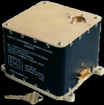
CEASE (Compact Environmental Anomaly Sensor Experiment), provided by AFRL, Hanscom Air Force Base, Bedford, MA (the instrument was built by Amptek Inc. of Bedford, MA). Objective: To demonstrate on-orbit autonomous monitoring of the S/C environment and to provide “alerts” when satellite charging, SEUs or other radiation events are likely.
The instrument also provides on request detailed data on particle fluxes incident on the spacecraft over the 72 hours prior to the request. This feature allows the S/C operator, once an anomaly has occurred, to have sufficient data to analyze and understand the cause of the anomaly. CEASE's output can be used to distinguish between natural effects and those caused by other (possibly hostile) actions. By on-board analysis of its measured space-environment data using decision making algorithms in its microprocessor, CEASE provides alerts/warnings in terms of a series of ascending order flags, indicating the likelihood and severity of the forthcoming anomalies.
The instrument has a size of 10 cm x 10 cm x 8.2 cm, a mass of 1 kg, and power consumption of <1.5 W. An RS-422 or 1553B interface is used. The instrument is also flown on the following missions: TSX-5 (Tri-Service Experiments Mission 5), launch June 7, 2000, and DSP [(Defense Support Program-21) satellite, launch Aug. 6, 2001].
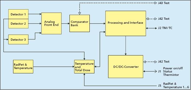
CREDO-II (Cosmic Radiation Environment and Dosimetry Experiment), provided by DERA, MoD, heritage of STRV-1b. Objective: To monitor those aspects of space radiation which cause single event effects in microelectronic components. The measurements comprise energetic proton fluxes from the inner radiation belt and solar flares, and the linear energy transfer spectra of heavy ions in cosmic rays and solar particle events. The instrument is as a compact, low power monitor housed on a single board. Two telescopes are employed, each comprising two pin diodes of area 3cm2 in coincidence, in order to define the arrival directions of the particles and their pathlength through the detector. In one telescope the charge depositions are amplified and pulse-height analyzed to give the linear energy transfer spectra, while in the other the counts above a low threshold are used to monitor the much higher proton fluxes. Counts are accumulated into programmable time bins to reflect the finer resolution required at perigee compared with apogee and to make optimum use of the limited data storage and telemetry.
DDM (Deep Dose Monitor), provided by DRE (Defense Research Establishment, Ottawa, Canada). Objective: To record the space radiation environment absorbed dose behind various thin shields and to estimate the dose due to low energy electrons. The DDM instrument is a small, low power, real-time dosimetry system consisting of four radiation sensitive dual MOSFETs (Metal Oxide Semiconductor Field Effect Transistors) which measure total dose during the mission. Each MOSFET has a unique shield covering the sensitive device to monitor the wide range of doses. The MOSFETs are capable of measuring high energy electrons and protons with dose levels between rad (radiation dose of energy) and Mrad.
GAGE (GPS At GEO Experiment), provided by MoD, DERA, DoD, JPL, and ESTEC. Objective: To characterize the GPS signal availability at selected altitudes up to GEO with particular emphasis on investigating the feasibility of GPS utilization on GEO satellites. The primary objective is to measure the GPS signal strengths at the L1 and L2 frequencies, to enable the definition of an operational GPS package for future spacecraft in high orbits up to GEO. GAGE consists of a patch antenna and GPS sampling device, known as `Bitgrabber', both provided by JPL. The device captures the GPS RF environment for short (up to 400 ms), predetermined periods of time and downlinks this information for subsequent processing. The ground segment of GAGE consists of observable extraction and orbit determination software to process the data obtained from the spacecraft and provide the mission results.
GFSE (Gas Flow Sensor Experiment), provided by DERA. Objective: To demonstrate in space a gas flow control and sensing principle (advanced xenon gas flow control and monitoring system) to test the range of UK ion thrusters developed by DERA. The flow sensor uses a thermal technique to measure the flow rate of gas. The gas flows through a small bore stainless steel tube around which is wound two identical coils of wire whose resistance is highly dependant on temperature. A small current is then passed through the wire which heats the coil. - The new system uses a novel thermal flow controller and an accurate, and highly sensitive, flow sensor. These units allow the system to be significantly smaller, cheaper, more flexible and, potentially, more reliable.
LCE (Linear Concentrator Experiment), provided by BMDO, NASA, USAF/PL. Objective: To measure the IV curves and to determine the pointing sensitivity of a new linear concentrator solar cell assembly.
MTB (Microwave Test Bed), provided by MMS, DERA, MoD. Objectives: To evaluate microwave SHF (Super High Frequency) technologies for future military space communication systems. MTB is a single channel transparent SHF (X-band) transponder, built using microwave and electronic components developed under the Matra Marconi Space (MMS) EXPERT satellite project.
PM (Proton Monitor), provided by Thomson & Nielsen Electronics Ltd, Canada, and sponsored by DRE, Ottawa. Objective: To flight-prove a monitor which measures the upset rate due to high energy protons and to compare the results with other on-board monitors and ground-based tests. Secondary objectives include:
• Correlation of the PM proton data with data from other radiation experiments and the AOE-2 experiment
• Correlation of the PM upset monitor data with single event effects/upsets data from other memory devices of STRV-1c
• To distinguish between solar protons, the trapped radiation environment and incident high energy cosmic rays.
The PM instrument consists of a dynamic RAM which is sensitive to proton-induced single event upsets. The experiment is designed to measure both the proton environment and the solar activity.
SCTE (Solar Cell Technology Experiment), provided by Mod, DERA, ESTEC, NRL, USAF/PL, EEV(English Electric Valve Co., UK), heritage of STRV-1b. Objective: To measure the IV curves of up to 47 new solar cell and coverglass technologies. In particular to:
• Demonstrate the use of different types of advanced solar cells in the space environment
• Determine the true absolute electrical performance of the cells
• Compare their relative resistance to the space radiation environment
• Compare actual flight degradations with those predicted from ground testing
• Provide flight data for advanced cells entering production to give satellite program managers confidence of their reliability and suitability for use on large projects.
There are two parts to the experiment: 1) The flight demonstration of advanced cells on the power generating panels of STRV-1c/d. Panel performance data is provided from the solar array current monitors in the spacecraft power system. 2) The in-flight measurement of the current-voltage characteristics of 38 individual solar cells. The temperature coefficients of some cells are measured throughout the mission.
SMX-1 (Sparc Microprocessor Experiment), provided by MoD, ESA, MMS, DERA and SEI (Space Electronics Inc.) San Diego, CA. The overall objective is to evaluate the ESA ERC32 chip set and advanced processing technologies and shielding experiments in the harsh space environment. SMX-1 consists of the ESA ERC32 chip set and components (some components are shielded). Three RADFETS to monitor the radiation dose on the SMX-1 board. Note: SMX-2, a similar ERC32 board, is flown on STRV-1d in a more shielded location.
SREM (Standard Radiation Environment Monitor), provided by ESA/ESTEC (developed by Contraves Space, Zürich, Switzerland); SREM is of REM heritage flown on STRV-1b and the MIR space station.. SREM is also being flown on PROBA. Objective: To map the radiation environment of GTO with high temporal and spatial resolution at post-solar minimum conditions. SREM detects and counts electrons, protons, and cosmic rays with a coarse spectral resolution. The measurement is based on examining the sizes of charge pulses generated by charged particles in silicon diodes polarized in reverse by a high voltage. Two of the three diodes are in-line and operate in `coincidence', where a charged particle passing though both is detected and identified. SREM also measures the total radiation dose encountered by SREM itself and at different remote locations onboard the satellite, by using RADFETS. 26) 27)
STRV-1d Sensor/Experiment Complement
CERTO/PLUS (Coherent EM Radio Tomography & Profiling the Limb with UV Sensors), provided by NRL. Objective: To map the ionospheric electron densities in the satellite's orbital plane and to study the evolution of 1-100 km sized low latitude irregularities using radio/optical tomography techniques. The CERTO/PLUS experiment consists of a three-frequency radio-beacon, antenna and an UV photometer. With these flight instruments and ground radio/telemetry receivers, integrated ionospheric densities are determined near the satellite orbit plane. This provides a two dimensional mapping of the ionosphere which assists in the understanding of the distortion and attenuation of radio frequency (RF) signals caused by naturally occurring ionospheric anomalies.
ECSE (Encrypted CCSDS Space Experiment), provided by MoD, DERA, MMS. Objective: To demonstrate a prototype secure CCSDS packet TM/TC system in an operational environment. a) Demonstration of ESA Packet Telecommand encrypt/decrypt, authentication, validation and anti-replay attack functionality; b) ESA Packet Telemetry encrypt/decrypt functionality, c) Extraction of security management functions onboard the spacecraft and simplified processing of these security management functions. The ECSE ground segment consists of telecommand and telemetry security layer software integrated into the primary STRV TM/TC processor workstation.
ECSE is composed of two segments: a space segment and a ground segment. The ECSE space segment consists of a number of switches, several electronic devices, and interfaces to the Sparc processor with the relevant software loaded.
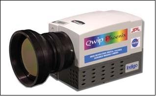
QWIP (Quantum Well Infrared Photodetector), an infrared camera system (a low-background QWIP FPA) provided by JPL (collaborative effort with Rockwell Science Center and at Raytheon SBRC) and sponsored by BMDO. The objective of the QWIP experiment is to demonstrate and assess QWIP FPA (Focal Point Assembly) uniformity, stability, and repeatability and responsivity in a space radiation environment.
The QWIP experiment consists of three components:
• The IDA (Integrated Dewar Assembly) including the cryocooler
• The blackbody assembly
• The electronics.
IDA and the blackbody assembly are installed on the bottom side of the S/C deck, covered with a thermal blanket. The IDA contains the QWIP FPA in an evacuated titanium dewar integrally mounted to the cryocooler. The dewar contains a motherboard ROIC (Readout Integrated Circuit). In the operational scenario, the experiment is turned on every few days to collect and transfer data to the S/C for downlink transmission. 28)
Another QWIP sub-experiment on STRV-1d is sponsored by DREO (Defence Research and Development) Ottawa, Canada. The objective is to explore the radiation effects on a new QWIP detector design (radiation detection performance within the 11-17 μm spectral region). The sub-experiment employs a passive radiator to cool the detector to 150 K. Measurements of the I-V curves of representative QWIP detector elements are gathered over the STRV-1d mission life under DHS (Data Handling System) control for post analysis by Canadian researchers.
Objective: To characterize the radiation detection performance of QWIP technology in the spectral range of 11-17 μm by imaging of the moon. The QWIP detector is mounted directly to the 55 K coldfinger of a 1 W tactical cooler (Texas Instruments) using an IDA. The test objectives include determining cooler/battery compatibility and measuring the power train efficiency, inrush current levels, and current ripple.
SAS (Satellite Attitude Sensor), provided by CREST (Canada). Objective: To demonstrate the capabilities of a new type of infrared Earth sensor over a range of altitudes from LEO to GEO in a harsh radiation environment on a slow-spinning satellite.
SCL (Spacecraft Command Language), provided by NASA, ICS (Interface Control Systems, US). Objectives: To monitor spacecraft systems.
SMX-2 (Sparc Microprocessor Experiment-2), provided by MMS, DERA, ESTEC. Objective: To demonstrate the ERC-32 Sparc chip-set in a harsh radiation environment and to demonstrate its ability to meet the platform OBC function and to support the experiments: ECSE, SCPS, SCL, and OBPE. The SMX-2 experiment consists of two Single electronic boards with the ESA Sparc ERC32 chip set incorporated into them. SMX-2 has 4 MByte of RAM and 2 MByte of EEPROM. SMX-2 is housed in the same box as ECSE.
BEPT (Bradford Engineering Pressure Transducer), provided by Bradford Engineering and sponsored by NIVR. The principal objective is to flight demonstrate BEPT. The instrument is used to measure the pressure in the operational cold gas attitude control system on STRV-1d.
InP/Si Solar Panel, provided by NRL.
GaAs/Ge Solar Panels, provided by ESTEC.
Lithium Ion Battery, provided by BNSC, DERA, AEAT (Atomic Energy Authority Technology, UK). The lithium-ion battery has half the mass of a conventional nickel-cadmium battery.
Demonstration Technologies
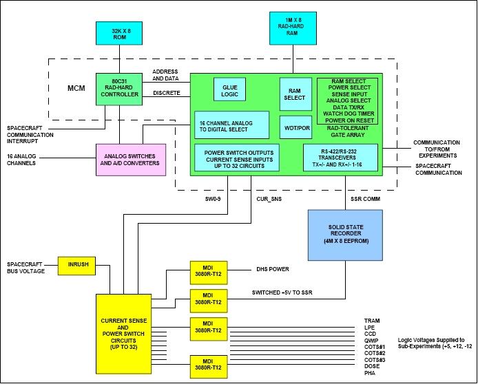
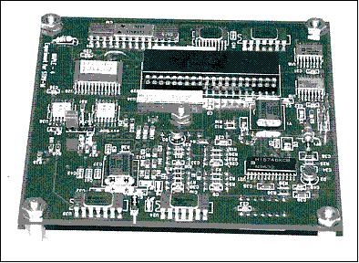
ETB (Electronics TestBed), provided by AFRL, Kirtland AFB, NM and sponsored by BMDO. ETB is a Data Handling System (DHS), providing a general purpose interface between multiple space flight experiments and the spacecraft. The DHS design simplifies some of the complexities by providing a simplified interface for operating the space experiment, recording the results, and communicating the results to the spacecraft. It also reduces the risk to the spacecraft mission by providing a degree of separation between the spacecraft and less-proven new technologies, and it provides a similar degree of separation between experiments. 29) 30)
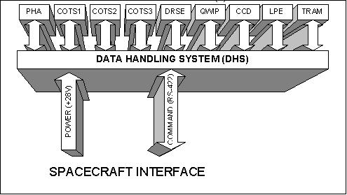
• PHA (Pulse Height Analyzer). ). The PHA is one of two ETB sub-experiments dedicated to improved dosimetry, in this case to establish measurements of the linear energy transfer (LET) value, which is an important indicator in the study of single event phenomena (SEP) in space-based micro-electronics, especially those involving commercial off-the-shelf (COTS) devices. As a side benefit, the PHA instrument is sensitive to phenomenology associated with solar flares. The indication of solar flares, which will be correlated with other sources during operation, can be exploited by the DHS to trigger a special operating sequence designed to examine more closely the SEP-sensitive elements of other particular sub-experiments.
• COTS #1 of NASA. This sub-experiment examines controversial elements of analog electronics in which the Elder's phenomena has been observed. Elder's effect refers to a dose-rate dependant degradation in bipolar transistors fabricated in certain IC processes.
• COTS #2 of NASA. This sub-experiment will examine synergistic radiation effects on a variety of newer state-of-the-art digital microcircuit and multi-chip module (MCM) technologies.
• COTS # 3 of NASA. The COTS #3 sub-experiment examines new photonics technologies, in particular optocoupler components that are under consideration for future NASA experiments. Motivation for COTS #3 came about due to problems experienced in certain newly installed optocouplers within HST (Hubble Space Telescope) during its passage through the SAA (South Atlantic Anomaly), which now prevent HST from operating there. These single event upsets did not occur in older optocouplers, which motivates further investigation of several different types of optocoupler devices, including those used in HST, by placing them into the COTS #3 experiment. In the COTS#3 experiment, a number of biased but non-illuminated optocouplers will be monitored for spurious pulse activity during operation through the radiation belts.
• DRSE (Dose Radiation Shielding Experiment) of NASA/BMDO. This sub-experiment provides a distribution of dosimeters in key spacecraft locations during the STRV-1d mission. The objectives of the DRSE experiment are to:
- 1) investigate a variety of shielding approaches, such as the RADCOAT technology and composite structure-based techniques; and
- 2) evaluate total ionizing dose throughout STRV-1d spacecraft.
A total of 24 individual monitoring nodes will be instrumented (with a total of 140 measurements), with each node containing a JPL-invented RADMON monolithic integrated circuit, augmented by an external Sandia National Laboratory-developed RADFET and thermometers. These devices provide a compact instrumentation approach for measuring total ionizing dose effects in conjunction with several different shielding filters. These data are essential for appropriate analysis of all ETB sub-experiments, as well as collateral STRV-1d experiments (not a part of ETB), such as the BMDO-sponsored QWIP camera experiment.
• LPE (Low Power Electronics) of DoD/AFRL. This venue of research is particularly enabling in space systems, where every required joule of energy comes with a price tag. The LPE sub-experiment demonstrates circuits 10 - 100 times more power efficient than current practice, and examines in particular: 1) reduction in feature size, and 2) digital/analog integrated co-design, and how these systems might perform in a synergistic environment. The heart of the sub-experiment is an advanced instrument controller (AIC), built in a 0.35 micron, 3.3 V CMOS technology for the central processing unit, two commercial memory devices (Hitachi 128 k x 8 SRAM and EEPROM), and a 70,000 device analog ASIC built in 2 micron CMOS (Orbit) process.
• CCD (Charge-Coupled Device) of AFRL. CCDs have significant potential applicability in a number of DoD missions, but these types of devices are notoriously susceptible to total ionizing dose in space missions. New types of CCDs, such as those under development at Lincoln laboratory, are promising in that they have a higher degree of radiation tolerance as do traditional versions. The CCD experiment will evaluate a Lincoln Laboratory-developed CCD (516 x 512 pixel arrangement) in a non-imaging configuration. A flood source will illuminate five exposed regions of the detector (each containing 5 x 5 pixels) of the otherwise opaquely masked CCD, which is cooled to a nominal -10ºC operating temperature through a thermoelectric. Two resistance-temperature detectors (RTDs) provide control loop sensing drive and instrumentation for follow-on calibration of data generated.
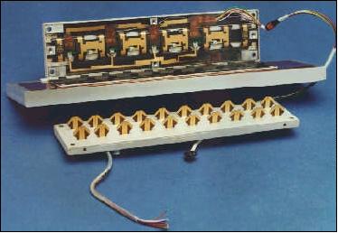
• TRAM (Transmit Receive Antenna Module) of AFRL. In support of space-based radar research, extremely light-weight components must be developed and validated. The ground radar concept of a transmit-receive (TR) module is further augmented to include antennas in the novel space-based concept demonstrated in the TRAM sub-experiment. A receive-only version of a TRAM system element (Figure 15) comprises a sub-experiment to examine the functional performance of a promising technology which unites key radar components with several types of aggressive packaging, including plastic and flex-based forms of the HDI (High Density Interconnect) process. The novel use of HDI as an antenna, along with the high-performance nature of the controlled impedance interconnect structures for microwave applications, led to modules which performed to within 0.7 dB of theoretical projections.
References
1) N. Wells, J. Eves, P. Mace, “Space Technology Research Vehicles STRV-1A and -1B, Final Report (DRA, ESA, BMDO) Vol. 1, August 1995
2) N. Wells, “The Space Technology Research Vehicles STRV-1A and -1B: Mission Update,” paper provided by the author
3) R. J. Blott, N. S. Wells, J. Eyes, “The STRV 1 microsatellite series: exploiting the geosynchronous transfer orbit,” Acta Astronautica, Vol. 41, No 4, August 1997, pp.481-492
4) http://space.jpl.nasa.gov/msl/QuickLooks/strv1QL.html
5) N. Wells, “Space Technology Research Vehicles (STRV-1a and -1b): Lessons Learned After four Years in GTO,” Proceedings of the 4th International Symposium on Small Satellites Systems and Services, Sept. 14-18, 1998, Antibes Juan les Pins, France
6) http://lasp.colorado.edu/strv/index.shtml
7) John Stubstad, Richard J. Blott, James Shoemaker, “Space Technology Research Vehicle (STRV)-1 program,” Proceedings of SPIE, 'Small Payloads in Space,' Brian J. Horais; Robert J. Twiggs, Editors, Vol. 4136, pp.1-7, Nov. 2000, DOI: 10.1117/12.406643
8) Richard J. Blott, Nigel S. Wells, Mathew Cosby, “The STRV family of spacecraft,” Air & Space Europe, Volume 2, Issue 1, January-February 2000, pp. 53-60, doi:10.1016/S1290-0958(00)80010-6
9) “Space Technology Research Vehicle STRV-1a and STRV-1b,” SSTL, URL: http://centaur.sstl.co.uk/SSHP/data/data_strv.html
10) I. L. Harris, A. R. Chambers, G. T. Roberts, “Results from the Space Technology Research Vehicle 1a Atomic Oxygen Experiment,” Journal of Spacecraft and Rockets, Vol. 35, No 5, Sept-Oct. 1998, pp. 647-652
11) STRV 1a: Experiments, http://lasp.colorado.edu/strv/exp1a_strv.html
12) Note: Differential charging of surface material occurs when these materials are electrically isolated, either from the S./C structure or from neighboring surfaces, or when the surfaces are insulators themselves. In these situations charge build-up cannot leak away, resulting in large potential differences between neighboring surfaces.
13) C. S. Dyer, C. J. Watson, C. L. Peerless, A. J. Sims, J. L. Barth, “Measurements of the Radiation Environment from CREDO-II on STRV and APEX,” IEEE Transactions on Nuclear Science, Vol. 43, No. 6, Dec. 1996
14) http://www.jpl.nasa.gov/adv_tech/coolers/Integ.htm
15) “STRV-1b: Experiments,” http://lasp.colorado.edu/strv/exp1b_strv.html
16) http://www.spenvis.oma.be/help/models/databases/strv1b.html
17) P. Nieminen, E. Daly, A. Mohammadzadeh, A. Hilgers, P. Bühler, W. Hajdas, “ESA’s Space Radiation and Plasma Monitoring Programmes,” WRMISS (Workshops on Radiation Monitoring for the International Space Station), Farnborough, UK, Nov. 1-5, 1999, URL: http://wrmiss.org/workshops/fourth/nieminen.pdf
18) Richard Blott, Nigel Wells, “ The Space Technology Research Vehicles: STRV-1A,B,C&D,” Proceedings of the AIAA/USU Conference on Small Satellites, Sept. 16-19, 1996, Logan, UT, http://klabs.org/DEI/References/avionics/small_sat_conference/1996/strv.pdf
19) A. Cant, H. Simpson, “STRV-1c & -d Satellite Architecture Design Document,” March 1998, provided by DERA
20) N. Wells, “STRV-1c & -d Mission Definition Specification,” Feb. 1998, provided by DERA
21) N. Wells, R. Blott, “STRV-1c&d Program Update,” Proceedings of the 11th AIAA/USU Conference on Small Satellites, Sept. 15-18, 1997, Logan, UT
22) N. S. Wells, “Development of the STRV 1c and 1d mission based on the experiences of STRV-1a and -1b,” Proceedings of the Institution of Mechanical Engineers, Part G: Journal of Aerospace Engineering, Vol. 213, No 4, 1999, pp. 233-243, ISSN 0954-4100
23) N. Wells, “Countdown to launch of the first microsatellites qualified for flight on Ariane-5 ASAP,” Proceedings of the 14th Annual AIAA/USU Conference on Small Satellites, Logan, UT, Aug. 21-24, 2000, SSC00-I-7
24) K. Avery, “Lessons Learned: STRV 1c/d Mission,” 2004 MAPLD International Conference, Washington D.C., Sept. 8-10, 2004, http://klabs.org/mapld04/tutorials/mishaps/strv1c_d.htm
25) http://klabs.org/mapld04/tutorials/mishaps/presentations/10_strv-1cd_avery.ppt
26) SREM - Standard Radiation Environment Monitor,” Contraves, URL: http://www.oerlikon.com/ecomaXL/get_blob.php?name=SREM_Brochure&download=1
27) “SREM onboard STRV1-c,” ESA, URL: http://space-env.esa.int/R_and_D/SREM/index.html
28) J. T. Kenny, H. R. Pollock, “STRV-1d QWIP technology validation in space flight,” Infrared Physics & Technology, Vol. 42, Issue 3-5, 2001, pp. 385-390
29) Jim Lyke, Paul Brezna, Keith Avery, “BMDO/AFRL Partnership: Advances In Data Handling Systems For Space Experiment Control,” Annual MAPLD (Military and Aerospace Applications of Programmable Devices and Technologies) International Conference, Sept. 26-28, 2000, Laurel MD, USA
30) J. Lyke, P. Brezna, K. Avery, “BMDO/AFRL Partnership: Advances In Data Handling Systems For Space Experiment Control,” AIAA-98-09-06, URL: https://web.archive.org/web/20100714155000/http://klabs.org:80/richcontent/MAPLDCon00/Abstracts/lyke3_a.pdf
The information compiled and edited in this article was provided by Herbert J. Kramer from his documentation of: ”Observation of the Earth and Its Environment: Survey of Missions and Sensors” (Springer Verlag) as well as many other sources after the publication of the 4th edition in 2002. - Comments and corrections to this article are always welcome for further updates (eoportal@symbios.space).