STEX (Space Technology Experiment)
Non-EO
Quick facts
Overview
| Mission type | Non-EO |
| Launch date | 03 Oct 1998 |
STEX (Space Technology Experiment) / ATEx
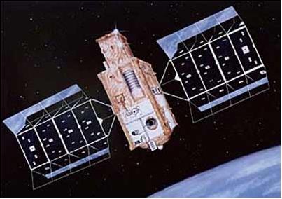
STEX was a low-cost and low-mass technology demonstration mission sponsored by the US NRO (National Reconnaissance Office), an intelligence-gathering agency of DoD, and operated by AS&T (Advanced Systems and Technology) of NRO. In this program which started in 1995, NRO took advantage of partnerships with industry and other (DoD) agencies - such as: NRL (Naval Research Laboratory), AFRL (Air Force Research Laboratory), NASA/GRC, Primex Aerospace, MDA (Missile Defense Agency, formerly BMDO), The Aerospace Corporation, and Russia's Central Scientific Research Institute of Machine Building (TsNIIMASH) - to optimize the use of their unique talents and resources. The main experiment equipment of STEX (Hall effect thrusters, experimental solar arrays, and ATEx) was provided by NRL, Washington, DC.
The overall objective was to demonstrate high-performance spacecraft technologies (29 in all) in space. The experiments conducted provided potential improvements in spacecraft technology for both military and civil satellites. - Note: The STEX satellite happens to be the first mission the NRO had announced prior to launch, a positive sign of more openness after the end of the Cold War.
Spacecraft
The STEX spacecraft was built by Lockheed Martin Astronautics Corp. (LMA) of Denver, CO as prime contractor. The spacecraft was comprised of a body shell using low-mass composite structures and two tracking solar panels. The STEX bus included the feature MFS (Multifunctional Structure), an innovative and enabling design approach (eliminating “black boxes”, lots of cabling, harness, bulky connectors, etc.) by integrating spacecraft electronics, structural, and thermal control functions into a single structure. In particular, the MFS concept involves embedding passive-electronic components within the actual volume of composite materials, new approaches to attaching active-electronic components directly to mechanical surfaces, using surface areas for mounting sensors and transducers. This new packaging technology development reduces spacecraft mass and volume considerably. The MFS initiative was sponsored by AFRL and BMDO (Ballistic Missile Defense Office).
The first MFS demonstration was flown on DS1 (Deep Space 1, launch Oct. 24, 1998) of NASA, the second on EO-1 (Earth Observing, launch Nov. 21, 2000) of NASA, and the 3rd test was on the STRV-1d (Space Technology Research Vehicle-1d, launch Nov. 16, 2000) mission of DERA, UK. 1) 2)
The STEX spacecraft was three-axis stabilized. A lightweight precision star tracker was used to determine satellite pointing. The EPS (Electrical Power Subsystems) employed experimental high-efficiency solar array concentrators as well as high-density NiH2 (Nickel Hydrogen) batteries designed to last longer and provide more energy with less weight (than conventional NiCd batteries). A blowdown liquid propulsion system was provided for orbit raising and maintenance functions. STEX featured also a high-performance onboard computer with the largest solid-state recorder of 51 Gbit capacity (memory) built so far for a spaceborne application. The recorder was developed by SEAKR Engineering Inc. of Englewood, CO with a first introduction of the 64 Mbit DRAM technology in a space based environment. The STEX spacecraft had a launch mass of 693 kg and a design life of two years.
The ADCS (Attitude Determination and Control Subsystem) of STEX employed, among other components (star tracker, sun sensors, and actuators), also a software package of The Aerospace Corporation (El Segundo, CA) for demonstration purposes, called PseudoGyro, emulating virtual gyros through software processes. PseudoGyro works in conjunction with orbital-attitude-estimation filtering techniques and takes advantage of all available sensors, including the vehicle itself, in determining attitude. It uses the principle of conservation of momentum to accurately determine the angular velocity of a spacecraft. It can be applied to virtually all types of space vehicles that are controlled by any type of momentum storage device. The technology can be integrated before or after a satellite is in orbit. In general, gyroscope-mimicking software might not replace replace the real thing, but it can reduce the workload on gyros, thereby extending their lives. PseudoGyro addresses also the need to reduce the risks and costs associated with new technology gyros. The PseudoGyro function was successfully tested in the STEX mission for the first time. 3)
Launch
The STEX spacecraft was launched on October 3, 1998 on a Taurus vehicle of OSC from VAFB, CA (third flight of OSC's ground-launched Taurus rocket).
Orbit: near-circular orbit, altitude of about 750 km of final orbit, inclination = 85º.
Mission Status
STEX successfully tested 29 advanced technologies and/or subsystems for spacecraft before being turned off in early June 2000. Some of the advanced technology subsystems successfully tested on STEX include: 4) 5)
• Shockless separation mechanisms that will pave the way for future satellites to be designed for extremely low shock levels, saving cost and weight.
• Lightweight, high accuracy autonomous star trackers provided valuable data on their operation in low earth orbit and how to mitigate radiation effects.
• A 20 MHz RAD 6000 processor, the fastest in space, performed flawlessly and required no reboots.
• The largest solid state recorder in space (51 Gbit capacity) at the time was fully checked out and also performed perfectly.
• An electric propulsion engine from the Naval Research Laboratory (EPDM) was the first use of a Hall effect thruster on a US spacecraft.
• The advanced lightweight batteries had a 35% greater capacity than conventional batteries.
• High efficiency solar array concentrators focused 70% more light on the arrays than standard systems.
• Advanced dual junction solar cells provided 23% more power than standard solar cells.
Experiment Complement (ATEx, SoftRide, EPDM)
Only a subset of the experiment complement and technologies are described due to unavailable documentation.
ATEx (Advanced Tether Experiment)
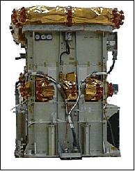
ATEx is of TiPS (Tether Physics and Survivability) heritage, designed and built by NCST (Naval Center for Space Technology). ATEx was comprised of two end masses connected by a polyethylene tether of 6 km in length. ATEx had three mission objectives: a) to demonstrate tether system stability and control, b) demonstrate end-body attitude determination and control, and c) fly a tether designed for survivability.
ATEx was intended to test a new tether deployment scheme that was implemented as a tape over 6 km long and 3 cm wide, with reinforcements consisting of fiber strands running down its length. ATEx experiments in active control were to study deployment dynamics via a constant-speed motor and utilization of both in-plane and cross-plane thrusters to excite and arrest librations. Additionally, ATEx was to investigate the survivability of long-life tether materials. 6) 7)
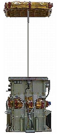
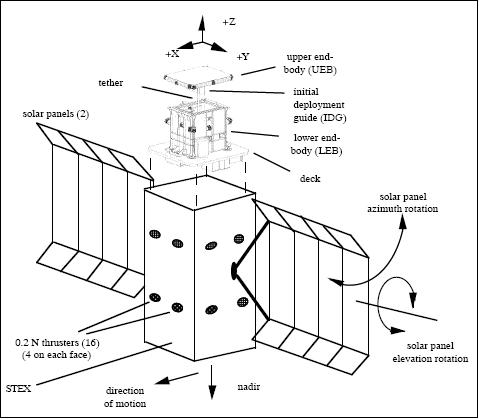
Figure 3 illustrates the ATEx/STEX configuration and the spacecraft coordinate X, Y , and Z axes relative to an orbital frame in its nadir pointing attitude. During the initial deployment phase, the spacecraft was operated as a three-axis-stabilized momentum-bias vehicle. A momentum wheel, with its spin axis parallel to Y , had its speed modulated to control the pitch axis, and electromagnetic torque rods were used to control the roll and yaw axes. The attitude control system operated at a rate of 0.1 Hz, with an effective bandwidth of 0.01 Hz. The solar arrays were each gimbaled in elevation and azimuth with respect to the central body. The arrays were held fixed early in the deployment, though not in the null position shown in Figure 3. 8)
ATEx was released from the STEX spacecraft on 16 January 1999 and ended 18 minutes later after deploying only 22 m of tether. The ATEx tether pair was inadvertently jettisoned from the STEX spacecraft due to an out-of-limits condition sent by the experiment's tether angle sensor. The jettison mechanism was triggered by the automatic protection system, designed to save STEX spacecraft if the tether strayed from its expected departure angle. As a result of the deployment failure, none of the desired ATEx goals were achieved. 9)
Note: The ATEx lower end mass was meant to remain attached to the STEX parent spacecraft, but with only 22 m of tether deployed, it appeared the tether was so far off the vertical that automatic safety systems jettisoned the base to protect the remainder of the STEX satellite. Thus, the upper and lower ATEx end masses were in orbit as one object connected by a 22 m tether; they were designated as USA 141 (1998-055C). The main STEX satellite was in orbit as a separate object, designated as 1998-055A.
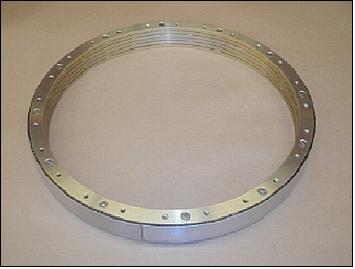
SoftRide Vibration Isolation System
SoftRide is a ”whole-spacecraft vibration isolation system” developed for the Taurus launch vehicle of OSC. The SoftRide package, a single-axis axial isolation system, was designed and developed by CSA Engineering Inc. of Palo Alto, CA, and AFRL. The first flight of the SoftRide package took place on the launch of the GFO (Geosat Follow-On) spacecraft (launch Feb. 1998). The objective of SoftRide is to reduce axial dynamic responses on the spacecraft due to resonant burn excitations from the motors of the solid-fueled booster. 10) 11) 12)
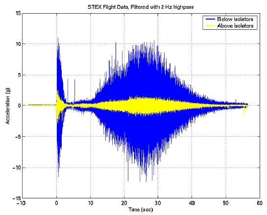
A review of flight data from the GFO and STEX flights has shown significant reduction, not only in transient vibration, but also in random vibration and shock. Structural-borne vibrations at the worst loading conditions were reduced at least by a factor of five. Overall, the system reduced vibration levels for the other load cases by more than a factor of three. Figure 7 shows the axial acceleration data measured below and above the SoftRide isolators.
The SoftRide package (a first generation system) has been installed on the following space missions:
- GFO (GeoSat Follow-On) spacecraft (launch Feb. 10, 1998)
- STEX (Space Technology Experiment) spacecraft (launch Oct. 3, 1998)
- JAWSAT spacecraft (launch Jan. 26, 2000)
- MTI (Multispectral Thermal Imager) spacecraft of LANL (launch March 12, 2000)
- MightySat spacecraft (launch July 19, 2000)
- QuikTOMS (Quik Total Ozone Mapping Spectrometer) spacecraft and OrbView-4 spacecraft (launch Sept. 21, 2001)
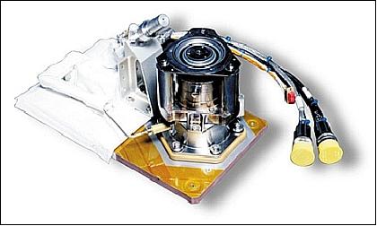
EPDM (Electric Propulsion Demonstration Module)
The EPDM instrument represents the first operational Hall effect propulsion system on a western spacecraft (although the Hall effect technique was initially developed in the 1960s, this technology was not really implemented during the last 25 years until its first space flight demonstration on STEX). NASA was heavily involved in transitioning the Russian developed Hall thruster technology for use on US spacecraft. The EPDM was developed jointly by NASA/GRC, NRL, Primex Aerospace, MBA (formerly BMDO), and by the Central Scientific Research Institute of Machine Building (TsNIIMASH), Korelev, Russia. The overall objective of EPDM device was to demonstrate an orbit-raising and station-keeping capability without chemical propulsion. 13) 14) 15)
EPDM is a 660 W xenon Hall thruster system, an electrostatic propulsion device (Isp= 1500 s, or about 15,000 m/s), consisting of the following major subsystems:
• PPU (Power Processing Unit), featuring 5 separate power supplies (90% efficient). PPU was built by Primex Aerospace Corp. of St. Petersburg, FL. PPU consists of five separate but interrelated power supplies. The anode supply provides a regulated 300 V to the TAL-D55 thruster. The PPU has an electrical conversion efficiency of about 90% with an input voltage of 30 V. The 65 W of waste heat is dissipated through the baseplate of the unit, and the spacecraft rejects it to space. The mass of PPU is 10.3 kg.
• EA (Engine Assembly), consisting of a TAL-D55 (Thruster with Anode Layer) Hall thruster which has a nominal discharge of 1.35 kW at 300 V. In flight, EA is used at 600 W discharge (300V @ 2.2 A), limited by the spacecraft's power. EA has a mass of 4.35 kg. The thruster is mounted on top of a titanium thermal isolator to minimize the conductive heat path back to the spacecraft. The engine and isolator are mounted on a small aluminum honeycomb panel along with the orifice block and the cathode assembly. The orifice block splits the flow of the low-pressure xenon between the TAL-D55 thruster and the cathode. Precision orifices and tight temperature control on the orifice block itself maintain the accurate single point mass flow setting. During system operation, a set of stored spacecraft commands is executed to initialize and thermally condition the system, and to fire the thruster.
• XFS (Xenon Flow System), featuring a high pressure gas storage (5,654 kPa), xenon fuel of 2.7 kg, total mass of 6.8 kg. XFS is a high-pressure storage system with regulated pressure and mass flow. The xenon is stored in a 20 cm spherical tank at a pressure of 64 kg/cm2. Two solenoid valves upstream of the pressure regulator control the flow. A high-pressure transducer accurately determines the amount of xenon remaining. Thermostatically controlled heaters provide thermal conditioning.
• AIU (Auxiliary Interface Unit), a customized spacecraft interface. AIU conditions discrete commands and telemetry (analog and discrete) and provides thermal conditioning of the XFS, the engine assembly, and XFS valve drivers. The AIU changes pulsed discrete commands into steady-state commands required by the PPU. An electronic thermostat accurately controls the temperature of the orifice heaters in the xenon flow system. The mass of AIU is 1.9 kg, it consumes an average of 6 W.
The Hall thruster as used in EPDM is a non-toxic, electric propulsion technology, which can be used for Earth orbital and in-space applications including orbit raising, on-orbit maneuvers, delta V and de-orbit functions. The telemetry data and trajectory measurements of the STEX mission showed that the engine operating parameters were in compliance with the characteristics obtained in ground laboratories.
Background
The successful results of the 5-year comprehensive TAL evaluation program in the US laboratories conducted by TsNIIMASH with NASA support had attracted the interest of industry. The positive flight experience of the EPDM on STEX was a major boost for all parties involved. This resulted also in further trials of TAL-based devices of 0.5 to 25 kW power rating.
Already in 1997, a joint program development of electric Hall thrusters by TsNIIMASH and the Boeing Company was initiated. The program goal was to create a new thruster for the demand of envisioned space transportation services, such as for the “Teledesic” project (at the time a proposed large communication satellite constellation in LEO). In the short period of a year, a Russian and American version of the TAL-D110 thruster were developed and tested as a result of a team effort by TsNIIMASH and Rocketdyne Propulsion and Power (then a unit of the Boeing Company). This engine featured high efficiency in all operating modes supporting such functions as satellite orbit raising, as well as repositioning and drag compensating for a spacecraft. 16)
References
1) D. M. Barnett, S. Rawal, K. Rummel, “Multifunctional Structures for Advanced Spacecraft,” Journal of Spacecraft and Rockets, Vol. 38, No 2, March-April, 2001, pp. 226-230
2) M. F. Zedd, “Experiments In Tether Dynamics Planned For ATEx's Flight,” Proceedings of the Tether Technology Interchange Meeting, NASA/MSFC, Huntsville, AL, Sept. 9-10, 199
3) L. K. Herman, C. M. Heatwole, G. M. Manke, ”Attitude Determination for the STEX Spacecraft Using Virtual Gyros,” Guidance and Control 2001,: Proceedings of the Annual AAS Rocky Mountain Conference, Breckenridge, CO, Jan. 31-Feb. 4, 2001), pp. 113-132. AAS paper 01-008
4) “NRO Space Technology Experiment Completes Mission,” URL: http://www.spaceref.com/news/viewpr.html?pid=3147
5) “Space Technology Experiment Satellite Completes Mission,” http://www.nro.gov/PressReleases/prs_rel31.html
6) http://nssdc.gsfc.nasa.gov/nmc/spacecraftDisplay.do?id=1998-055C
7) http://code8100.nrl.navy.mil/programs/atex.htm
8) Stephen S. Gates, Stephen M. Koss, Michael F. Zedd, “Advanced Tether Experiment Deployment Failure,” Journal of Spacecraft and Rockets, Vol. 38, No. 1, January–February 2001, pp.60-68, URL: http://dyna15.narod.ru/kts/lit/gates_koss_zedd2001.pdf
9) Stephen S. Gates, Stephen M. Koss, Michael F. Zedd, “Advanced Tether Experiment Deployment Failure,” AAS/AIAA Astrodynamics 1999, Vol. 103, Advances in the Astronautical Sciences, AAS 99-413, Aug. 16-19, 1999, Girdwood, AK, USA
10) Paul Wilke, Conor Johnson, Patrick Grosserode, Dino Sciulli, “Whole-Spacecraft Vibration Isolation for Broadband Attenuation,” IEEE Aerospace Conference, Big Sky, Montana, USA, March 19-25, 2000, URL: http://www.dtic.mil/cgi-bin/GetTRDoc?Location=U2&doc=GetTRDoc.pdf&AD=ADA451903
11) P. S. Wilke, C. D. Johnson, “Reduction of Launch Shock Loads on Satellites Using a Shock Isolation System,” June 26, 2002, URL: http://www.aero.org/conferences/sclv/pdfs/Johnson_Wilke_ShockIso.pdf
12) P. S. Wilke, C. D. Johnson, P. J. Grosserode, D. Sciulli, “Whole-spacecraft vibration isolation on small launch vehicles,” Proceedings of SPIE Vol. 3989, pp. 440-451, Smart Structures and Materials 2000: Damping and Isolation, T. Tupper Hyde; (Ed.)
13) John M. Sankovic, “NASA Technology Investments in Electric Propulsion: New Directions in the New Millennium,” Third International Conference on Spacecraft Propulsion, Cannes, France, Oct. 10-13, 2000, URL: http://gltrs.grc.nasa.gov/reports/2002/TM-2002-210609.pdf
14) P. R. Lynn, et al., “Electric Propulsion Demonstration Module (EPDM) Flight Hall Thruster System,” Proceedings of the 25th IEPC (International Electric Propulsion Conference), Cleveland, OH, August 24-28, 1997, IEPC 97-100., URL: http://sgc.engin.umich.edu/erps/IEPC_1997/97files/7100.PDF
15) J. M. Sankovic, L. Caveny, P. Lynn, “The BMDO Russian Hall Electric Thruster Technology (RHETT) Program From Laboratory to Orbit,” AIAA 97-2917, July 1997
16) D. F. Fulton, S. O. Tverdokhlebov, “Boeing/TsNIIMASH Joint Electric Propulsion Program,” 35th AIAA/ASME/SAE/ASEE Joint Propulsion Conference and Exhibit, Los Angeles, CA, June 20-24, 1999, AIAA-99-2282
The information compiled and edited in this article was provided by Herbert J. Kramer from his documentation of: ”Observation of the Earth and Its Environment: Survey of Missions and Sensors” (Springer Verlag) as well as many other sources after the publication of the 4th edition in 2002. - Comments and corrections to this article are always welcome for further updates (eoportal@symbios.space).