SpriteSat (Rising)
EO
Operational (nominal)
Tohoku University
Quick facts
Overview
| Mission type | EO |
| Agency | Tohoku University |
| Mission status | Operational (nominal) |
| Launch date | 23 Jan 2009 |
| CEOS EO Handbook | See SpriteSat (Rising) summary |
SpriteSat (Rising)
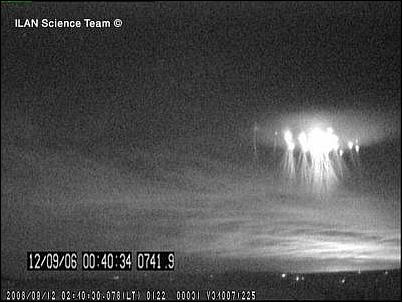
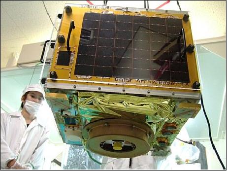
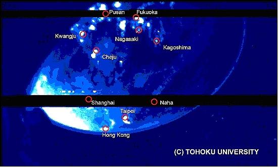
SpriteSat is an Earth science microsatellite designed and developed by the faculty and students of Tohoku University of Sendai (Miyagi Prefecture), Japan. The objective is to monitor luminous emissions in the upper atmosphere, called sprites. 1) 2) 3)
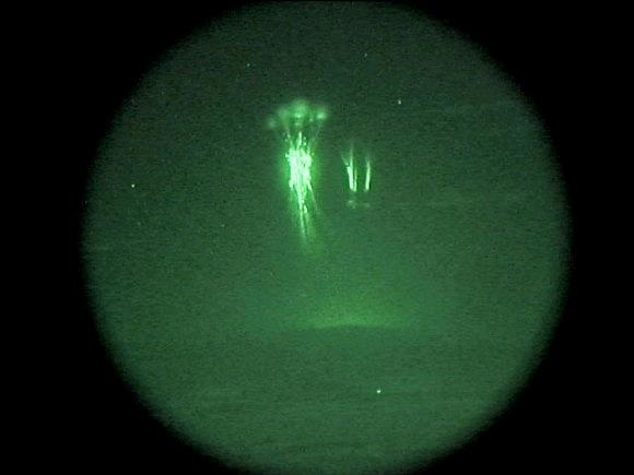
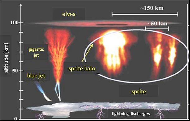
TLEs (Transient Luminous Emissions - or, Transient Luminous Events) are rather frequent natural phenomena induced by lightning discharges which occur about four-million times/day on a global scale. TLEs occur in the Earth's upper atmosphere, they are normally accompanied by thunderstorms in the lower atmosphere. There are various types of TLEs which were given such phantasy names as blue jets, sprites, elves, giant jets, etc. 4)
Upward lightning discharges into clear air have been reported by pilots worldwide since the start of the early 20th century. However, the first visual evidence of a TLE phenomenon was documented by scientists from the University of Minnesota on Sept. 22, 1989. An image of an unusual luminous electrical discharge over a thunderstorm 250 km from the observing site had been obtained with a low-light-level television camera. - Several years after their discovery, the optical signatures of these events were named 'sprites' by researchers at the University of Alaska. The terms “elves”, “red sprites”, “blue jets” and “TGFs (Terrestrial Gamma-ray Flashes)” gained popularity after a video clip was circulated following an aircraft research campaign to study sprites in 1994. 5) 6) 7) 8)
Although extensive studies on sprites have been made since their first documentation in 1989, the characteristics and even the fundamental mechanisms of sprites cannot be fully explained so far. The quasi electrostatic (QE) model proposed in the 1990s is considered as a standard model for sprite generation. However, the simple QE model is not enough to explain the time and spatial variations of sprites, such as the long time delay and horizontal displacement from parent cloud-to-ground discharge (CG), and the horizontal distribution and number of columns in a sprite event. - Concurrent measurements of lightning discharges and TGFs from space are important to understand the relationship between these phenomena. Nadir observations of sprites and TGF-related lightning are, therefore, significant for understanding of the generation mechanisms both of sprites and TGFs.
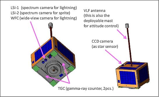
SpriteSat is equipped with three nadir-looking cameras, a VLF receiver and a gamma-ray detector. Specific mission objectives are:
• To observe sprites (TLEs) in the middle atmosphere, typically in the altitude range of 40-90 km, from the upper stratosphere to the mesosphere
• To observe the brief bursts of gamma rays in Earth's atmosphere which are referred to as TGFs (Terrestrial Gamma-ray Flashes).
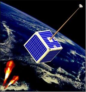
Spacecraft
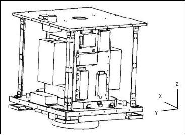
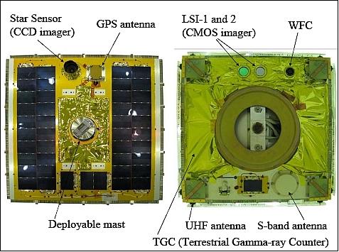
The spacecraft structure is cubical with a side length of 49 cm. AOCS (Attitude and Orbit Control Subsystem): Spacecraft stabilization is provided by a deployable gravity gradient boom which was newly developed for SpriteSat. The nominal attitude of the spacecraft is oriented in such a way that the bottom panel of the satellite (-Z panel) is always directed toward Earth. During the detumbling phase, two single-axis magnetic torquers are used to minimize the spin motion of the S/C prior to the boom deployment and to damp the libration motion after the deployment. 10) 11)
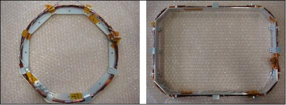
TAMU (Tohoku-ÅAC MEMS Unit) is an advanced magnetometer subsystem developed at Ångström Aerospace Corporation (ÅAC) of Uppsala, Sweden. In November 2008, the company changed name to ÅAC Microtec. The objective is to provide the AOCS with magnetometer data of the Earth's magnetic field for correlation with the sprite observations. The experimental TAMU is composed of four types of devices manufactured using leading-edge technologies: a 3-axis geomagnetic sensor, an MPU chip fabricated by 3D-system-in-package technology, a 4 Mbit MRAM (Magnetic Random Access Memory) chip and an IMU (Inertial Measurement Unit) chip. Especially the geomagnetic sensor and IMU will significantly contribute to making the scientific data more valuable. 12)
The emerging MRAM technology combines magnetic materials and silicon integrated circuitry to form a fast, reliable, non-volatile RAM (NVRAM). TAMU combines non-volatile memory with extended temperature operation, unlimited endurance, and long-term data retention, even when the power fails.
TAMU includes three-axis magnetometers, three-axis gyro sensors, and three-axis accelerometers.
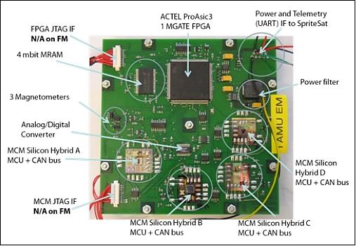
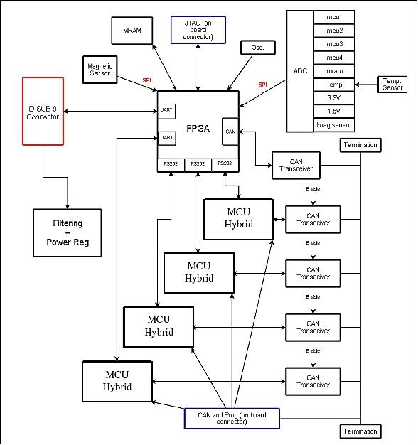
TAMU uses a distributed architecture to increase the probability of detecting errors and acquire statistically significant data. Figure 6 shows the block diagram of TAMU excluding the IMU add-on, where the CAN bus structure and the serial UART (RS232) architecture are clearly seen. A large number of parameters are collected per second and transmitted via telemetry to the ground for analysis. Based on the current measurements and CRCs (Cyclic Redundancy Checks), it should be possible to draw conclusions on the number of SEU (Single Event Upset) and SEL (Single Event Latch-up) events that occur throughout the mission.
The primary goal of ÅAC is to evaluate the performance of its thin-film metallization and flip-chip bonding technology.
Spacecraft size | W 490 x D 490 x H 494 mm |
Spacecraft mass | 45.3 kg |
Attitude control | Type: gravity gradient stabilization |
Attitude and orbit sensors | 3-axis sun sensors (6 solar cells) |
Power subsystem | Solar cells: P-type single crystalline silicon, 42 series/panel x 5 panels |
RF communications | Uplink: UHF, 1200 bit/s at Sendai station, Japan |
Launch
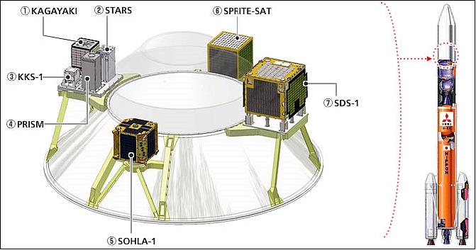
SpriteSat was launched on January 23, 2009 as a multiple secondary payload. The primary payload is the GOSAT spacecraft. The launch site is the Tanegashima Space Center, Kagoshima, Japan.
The seven secondary payloads on this flight are: 13) 14)
- SDS-1 (Small Demonstration Satellite-1) of JAXA (~100 kg)
- SOHLA-1 (Space Oriented Higashiosaka Leading Association-1), Japan (50kg)
- SpriteSat (Tohoku University), Japan (microsatellite of ~50 kg)
- PRISM (Picosatellite for Remote-sensing and Innovative Space Missions) of ISSL of the University of Tokyo, 5 kg
- Kagakaki (SORUNSat-1), Japan, 20 kg
- KKS-1 (Kouku Kosen Satellite-1) of Tokyo Metropolitan College of Industrial Engineering), nanosatellite of 3 kg
- STARS-1 (Space Tethered autonomous Robotic Satellite-1) of Kagawa University, Japan, ~ 10 kg.
Orbit: Sun-synchronous circular orbit, altitude = 666 km, inclination = 98º, LTAN (Local Time at Ascending Node) at 13:00 ± 0.15 hours.
Mission Status
• The SpriteSat spacecraft main controller experienced a problem and a subsequent operational failure after mast deployment. Hence, scientific observations could not start at all -although the project is still in contact with the spacecraft as of spring 2011. 15) 16)
SpriteSat was successful in many aspects, but not fully successful in onboard electronics. The project learned a lot of precious lessons from operating this spacecraft.
The project team invested a lot of time and effort to identify the problems happening in SpriteSat and the consequences of possible improvements for future missions. Careful experiments using the engineering models of the flight hardware and extensive analyses were conducted. A number of review meetings were also conducted with external experts. After an extensive process of failure analysis, the project came to the following conclusions/understanding.
1) There was a mistake in the design of the battery charging system. Due to this mistake, the temperature of the battery can go up to a critical level after reaching a full-of-charge status. This phenomenon was observed it in the early days of operation, the follow-up operations were conducted with an increased power consumption with some science instruments turned on.
2) Temporally a low voltage condition occurred in the power bus system - after the deployment of the gravity mast. This was because the balance of electrical charging and discharging was lost due to an increased shadow on the solar-cells from the extended mast.
3) Due to the temporary low-voltage condition, the main controller logic (which was constructed by FPGAs) went into a malfunctioning state. As a consequence, the functions of the command analysis from the uplink radio and the signal modulation to the downlink radio were disabled.
4) The power subsystem was reset by a safety switch to turn off the excessive power load. Then the power generation and consumption are well balanced. Now the power system is very stable, however we lost the means to reset the subsystem. The situation may be changed by another event of low voltage of the system.
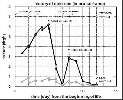
5) The reason of the increment of the attitude tumbling rate was confirmed due to an eddy current in each panel with solar cells. This is a problem of serial arrangement of multiple solar cells on a panel (Ref 15).
• In the evening of Feb. 4, 2009, just about half a day after the successful boom deployment, SpriteSat experienced problems in the OBC. The symptoms: the spacecraft was transmitting only a carrier wave (without any signal data modulation) in the S-band downlink and it did not respond to any uplink commands. The S-band carrier downlink continued operating, even through April 2011, during the day-side and the night-side of the orbit. This means that the onboard power generation and buttery system is still functional and stable. Also observed from the amplitude of the S-band carrier wave, it is inferred that the spin-rate of the spacecraft is constantly increasing in spite of the extended gravity mast. - This trend was also observed from 1st to 5th and 7th to 8th day as shown in Figure 12 (Ref. 15).
• A test image of the WFC, a high-sensitivity CCD imager with a fish-eye lens, was taken almost 12 hours before the boom deployment (Figure 13).
• Initial attitude operation was successfully conducted. The gravity boom and VLF antenna were deployed on Feb. 4, 2009.
In the initial operation period, a MEMS technology demonstration package named TAMU (Tohoku-AAC MEMS Unit), was successfully tested. TAMU includes multiple commercial-off-the-shelf components, including 8051 microcontrollers, 4 Mbit Magnetic RAM, and CAN-bus interface, and all these components worked normally in the orbital environment. Attitude measurement devices also worked well to record the de-tumbling and attitude damping sequence.
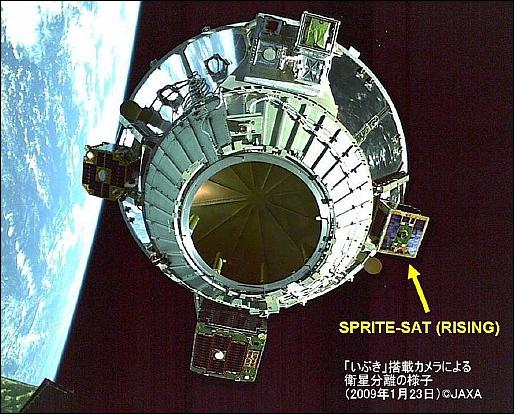
• SpriteSat has been successfully operated from the ground station in Tohoku University, after the successful launch and orbital insertion. The international ID and catalog number of SpriteSat is: 2009-002C 33494. In Japanese tradition, SpriteSat was given the nickname Rising after the initial signal acquisition from the spacecraft in orbit.
Sensor Complement
The sensor complement consists of five scientific instruments: two CMOS cameras with different color interference filters, a CCD camera with fish-eye lens, a gamma-ray detector, and a VLF radio wave receiver. All observations are taking place when the satellite is in the ±20º latitude range of the orbital eclipse.
LSI-1 (Lightning Spectrum Imager-1)
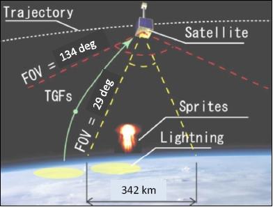
The objective is to detect lighting flashes. The camera features a CMOS detector with a format of 512 x 512 pixels. Observations are being made in the spectral band of 740-782 nm. LSI-1 and LSI-2 have a square FOV of 29º corresponding to a ground surface side length of 342 km (Figure 14).
LSI-2 (Lightning Spectrum Imager-2)
The objective is to detect sprites. The camera features a CMOS detector with a format of 512 x 512 pixels.. Observations are made in the spectral band at 762 nm.
WFC (Wide Field-of-view Camera)
The camera is being used to determine the location of lightning flash which is relating to the TGF event. This high sensitivity panchromatic CCD camera with a fish-eye lens covers 140º.
TGC (Terrestrial Gamma-ray Counter)
TGC is provided by JAXA/ISAS and the University of Tokyo with a FOV (Field of View) = 134º x 180º detects gamma-ray flashes caused by lightning discharges with an time resolution of 0.25 ms.
Star Tracker (Camera)
The objective is to provide additional attitude information with an accuracy of ~0.1º at the best conditions.
VLF receiver:
The VLF receiver is provided by Stanford University (Stanford, CA). The VLF receiver uses the spacecraft boom as its antenna. The objective of the VLF receiver is to measure the radio emissions from channels of lightning discharges not only of cloud-to-ground but also of intra-cloud discharges.
The triggers for the detection of lightning events are the luminous regions in the image data (of the LSI), the signal strength of the VLF receiver, or the gamma-ray detection by TGC.
The frequency of a sprite observation is estimated to occur about 0.5 to 1 times per day. For each sprite event 4 successive images for each LSI channel will be obtained, with each image data size of about 260 kB. For TGFs, the observation frequency is estimated to occur about 1-3 times per month.
Whenever a TLE (Transient Luminous Event) is detected, the captured data of the sensor complement is saved in memory and downlinked on a station pass after the event.
1) http://www.astro.mech.tohoku.ac.jp/SPRITE-SAT/index_e.html
2) Yuji Sakamoto, Kazuya Yoshida, Eriko Ujiie, Yukihiro Takahashi, Takeshi Sakanoi, Kei Takiuchi, Tomoki Sawakami, Yasuhiro Nakazato, Satoshi Kondo, “Development of the Attitude Control System for Tohoku University SPRITE-SAT Using a New-Model Deployable Mast,” Proceedings of the 59th IAC (International Astronautical Congress), Glasgow, Scotland, UK, Sept. 29 to Oct. 3, 2008 IAC-08.C1.8.14
3) Eriko Ujiie, Kazuya Yoshida, Yukihiro Takahashi, Yuji Sakamoto, Takeshi Sakanoi , Yoshinari Masumoto, Yasumasa Kasaba, Satoshi Kondo, “Deveolement of SPRITE-SAT for TLE and TGF measurements,” IEICE (Institute of Electronics, Information and Communication Engineers), SANE2008-53, pp. 1-6
4) https://web.archive.org/web/20161105010113/http://spritesandjets.com/TLE-introduction.htm
5) R. C. Franz, R. J. Nemzek, J. R. Winckler, “Television Image of a Large Upward Electrical Discharge Above a Thunderstorm System,” Science, Vol. 249, No 4964, July 6, 1990, pp. 48-51
6) http://en.wikipedia.org/wiki/Upper-atmospheric_lightning
7) Yukihiro Takahashi, Mitsuteru Sato, Umran Inan, David Smith, and the SpriteSat team, “SPRITESAT Project - mission for sprites and TGFs studies,” Workshop on Coupling of Thunderstorms and Lightning Discharges to Near-Earth Space, June 23-27, 2008, Corte, France
8) Kazuya Yoshida,, Yukihiro Takahashi, Yuji Sakamoto, Eriko Ujiie,, Kei Takiichi, Yasuhiro Nakazato, Tomoki Sawakami, Takeshi Sakanoi, Yasumasa Kasaba, Satoshi Kondo, Kozo Yamashita, Shinya Ueda, Takeshi Takashima, Kazuhiro Nakazawa, Takefumi Mitani, Teruaki Enoto, Mitsuteru Sato, Umran Inan, Ivan Linscott, Fredrik Bruhn, Yoshinari Masumoto, “SPRITE-SAT: a Micro Satellite for Scientific Observation of Transient Luminous Events and Terrestrial Gamma-ray Flashes,” Proceedings of the 27th ISTS (International Symposium on Space Technology and Science) , Tsukuba, Japan, July 5-12, 2009, paper: 2009-m-05
9) Nancy Atkinson, “UFOs or High Altitude Lightning?,” Universe Today, Feb. 23, 2009, URL: http://www.universetoday.com/2009/02/23/ufos-or-high-altitude-lightning/
10) Tomoki Sawakami, Kei Takiuchi, Eriko Ujiie, Yuji Sakamoto, Kazuya Yoshida, Yukihiro Takahashi, “Development of the structural system for Tohoku University SPRITE-SAT,” Proceedings of the 27th ISTS (International Symposium on Space Technology and Science) , Tsukuba, Japan, July 5-12, 2009, paper: 2009-f-11
11) Yuji Sakamoto, Tomoki Sawakami, Kazuya Yoshida, Yukihiro Takahashi, “Development and Flight Data Analysis of the Attitude Determination and Control System of Tohoku University SPRITE-SAT,” Proceedings of the 27th ISTS (International Symposium on Space Technology and Science) , Tsukuba, Japan, July 5-12, 2009
12) Fredrik Bruhn1, Enrique Lamoureux, Gael Chosson, Jan Bergman, Kazuya Yoshida3, Thomas George, Robert Thorslund, Johan Köhler, “Bridging the Space Technology “Valley of Death:" Two spaceflights in 2009 to validate advanced MEMS/Microtechnology systems and subsystems,” CANEUS 2009 Workshop, Mountain View, CA, USA, March 1-6, 2009, URL: http://www.aacmicrotec.com/.../AAC_Bruhn_et_al_First_Space_Result_2009.pdf
13) http://www.jaxa.jp/countdown/f15/index_e.html
14) http://www.jaxa.jp/countdown/f15/overview/sub_payload_e.html
15) Kazuya Yoshida, Yuji Sakamoto, Toshinori Kuwahara, Yukihiro Takahashi, “A Series of 50kg-Class Micro-Satellites for Advanced Science Missions,” 8th IAA (International Academy of Astronautics) Symposium on Small Satellites for Earth Observation, Berlin, Germany, April 4-8, 2011
16) Yukihiro Takahashi, Kazuya Yoshida and the SpriteSat Development Team, “SpriteSat - a University Small Satellite for Observation of High-altitude Luminous Events,” Proceedings of the 7th IAA Symposium on Small Satellites for Earth Observation, Berlin, Germany, May 4-7, 2009, paper: IAA-B7-0203, URL of presentation: http://media.dlr.de:8080/erez4/erez?cmd=get&src=os/IAA/archiv7/Presentations/0203%5FIAA%2DB7%2D0203%2DYoshida.pdf
The information compiled and edited in this article was provided by Herbert J. Kramer from his documentation of: ”Observation of the Earth and Its Environment: Survey of Missions and Sensors” (Springer Verlag) as well as many other sources after the publication of the 4th edition in 2002. - Comments and corrections to this article are always welcome for further updates (eoportal@symbios.space)