EO
Ocean
Multi-purpose imagery (ocean)
High resolution optical imagers
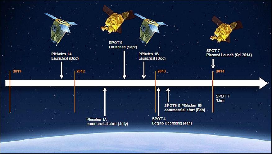
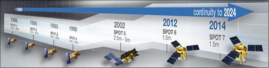
SPOT-6 & -7 are twin commercial Earth observation satellites operated by Airbus Defence and Space (previously as Astrium Services), launched in 2012 and in 2014, respectively. Each satellite has a life-expectancy of 10 years from launch and will continue to image land processes with improvements in end-user operation. The constellation preserves and extends upon the previous SPOT 1-5 missions.
Quick facts
Overview
| Mission type | EO |
| Agency | ASTRIUM |
| Mission status | Operational (extended) |
| Launch date | 09 Sep 2012 |
| Measurement domain | Ocean, Land |
| Measurement category | Multi-purpose imagery (ocean), Multi-purpose imagery (land) |
| Instruments | NAOMI |
| Instrument type | High resolution optical imagers, Data collection |
Related Resources

Summary
Mission Capabilities
The New Astrosat Optical Modular Imager (NAOMI) is the pushbroom imaging system for SPOT-6 &-7 (SPOT-7 has ceased operations since 17 March 2023) and has various applications in land-use management, cartography and national security. The spacecraft has five spectral bands, inclusive of one panchromatic band, one Near infrared band (NIR), and three multispectral bands (Blue, Red, Green). The NAOMI instrument measurements remain consistent with the previous SPOT 1-5 missions, gathering data from parameters such as Earth surface albedo and reflectance, vegetation, and land-surfaces.
Performance Specifications
NAOMI contains two identical Korsch telescopes in silicon carbide that each deliver an aperture of 200mm and a field of regard of ±30°. Each telescope contains a detector with a TDI (Time Delay Integration) matrix of 7000 pixels for the panchromatic channel and four lines of 1750 pixels for the multispectral channel. The panchromatic bands hold a 1.5m to 2.5m GSD (ground sample distance) at nadir in comparison to multispectral bands holding 6m to 10m GSD at nadir. The constellation has spatial resolution of 2m for panchromatic bands, and 8m for multispectral bands with a 60km swath width at nadir using two imagers, or 120km with a single pass mosaic.
The twin satellites are in a sun-synchronous orbit that is inclined at 98.2° and are situated at an altitude of 694km. There is a one-to-five day revisit capability and 6 programming plans per day that cover more than 3 million km2 per day per satellite.
Space and Hardware Components
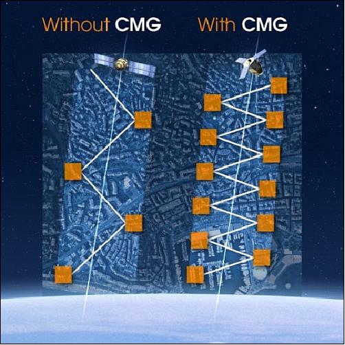
SPOT-6 &-7 maintain the newly developed spacecraft bus AstroBus-L (or AstroSat250) which provides the constellation with mosaics (5 contiguous strips), agility and multiple acquisitions over an area of interest. The platform design meets specific agility standards through the control movement gyroscope (CMG) which gives the satellite superior manoeuvrability in a single passing. This is primarily due to the spacecraft's ability to pitch and roll forward, backwards and sideways by 45°, twice as fast as previous designs.
There is also a ground segment that is divided into two major parts. The CGS (control ground segment) is responsible for the control, command, monitoring and maintenance of the twin satellites in their orbit. The EGS (exploitation ground segment) manages the programming, gathering and analysis of image data to archive and produce image products. An S-band service is utilised and connected to the control ground segment for telemetry data exchanges between SPOT-6 and SPOT-7 (before it ceased operations), which is in accordance with the AstroTerra system - a dynamic network of global communication channels that provide end-users with information regarding satellite monitoring.
SPOT-6 and SPOT-7 (Azersky) Commercial Imaging Constellation
In 2008, Spot Image of Toulouse, France, and partners (EADS Astrium) started an initiative to build a new commercial SPOT mission series, referred to as SPOT-6 /-7, to continue sustainable wide-swath high-resolution observation services as currently provided by the SPOT-5 mission. Having full support from EADS Astrium (Spot Image's majority shareholder), manufacturing of the twin constellation SPOT-6 & -7 was officially announced in mid-2009 by Astrium Services' CEO Eric Beranger. The first launch is scheduled for 2012.
The current (2011) SPOT constellation of two satellites (SPOT-4, and SPOT-5) offers the broadest range of imagery, including, 2.5, 5, 10, and 20 m resolutions. The goal of the new SPOT-6 and -7 series is to guarantee a sustainable operational service to the end users. 1) 2) 3) 4)
From a technical point of view, SPOT-6 & -7 inherited SPOT-5's experience, using new developments from Pléiades-1 & -2 program, as well as from the latest validated technology.
The SPOT-6 & -7 (SPOT-7 has now ceased operations) satellites address the SPOT 5 market with improved characteristics:
• Same image swath of 60 km to maintain a high level of coverage capability
• Better resolution with 1.5 m orthoimage products
• Addition of a blue band to get native natural colour images
• Ultimate satellite agility, enabling to achieve efficiently both collection of large coverage and the collection of individual targets: more than 3 million km2 per day for each satellite
• Reactive tasking: Advanced programming efficiency with up to 6 programming plans per day and per satellite uploads possible to obtain cloud-free imagery
• Daily revisit capability thanks to the phased constellation of SPOT-6 & SPOT-7
• 10-year lifetime for each satellite, assuring data continuity towards 2023.
The SPOT-6/-7 spacecraft operated in tandem until 17 March 2023, when SPOT-7 suddenly failed while in orbit, with the 1 m resolution TerraSAR-X and TanDEM-X radar satellites of DLR, whose commercial data is available to Astrium affiliate Infoterra, and the high-resolution Pleiades-1 and -2 spacecraft. The two Pleiades spacecraft were publicly funded but operate for commercial use by Spot Image. Hence, Spot Image will become the first commercial operator offering two High-Resolution satellites (1.5 m imagery) and two Very High-Resolution satellites (50 cm range of imagery).
Overview
Background
CNES, the French Space Agency, is terminating its SPOT program (which started in 1986 and provided an uninterrupted observation service so far) with an expected retirement of SPOT-5 in the timeframe 2014-15. The SPOT-5 mission (launch May 4, 2002) has already exceeded its nominal design lifetime of 5 years.
In July 2008, EADS's Astrium Services unit has acquired a majority stake in Spot Image S.A. in a move that promises to propel the company to the forefront of the international space imagery market. Astrium agreed to acquire most of the French space agency CNES's holding in Spot Image, giving it an 81% stake in the Toulouse-based optical imaging specialist with five subsidiaries and strategic agreements around the world.
In mid-2009, the Astrium Services Division of EADS is committing to the development of the spacecraft, SPOT-6 and SPOT-7, even though it does not yet have any government funding or pre-sales agreements. The satellites, to be built by Astrium Satellites Division and launched in September 2012 and late 2013, respectively, will be the first ever built on a private basis and mark a watershed in the geospatial information service industry. Although U.S. imaging satellites like Ikonos and GeoEye are funded privately, they rely on guaranteed sales by the National Geospatial Intelligence Agency to finance satellite purchase. 5) 6) 7) 8)
Since early 2011, Spot Image, as well as Infoterra, a German-based radar imaging specialist with affiliates in France, the U.K., Spain and Hungary, is now fully integrated into the "Geo Information Division" of Astrium Services. 9)
The SPOT-6/-7 satellites are funded by Astrium alone; the company owns the data and system (satellites and ground segments). Astrium is also the commercial satellite operator. This is the first time in the remote-sensing industry that satellite development costs have been funded entirely with private funds. 10)

As of January 1, 2014, former EADS rebranded itself as the Airbus Group, with three divisions that include: 11)
- Airbus, focussing on commercial aircraft activities
- Airbus DS (Airbus Defence & Space), integrating the Group's defence and space activities from Cassidian, Astrium, and Airbus Military
- Airbus Helicopters, comprising all commercial and military helicopter activities.
The former Astrium subsidiary was merged into the Airbus DS in late 2013. The new Airbus DS started operating at executive level as of January 1, 2014. The GEO-Information Division of Astrium Services became the program line "Geo-Intelligence", of Airbus DS.
After the consultation process with the works councils, expected to be concluded by mid-2014, the three entities – Airbus Military, Astrium and Cassidian – will be fully integrated and operational at all levels as Airbus DS. 12)
Spacecraft
Spot Image and EADS Astrium in 2007 completed the design work on the SPOT-6 satellite with a launch mass of ~ 800 kg. The spacecraft features CMGs (Control Moment Gyroscopes) instead of reaction wheels to improve pointing manoeuvrability. The satellite's in-orbit design life will be 10 years.
Initially, the SPOT-6 and SPOT-7 program was code-named "AstroTerra" and was an initiative of Spot Image to ensure SPOT service continuity. The timely delivery of the satellites is of prime importance13) for Spot Image, in order to guarantee, without interruption, the level of service expected by its customers. 14) 15) 16) 17)
Parameter / Spacecraft | SPOT-5 | SPOT-6 / -7 |
Launch | May 4, 2002 | SPOT-6 on Sept. 9, 2012 |
Launch mass | 3000 kg | 714 kg (including 60 kg for payload and 80 kg of propellant) |
Spacecraft bus | SPOT MK2 (extended version) | AstroBus-L (also known as AstroSat-250 or AS250) |
Spacecraft size | Body: 3.1 m x 3.1 m x 5.7 m | Body: ~ 1.55 m x 1.75 m x 2.7 m |
Spacecraft design life | 5 years | 10 years |
Main sensor | 2 x HRG (High Resolution Geometric) | 2 x NAOMI |
Spatial resolution | Pan: 5 m (2.5 m supermode), | Pan: 2 m, |
Swath width | 60 km (1 imager) | 60 km (2 imagers) |
Daily image acquisition capability in HR mode | up to 3 x 10⁶ km2/ day in operation | up to 3 x 2 x 106 km2/ day in operation |
Spacecraft agility | Roll only (mirrors), 30º in 8 s | All axes platform, 30º in 12 s |
Single pass stereo capability | Only through HRS | Single pass stereo and tri-stereo |
Geolocation | 50 m without GCP | 35 m without GCP; < 10 m with Ref3D |
Just-in-time tasking capability | No (1 mission plan/day) | Yes (up to 6 mission plans /day) |
Additional payloads | HRS, Vegetation, DORIS | No |
Revisit capability |
| 1 (45º) to 5 days (30º) |
Orbit | 832 km, sun-synchronous, | 695 km in quadratic phase with Pleiades satellites |
The SPOT-6/-7 satellites are based on the platform family named AstroSat-250 (also referred to as AstroBus-L), i.e. an upgraded version derived from the FormoSat-2 and THEOS missions, featuring CMGs (Control Moment Gyros) as actuators. This technology will provide the satellites with an unrivalled agility, allowing single-pass stereo or tri-stereo, mosaics (up to 5 contiguous strips), as well as multiple acquisitions over a given target area.
AstroBus-L description (Ref. 14):
The AstroBus-L is a standard, modular, ECSS (European Cooperation for Space Standards) compatible satellite platform compatible with an in-orbit lifetime of up to 10 years, with consumables sizeable according to the mission needs. The platform design is one-failure tolerant and the standard equipment selection is based on minimum Class 2 EEE (Electrical, Electronic, and Electromechanical) parts, with compatibility to Class 1 in most cases. It is implemented on AstroTerra (SPOT-6/-7), SEOSat/Ingenio of Spain, GMES/Sentinel-2 of ESA, EarthCARE of ESA, and the Kazakhstan HR imaging satellite of KGS (Kazakhstan Gharysh Sapary), currently referred to as ERSSS (Earth Remote Sensing Space System).
The AstroBus-L platform is designed for direct injection into LEO (Low Earth Orbit). Depending on the selection of standard design options, AstroBus-L can operate in a variety of Low Earth Orbits at different heights and with different inclinations.
Note: The AstroBus-L platform is also referred to as AstroSat-250 (or AS250). The AstroSat-250 standard architecture reflects the large experience gained by Astrium in many Earth Observation missions. AstroSat-250 combines heritage with flexibility for customisation. Through optimization of reuse, it helps to reduce program risk and to achieve reliable schedule and cost commitments. It ensures high quality and robustness due to the continuous application of proven solutions and it guarantees the continuity of engineering skills.
Both satellites have drawn on technological and operational innovations conceived for some of them for the Pleiades constellation (CMG, FOG) and for others on Astrium's product lines. The satellites are in particular based on an Astrium AS250 new generation avionics based on a standard core avionics (computer, data handling unit, software) and state-of-the-art technologies (agile gyro-less attitude control concept, ...), and integrated on a small-sized structure together with an optical instrument based on the NAOMI product line.
Both satellites are agile due to their CMGs. Even if today many satellites are manoeuvrable, all do not swing and re-target at the same speed. CMGs allow the satellites to pitch and roll forward, backwards and sideways up to 45° very quickly - twice as fast as earlier designs such as Momentum Wheels. Why does the user care? Because it increases the number of images that can be collected during the same pass. In a shell, collections opportunities are more numerous, scheduling conflicts between contiguous requests are vastly reduced, and then, the average acquisition window is much narrower. Icing on the cake, the acquisition on the same pass of several targets at the same latitude becomes possible.
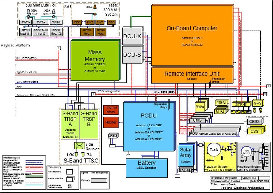
The core of the AstroBus-L electrical platform is the redundant OBC (On-Board Computer). The OBC includes processing, reconfiguration and timing functions while the complete I/O system is allocated in a separate physical unit, the RIU (Remote Interface Unit), which enables mission customization. The backbone for the onboard communication is formed by two MIL-STD-1553 buses, one serving the platform and one serving the payload. Optional SpaceWire interfaces allow for the transmission of data at high rates between the OBC and e.g. special payloads.
The LEON3-FT (Fault Tolerant) microprocessor, namely the SCOC3 (Spacecraft Controller On-a- Chip), is being used as OBC. SCOC3 has been developed at EADS Astrium SAS; it is manufactured by Atmel.
A standard S-band TT&C system with full spherical coverage in uplink and downlink is used for satellite command reception and telemetry transmission. Ciphering functions are available either integrated within the OBC or in form of an add-on unit to the OBC called DCU.
ADCS (Attitude Determination and Control Subsystem)): The enhanced 3-axis stabilization attitude control system is based on a set of 4 RW (Reaction Wheels) for fine-pointing with 3 MTQ (Magnetic Torquers) for off-loading. In case of very high agility requirements, the reaction wheels are replaced by Astrium patented CMGs (Control Moment Gyros).
Attitude and orbit measurement is performed with a GPS and a Star Tracker (STR) for nominal operation, providing a pointing accuracy of up to 500 µrad (3σ) and a pointing knowledge of up to 30 µrad (3σ), depending mainly on STR accommodation and alignment accuracy. While standard precise attitude control is performed without the support of a gyro, an optional inertial measurement unit can be added for attitude control improvement. On-board orbit determination accuracies of < 10 m (1σ) are achieved, if the standard 1-frequency GPS design is applied. The 2-frequency GPS option provides on-board orbit determination accuracies of < 3 m (1σ).
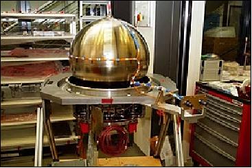
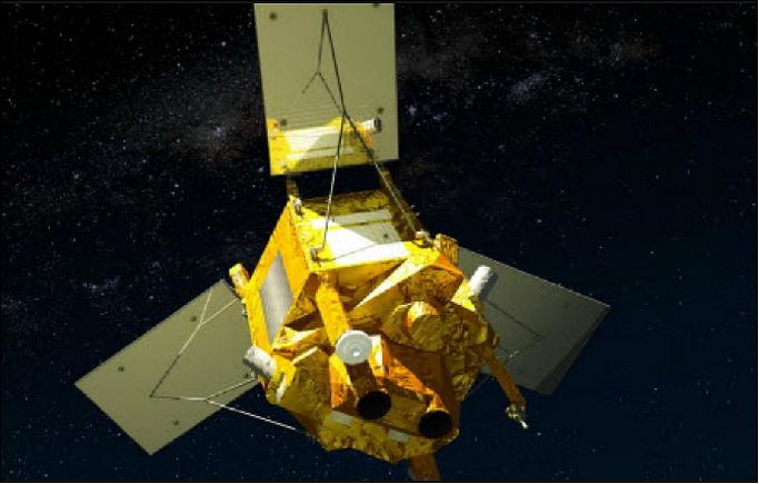
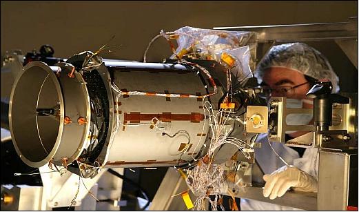
Legend to Figure 4: The SPOT-6 spacecraft is the firat EO mission to utilize Sodern's new generation HYDRA star tracker for guidance and navigation. With HYDRA, Sodern is offering a multi-head design which separates the optical head from the centralized processing unit. This eases the thermal control of the optical heads and allows continuous attitude measurement, whether the satellite is facing Earth, the Sun or other bright objects.
Safe mode attitude sensing is based on a Magnetometer (MAG) / Sun Sensor (BASS) system or optionally a Magnetometer / Coarse Earth Sun Sensor (CESS) system. This provides two optional Safe mode attitude control principles:
1) Sun oriented, magnetic field spin controlled, or
2) Earth oriented.
Propulsion system: A mono-propellant propulsion system is implemented to allow for orbit maintenance and optionally for rapid rate damping during initial acquisition in case of the Earth oriented safe mode. Different tank sizes and thrusters configurations are available to cover specific mission needs.
EPS (Electrical Power Subsystem): The EPS is built around an unregulated 28 V Power Bus. GaAs triple junction solar cell based arrays, which are either composed of standard panels or have to be tailor designed to suit mission needs, are used for power generation. Power control and distribution functions are combined in the PCDU (Power Control and Distribution Unit).
For missions with a low power demand (< 1200 W) and only slight variations in solar array illumination conditions, a standard PCDU with shunt regulation system is foreseen. Higher power demand can be satisfied with MPPT (Maximum Power Point Tracker) regulation based PCDU, which can be selected from a set of different peak power values. Sufficient FCLs and LCLs in different power classes are provided for platform and payload power distribution and protection. Furthermore, a comfortable amount of heater switches and redundant release actuators is available. Electrical energy is stored in Li-ion batteries, for which a large range of different capacities is available.
The AstroBus-L software is based on a modular architecture with a standard mission and hardware independent core consisting of the RTEMS operating system and the Astrium CDHS (Core Data Handling System). A library of reusable hardware-and mission dependent software elements exists which can be used as basis for construction of individual mission customized software versions. The process of mission specific software customization and development is done in compliance with ECSS E-40 and Q-80.
An essential feature of AstroBus-L is the robust standard FDIR (Failure Detection, Isolation and Recovery) concept, which is hierarchically structured and can easily be adapted to specific mission needs.
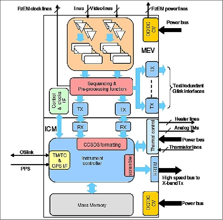
Payload data are being stored in NAND flash memory technology SSR (Solid State Recorder) based on integrated CoReCi (Compression Recording and Ciphering) units of Airbus DS, available at various capacities ranging from 1 Tbit to ~ 10 Tbit. Options exist for inclusion of compression and encryption functions within the CoReCi. Several different standard algorithms are available for this purpose. 18)
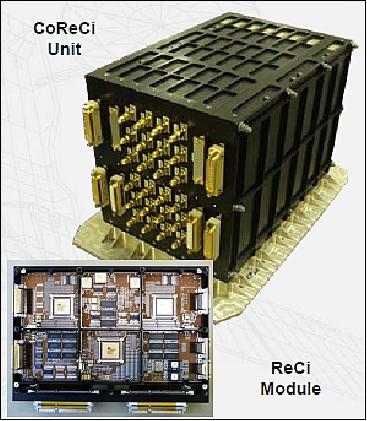
CoReCi implementation parameters for SPOT-6: 19)
- Modular architecture adaptable to various data rates and capacities
- Input data rate up to 1.4 Gbit/s
- Capacity 850 Gbit (EOL) with Flash technology
- Embedded Wavelet Image Compression with MRCPB algorithm
- Ciphering based on AES (Advanced Encryption Standard) algorithm with 127 x 128 bit ciphering keys
- Data Formatting according to CCSDS ESA Packet Telemetry Standard
- Instrument mass: 14 kg
- Power consumption 75 W during simultaneous data record / data compression / data replay.
CoReCi on SPOT-6 represents the first commercial use of Flash storage technology in an on-board PDHU (Payload Data Handling Unit).
RF communications: The standard for downlink of payload data is a 300 Mbit/s 2-channel cold redundant X- band. The data transmission system uses QPSK modulation. A single Isoflux antenna provides the necessary ground coverage. Optionally, other systems can be incorporated in case of higher downlink data rate needs. Encryption of downlink data can be implemented as option. A number of different basic mechanical standard configurations are available which can be used as foundation for mission customization in many typical applications. The TT&C data are transmitted in S-band.
Launch
SPOT-6 Launch
The SPOT-6 spacecraft was launched on Sept. 9, 2012 on a PSLV vehicle (flight PSLV-C21) from SDSC (Satish Dhawan Space Center) SHAR on the east of India. 20) 21)
In April 2012, Astrium SAS signed a launch agreement with Antrix Corporation Ltd. (the commercial arm of ISRO). 22)
The secondary payload on this flight was:
• PROITERES, a nanosatellite (15 kg) of the Osaka Institute of Technology, Osaka, Japan
The nominal launch of SPOT-7 is planned for 2014.
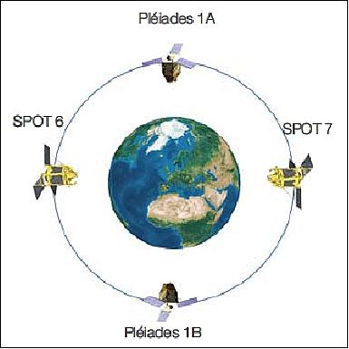
Orbit: Sun-synchronous circular orbit, altitude = 694 km, inclination = 98.2º, LTAN = 22:00 hours. When SPOT-7 is in orbit, both spacecraft will be deployed into the same orbital plane phased at 180º.
Note: Astrium Geo-Information Services is the civil operator of the Pleiades constellation (Pleiades-1A and -1B) as well as the operator of the SPOT-6 and SPOT-7 constellation. When SPOT-7 is launched in 2014, there will be 2 x 2 satellites, a true constellation with all spacecraft in the same orbital plane, coherently operated (90° one from the other on the same orbit) through a single interface (Ref. 55).
SPOT-7 Launch
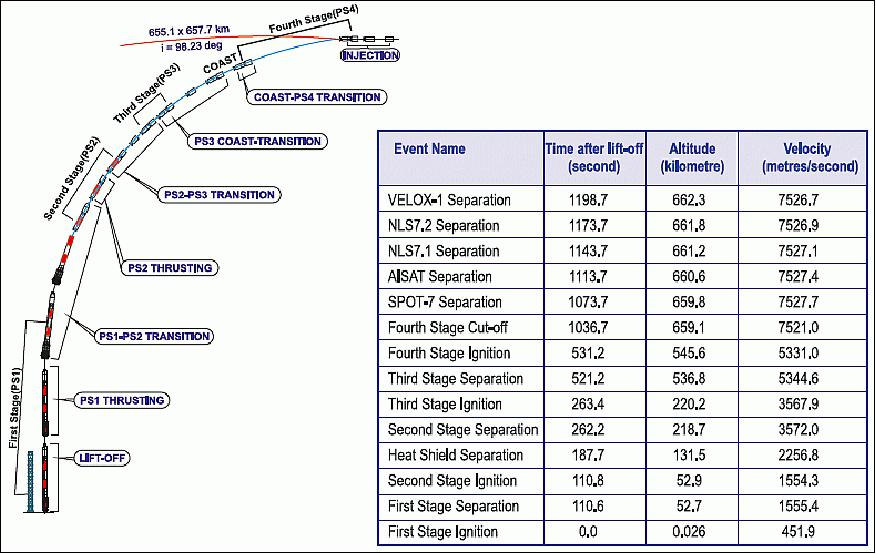
Launch: The SPOT-7 satellite was launched on June 30, 2014 (04:22:00 UTC) on ISRO's PSLV vehicle (flight PSLV-C23) from SDSC (Satish Dhawan Space Center) SHAR on the east coast of India. 23) 24) 25)
The satellite ceased operations on 17 March 2023, due to a failure while in orbit, between 7:34 pm and 10.48 pm UTC.
Insertion orbit: Sun-synchronous circular orbit, altitude = 660 km, inclination = 98.23º, LTAN = 10:00 hours.
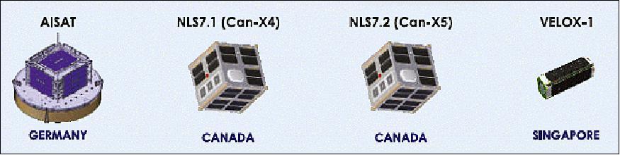
The secondary payloads on this flight were:
• CanX-4 and CanX-5, a pair of identical nanosatellites (each of 15 kg) of UTIAS/SFL (University of Toronto, Institute for Aerospace Studies/Space Flight Laboratory), Toronto, Canada.
• AISAT (Automatic Identification System Satellite), a technology demonstration nanosatellite (14 kg) of DLR (German Aerospace Center). 26)
• VELOX-1 is a 3U CubeSat with a mass of 4.5 kg of SaRC (Satellite Research Center) at NTU (Nanyang Technological University), Singapore.
The SPOT-7 spacecraft joined the orbit in which its twin, SPOT 6, and the very-high-resolution observation satellites Pleiades 1A and 1B are located, and was positioned at 180º in relation to SPOT 6 (Figure 13). After SPOT-7 had undergone a period of tests in orbit, Airbus Defence and Space's optical constellation was at its full operational capacity.
In addition, PSLV-C23 hosts one attached payload, the AINS (Advanced Inertial Navigation System) which was riding uphill with the launcher, making navigation measurements during ascent that are purely used for the validation of the system for potential use on Indian launch vehicles in the future. Data provided by AINS was not used to navigate the PSLV launcher on this flight and was collected for downlink to the ground to examine the accuracy and performance of the new navigation system that was smaller in size than the old unit, but delivered a higher accuracy (Ref. 24).
Mission Status
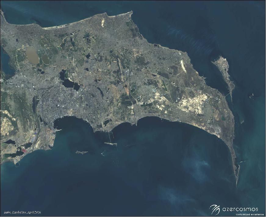
• March 17, 2023: Azerbaijan’s space agency, Azercosmos, acknowledged the failure of its Azersky optical Earth observation satellite, also known as SPOT-7, but said it would continue to serve customers with the twin Spot 6, which is owned by Airbus Defence and Space. The Azersky/SPOT-7 satellite suddenly failed in orbit between 7:34 pm and 10.48 pm UTC on March 17. 69)
• January 30, 2018: Airbus has introduced near real-time satellite imagery capabilities and a 24/7 Emergency Image Delivery Service, utilizing the KSAT polar ground station in Svalbard, Norway. This enables rapid retrieval of Pleiades and SPOT constellation images at every orbit, ensuring ultra-fast deliveries worldwide within an average of two hours after acquisition. The service aims to provide immediate support during unplanned events, crises, or disasters, offering timely and accurate satellite images to assess damage and aid in mitigating the impact. With a dedicated team of experts, the 24/7 service enhances Airbus' responsiveness and flexibility in delivering critical satellite data to customers and partners. 27)
• August 28, 2017: Airbus Defence and Space has collaborated with GIS mapping engine operator Satshot to offer high-resolution SPOT-6/-7 satellite data covering the corn and wheat belt in the continental United States. Integrated into Satshot's cloud-based GIS mapping engine, SPOT-6/-7 data with 1.5 m high resolution provides valuable information for agricultural applications, including crop health monitoring, NDVI analysis, crop damage assessment for insurance, land use sustainability management, and Precision Ag VRT. This collaboration aims to enhance efficiency and decision-making in the agricultural industry by providing near real-time solutions and insights to farmers and agribusinesses. 28) 29)
• March 2017: Airbus Defence and Space maintains full access to the capacities of the SPOT-6 and SPOT-7 satellites and continues to provide unchanged commercial services to its global customers. The SPOT-6 and SPOT-7 satellites operate as a true constellation, orbiting on the same trajectory with a 180º phase difference, ensuring daily revisit capacity to any point on the globe. While Azercosmos is the preferred distributor for SPOT-6 and SPOT-7 data in the Caucasus and CIS countries, Airbus DS remains the distributor for the rest of the world. Both parties independently manage customer tasking requests within their designated regions, coordinating on high-priority requests outside their areas of responsibility. The arrangement allows for coordinated exchange of imagery on a case-by-case basis, and SPOT-7 is marketed by Azercosmos as Azersky without changes for Airbus Defence and Space customers. 32)
• February 14, 2017: Airbus Defence and Space has introduced new options for geometric and radiometric processing for SPOT and Pléiades imagery. These options, including Projected, Reflectance, and Display choices, are now available through all ordering channels, including Customer Service and GeoStore. 33)
• September 2016: The Kiribati archipelago, comprising 33 atolls, reef islands, and a raised coral island, is depicted in an image acquired by SPOT 6/7 on September 29, 2015. Situated in the central Pacific, these islands cover 3.36 million km2 with a population just over 100,000. Uniquely positioned in all four hemispheres, Kiribati faces significant vulnerability to climate change, particularly rising sea levels, which pose a potential threat to the islands and their inhabitants. 35)

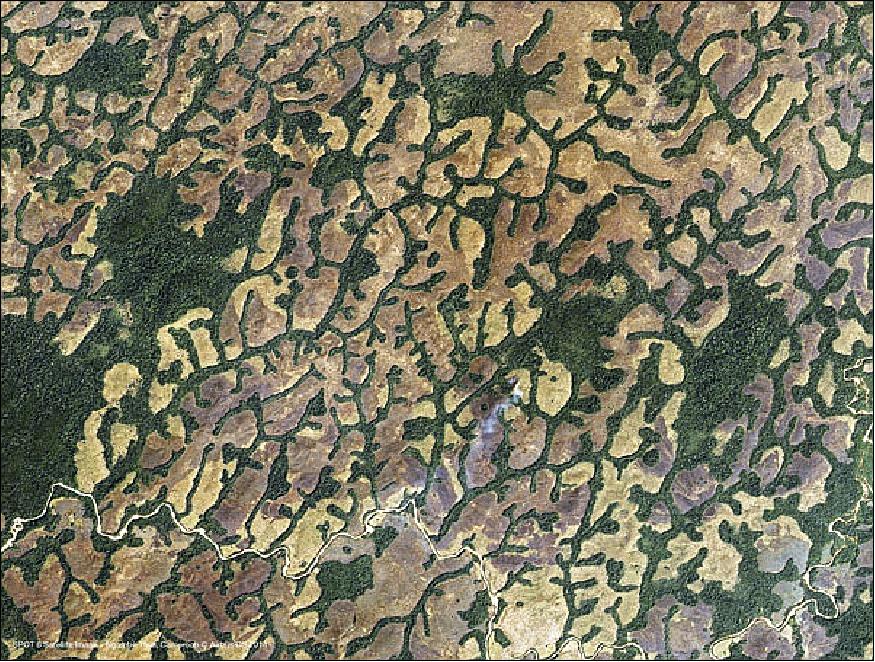
• Feb. 2, 2016: The image captured on January 9, 2015 (Figure 17), illustrates the municipality of Ngambè Tikar in Cameroon, situated in the central part of the country on the Tikar plain. Marked by a landscape of forests and savannas, this region plays a vital role in Cameroon's agriculture due to its abundant rainfall and humid climate. 36)
• August 18, 2015: The SPOT-6 and SPOT-7 DRS (Direct Receiving Station) installed at the SANSA (South African National Space Agency) premises by Airbus Defence and Space, has allowed to cover the entire country (1 221 000 km2) at 1.5 m resolution in just 3 months. The DRS has been upgraded in 2014 to receive the SPOT-6 and SPOT-7 data. 37)
• April 15, 2015: Since the launch of the Pleiades-A satellite in late 2011, Airbus Defence and Space Electronics has played a crucial role in enhancing the efficiency of Earth Observation missions through the implementation of GN&C (Guidance, Navigation, and Control) equipment. This technology, exemplified by the Pleiades-A satellite and later extended to Pleiades-B, SPOT-6, and SPOT-7, incorporates agility capabilities based on Control Moment Gyroscope (CMG) technology. The cumulative life span of the four satellites in orbit has surpassed 35 years. Building on the success of CMG, Airbus Defence and Space has developed the NEWTON agility package family, offering subsystems that enable the seamless integration of actuators and are suitable for a diverse range of satellite platforms, from 500 kg to over 2000 kg. 38)
• April 10, 2015: ESA has made various satellite image archives, including SPOT-1 to 5, SPOT-6 and -7, Pleiades, and SPOTMAPS 2.5, available to the scientific user community. These datasets, provided at different processing levels, encompass both historical archives and new acquisitions, with offerings such as stereo and tri-stereo modes for SPOT-6 and -7 and Pleiades. Researchers and developers can access these resources free of charge by submitting project proposals through ESA's Earth Online Portal, supporting scientific research and application development in Earth observation. 39)
Mission operators | SPOT 1-5: CNES |
Launch dates | First launch: 22 February 1986 |
Orbit altitude | SPOT 1-5: 832 km |
Orbit type | Sun-synchronous |
Repeat cycle, spatial resolution, swath width | 26 days, from 20 m to 1.5 m, 60 km |
Onboard sensors provided under ESA's TPM (Third Party Mission) program | HRV, HRVIR, HRG and NAOMI |
All of the SPOT satellites provide imagery in panchromatic and multispectral bands with a swath of 60 km. SPOT-6 and SPOT-7, will assure data continuity through to 2024. | |
• December 2, 2014: Airbus Defence and Space has achieved a significant milestone with the commercial launch of SPOT-7, completing its optical satellite constellation, which includes SPOT-6, Pleiades-1A & -1B, TerraSAR-X, and TanDEM-X. This comprehensive constellation offers a range of Earth-imaging data in multiple resolutions and spectral wavelengths. A strategic cooperation agreement has been signed with Azercosmos, the Azerbaijani satellite operator, involving the transfer of ownership of SPOT-7 to Azercosmos and joint operations with SPOT-6, creating a constellation with a combined acquisition capacity of six million km2 per day. The collaboration includes training Azerbaijani professionals in optical satellite operations and commercializing Earth observation services. 42) 43) 44) 45)
• October 1, 2014: SPOT-7 has successfully completed key milestones in its calibration phase, affirming its excellent image quality performance. Since August 5, 2014, the collected images have been cataloged, and the start of commercial operations is imminent. With SPOT-6 and Pleiades-1A/1B, SPOT-7 is poised to offer new application opportunities, delivering fresh images with unprecedented speed. 46)
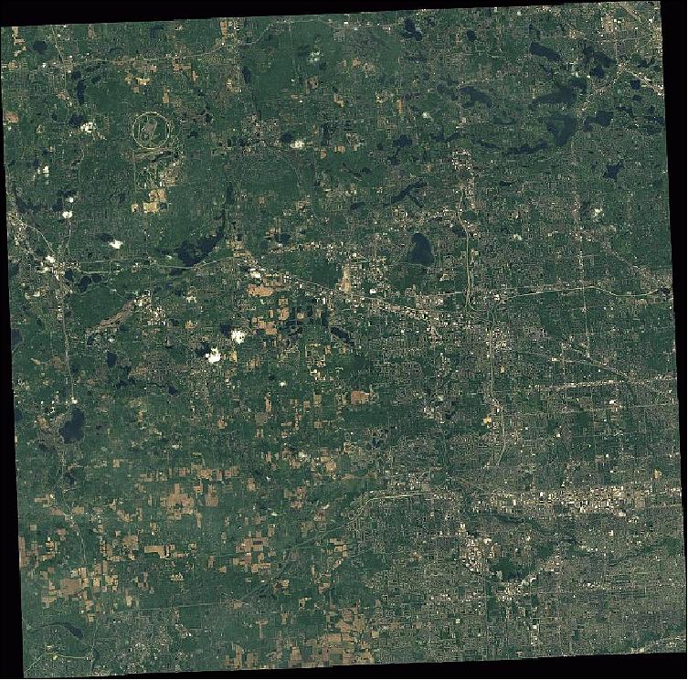
• July 4, 2014: The SPOT-7 satellite successfully acquired its first images within three days of launch, marking a significant milestone for the SPOT-6/7 constellation. This constellation, now fully operational, enhances capabilities and performance compared to its predecessor, SPOT-5. Offering higher resolution, increased programming reactivity, and a substantially higher daily image acquisition volume in both monoscopic and stereoscopic modes, the new constellation aims to surpass the capabilities of SPOT-5, which is scheduled for decommissioning in early 2015. Sample images from SPOT-7 are showcased in Figures 19 and 20. 47)

• June 30, 2014: The SPOT-7 satellite separated from the rocket 18 minutes after launch and went into a 660 km orbit; the other four secondary satellites were deployed over the next two minutes, according to ISRO (Indian Space Research Organization). 48)
• May 2014: Airbus Defence and Space has achieved a significant milestone with the Solid-State Recorder (SSR) utilizing flash memory on the SPOT-6 satellite, surpassing 20 months of successful operation in orbit. As the first commercial satellite to deploy this technology, the flash SSR has demonstrated superior storage capacity at a reduced operating cost compared to SDRAM. Notably, the device has proven its reliability and efficiency in Earth observation missions, maintaining a flawless track record on SPOT-6. Furthermore, the flash SSR has met the stringent qualification standards set by both NASA and ESA, affirming its advanced capabilities in space applications. 49)
• March 28, 2014: Airbus Defence and Space has achieved a significant milestone with the Solid-State Recorder (SSR) utilizing flash memory on the SPOT-6 satellite, surpassing 20 months of successful operation in orbit. As the first commercial satellite to deploy this technology, the flash SSR has demonstrated superior storage capacity at a reduced operating cost compared to SDRAM. Notably, the device has proven its reliability and efficiency in Earth observation missions, maintaining a flawless track record on SPOT-6. Furthermore, the flash SSR has met the stringent qualification standards set by both NASA and ESA, affirming its advanced capabilities in space applications. 51)
• March 28, 2014: SPOT-6 has demonstrated exceptional location accuracy, surpassing satellite requirements during its commissioning phase in 2012. The initial measurement of 19.3 m CE90 @30º was already nearly twice as accurate as the satellite requirement of 35 m CE90 @30º. After one year of refinement and temporal drift calibration, the current performance as of March 2014 has improved significantly, achieving a location accuracy of 11.9 m CE90 @30º—nearly three times better than the satellite requirement. Planimetric accuracy assessments, including evaluations on reference sites and auto-calibration, further confirm the high precision of SPOT-6 imagery. 52)
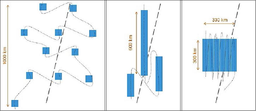
• October 2013: The agility of SPOT-6 (and -7) satellites enables a diverse range of acquisition scenarios in a single pass (Figure 23). These scenarios include capturing individual scenes (left), long strips (center), contiguous strips (right), and stereo collections for 3D modeling. The tri-stereo capability, facilitated by the satellites' agility, involves acquiring a third image at nadir, enhancing elevation data accuracy. Notably, the 12-bit pixel depth of SPOT-6/7 contributes to improved image quality, allowing for better detection of objects in shadows and increased capability to discern subtle nuances in various environments. Furthermore, the satellites exhibit enhanced intrinsic geolocation accuracy, exceeding 20 m CE90 for primary products and achieving 10 m for automatic orthos, supporting high-precision mapping applications at different scales. (Ref. 17):
• July 2013: SPOT-6 has successfully undergone testing by the Joint Research Centre (JRC), the European Commission's science service, and has been integrated into the MARS-CAP (Monitoring Agricultural Resources-Common Agricultural Policy) program since July 1, 2013. The MARS-CAP program, established by the European Union, utilizes satellite imagery, including SPOT-6, to survey agricultural land across Europe for verifying declarations submitted by farmers regarding cultivated and fallow land. SPOT-6, with its 1.5 m resolution, blue spectral band for natural color images, precise localization, and exceptional agility, enhances the performance of the MARS-CAP program, allowing efficient mapping of extensive areas within a short timeframe. Astrium Services has collaborated with the European Commission for two decades in implementing the Common Agricultural Policy. 54)
• January 2013: SPOT-6 has been officially declared operational following the successful completion of technical commissioning. The satellite's functions and performance are nominal, with some aspects surpassing specifications. Rigorous testing of the sensor's agility has been conducted, covering scenarios such as imaging large areas in a single pass, consecutive long strip acquisitions, and target acquisitions. The system is fully operational, achieving daily acquisitions close to its maximum capacity of 3 million km2. Managed by Astrium GEO-Information Services, SPOT-6 has demonstrated exceptional performance, imaging over 100 million km2 in the last two months, even without operating at full capacity. Control of the satellite is supported by Astrium Satellites. 56)
• October 2012: Astrium Services and the Istanbul Technical University (ITU) signed two agreements in Istanbul , to develop high-resolution and large-area coverage services in Turkey, notably for agriculture. The agreements cover a SPOT New Generation receiving station and reception of data from SPOT-6 and SPOT-7, as well as an extension for SPOT-5 data. 57)
• September 22, 2012: SPOT-6 has successfully reached its designated orbital slot, completing the initial positioning phase with a review on October 12, 2012. During this phase, an extensive analysis of the in-orbit status of the satellite's subsystems was conducted, confirming the nominal functioning of all systems. Fuel consumption has been carefully managed in accordance with the satellite's planned 10-year operating lifetime. 58)
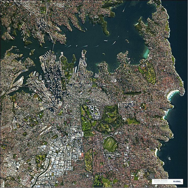
• September 12, 2012: Three days after launch, SPOT-6 acquired its first image of the Bora Bora atoll (French Polynesia), part of the Society Islands in the Pacific Ocean. The pansharpened image (Figure 25) has a resolution of 1-5 m 59) 60)

Legend to Figure 25: Bora Bora is an atoll island in the wind which means "first born." The island is surrounded by a large lagoon and a fringe of coral reef. The center is occupied by an extinct volcano.
Sensor Complement
NAOMI (New AstroSat Optical Modular Instrument)
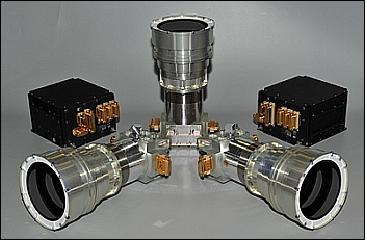
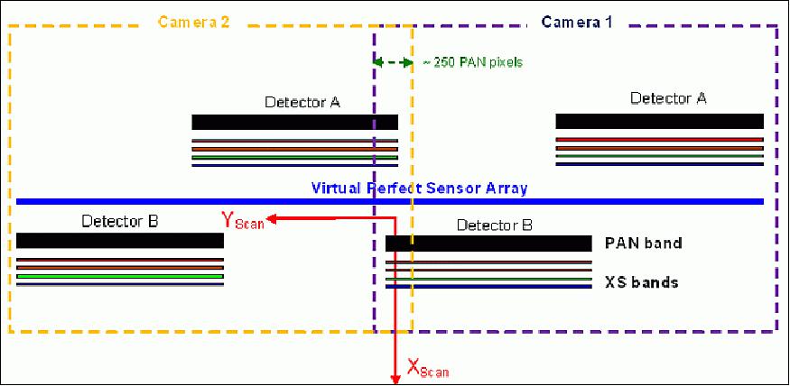
NAOMI is a product line of high-resolution imagers designed and developed at EADS Astrium SAS. Several versions of the NAOMI instrument have already been developed with a GSD from 1.5 m to 2.5 m, and swath widths from 10 km up to 60 km. All of them are based on the same telescope concept implementing one or several focal planes units in the same camera, and even two cameras in the same instrument as for the SPOT-6 & SPOT-7 program.
NAOMI instruments can be embarked on small platforms (Myriade class) or larger platforms (Astrosat-250). The IEU (Instrument Electronics Unit) can accommodate internal mass memory functions or can be coupled with high capacities mass memories like CORECI equipment also developed by Astrium SAS.
The main building blocks of the instrument are: 61)
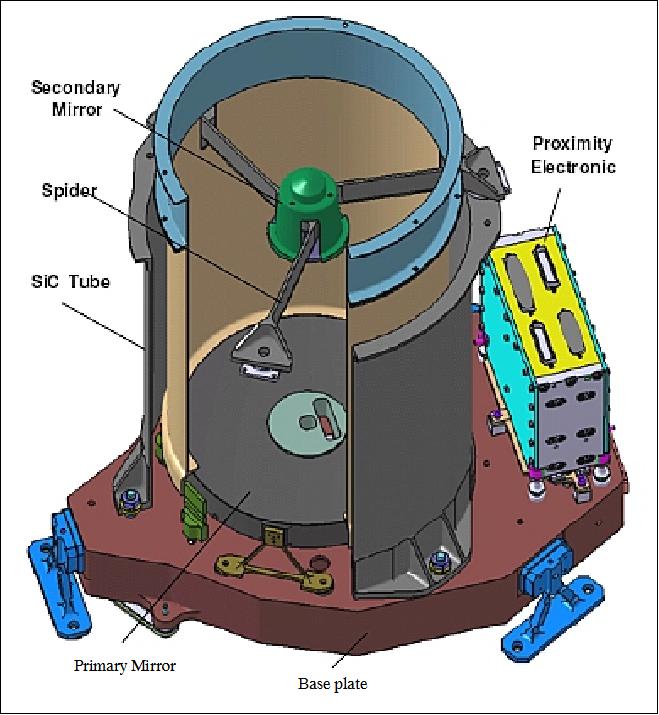
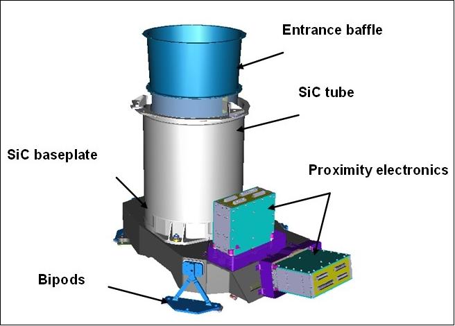
• A highly stable, light and compact telescope built in SiC material, with a simple thermal control.
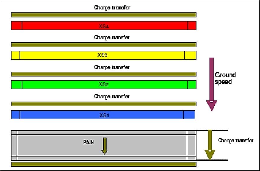
• A focal plane, embedding TDI (Time Delay Integration) detector, a PAN CCD and four XS (multispectral) detectors equipped with strip filters and coupled with front end electronics. The TDI implementation exhibits an outstanding MTF (Modulation Transfer Function) servicewith an extremely low power consumption. This allows significantly loosening of optical requirements at the telescope level, while keeping the same overall optical quality at system level; in other words, the same optical quality can be reached from smaller and much lighter telescopes. Therefore more performance can be obtained from smaller satellites.
• Back-end electronics, including video Electronics, data storage and services adapted to the mission specificities. The modular video chains are capable of operating at different frequencies up to 15 Msample/s, so that the same hardware can be easily tuned to serve ground resolutions ranging from 0.5 m to say 10 m. The swath width can easily be adjusted by butting together several detectors and associated modular video chains, thus fulfilling the requirements of the most demanding customers.
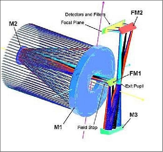
The telescope is based on a Korsch combination, offering a simple, compact concept. The detector, space qualified, includes on the same die one TDI matrix of 7000 pixels for the panchromatic channel, and four lines of 1750 pixels for the multispectral bands. The detector exhibits excellent characteristics that significantly contribute to the instrument very high optical performance.
The optical assembly is based on a Korsch-type telescope including three aspheric mirrors and two folding mirrors.
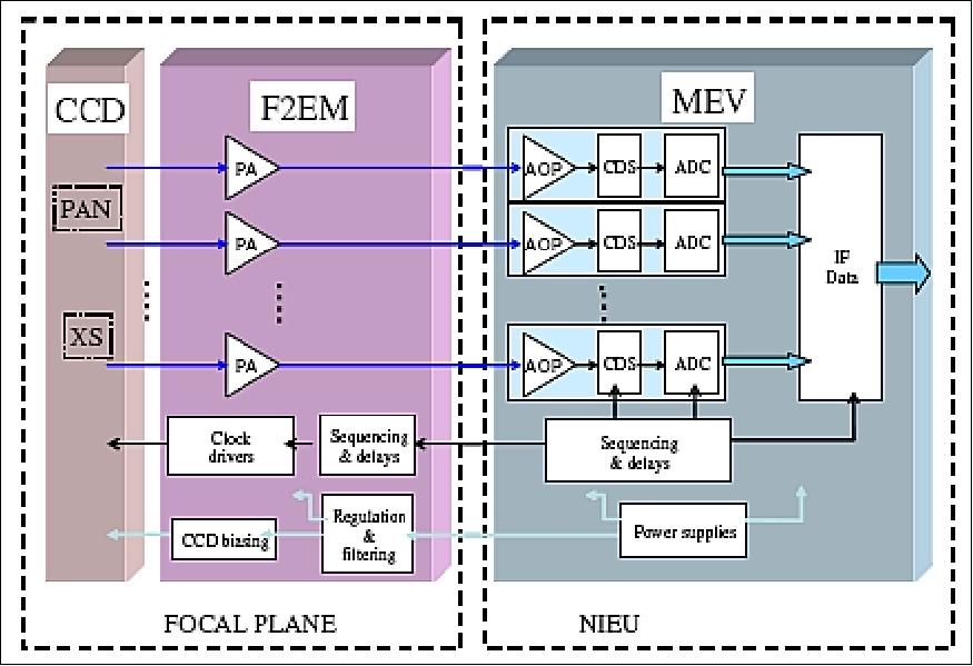
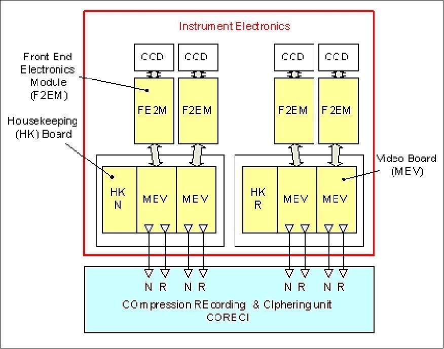
The detection chain is made of three main parts: the detectors, the Front End Electronics Module (F2EM) and the Video Electronics (MEV) which are part of the IEU (Imaging and Electronics Unit). The PAN + XS focal planes are the heart of the detection chain.
Focal plane is based on a customized high performance detector architecture developed by e2v for Astrium (proprietary architecture). It takes benefit of all the heritage and skills acquired in CCD architecture definition and in operating with the ultimate conditions of speed and performances. The result of this customization offers an unrivalled level of integration and performances. All the stringent constraints of dynamic range optimization and power consumption reduction have been mastered with less than 1 watt detector dissipation.
The Front-End Electronics Module (F2EM) encompasses all the functions to be implemented close to the detectors. Mounted inside the FPA (Focal Plane Assembly), it provides the detectors with all the necessary biasing and clocking signals and performs preamplification and transmission of the video signal to the MEV.
The MEV (Module Electronique Video) is the backend part of the NAOMI detection electronics. The MEV provides the F2EM with the primary power supplies and clocks necessary to front-end operation. The video signal from the F2EM is received, adapted and digitally converted to 12 bit in the MEV. The resulting data, rounded down to 10 useful bits, are then transmitted to the digital functions of the NIEU to be real-time processed and stored into the mass memory for further downlink.
Instrument type | Pushbroom imager |
Optics | - Korsch telescope in SiC (Silicon Carbide) |
Spectral band (Pan) | 0.45-0.75 µm |
MS (Multispectral bands), 4 | Blue: 0.45-0.52 µm |
GSD (Ground Sample Distance) | PAN: from 1.5 m to 2.5 m at nadir |
Detectors | N x silicon area arrays with 7000 pixels PAN, 1750 pixels in each MS band |
TDI (Time Delay Integration) | The PAN band offers TDI services for SNR improvement of the signal |
Swath width | - From 10 km to 60 km at nadir depending on GSD and number of detectors 63) |
FOR (Field of Regard) | ±30º (spacecraft tilting capability about nadir for event monitoring) |
Data quantization (dynamic range) | 12 bit |
Legend to Table 4: For a given mission, the swath is fixed (60 km for SPOT-6/-7). The range from 10 to 60 km features the swath value for different missions using a NAOMI instrument. 62)
The same logic applies to the variable parameter of GSD in Table 4: The GSD is fixed for a particular mission (the ranges feature the values for different missions using a NAOMI instrument). For SPOT-6/-7, the GSD for PAN = 2 m and for MS = 8 m.
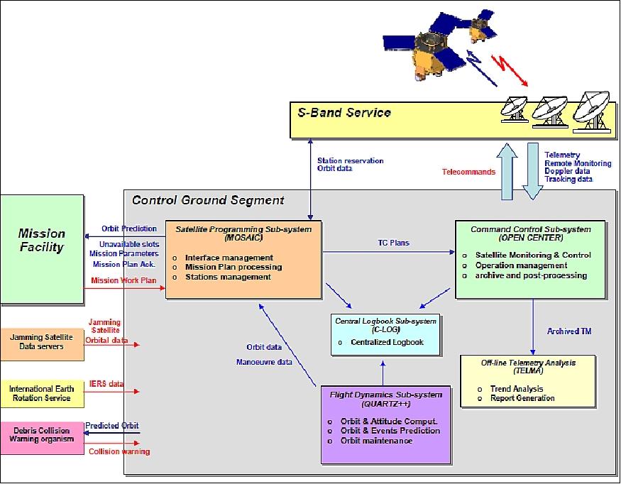
Ground Segment
The overall control ground segment architecture is based on a well-mastered and efficient design which has been used and improved on several Astrium export programs - like the ground segments for the missions: THEOS (Thailand), AlSat-2 (Algeria), and SSOT (Chile). 63) 64)
The SPOT-6/-7 (AstroTerra) architecture comprises a ground segment divided into two major parts:
• The CGS (Control Ground Segment), in charge of controlling, commanding and monitoring the SPOT-6 and SPOT-7 satellites on their orbit, and maintaining the orbit. The objective of CGS is to gather all the requested means for managing the satellite configuration and for supporting the satellite maintenance.
• The EGS (Exploitation Ground Segment), in charge of programming the satellite mission plan and ingesting the image data and processing it in order to produce, archive and deliver the SPOT-6 and SPOT-7 image products.
The CGS is connected to a full scale S-band service, providing access to one or several S-band stations for telemetry and telecommand data exchanges with the SPOT-6 and SPOT-7 satellites. This S-band service will include at least one polar station, so as to provide maximum access to the satellites.
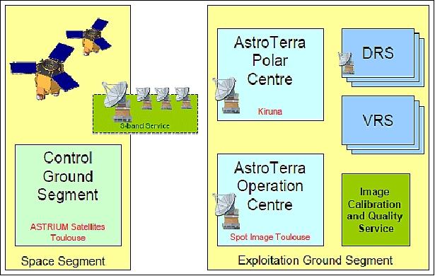
The AstroTerra system is composed of:
• The Space Segment in charge of collecting the imagery data and including :
- Spot 6 and Spot 7 observation satellites operating on a Low Earth Orbit
- The AstroTerra Control Ground Segment, located at the Astrium Satellite premises, Toulouse, France
• The customer Operator Segment also called Exploitation Ground Segment made of:
- A network of AstroTerra DRS (Direct Receiving Stations)
- An AstroTerra Polar Center, located in Kiruna, Sweden
- The AstroTerra Operator Center located in customer premises at Toulouse, France.
Instead of procuring one or two ground stations for commanding and controlling the satellites, the AstroTerra program has decided to rely on a S-band service, contracted to the Swedish Space Corporation. This service will provide access to one or several S-band stations in Kiruna and Inuvik for telemetry and telecommand data exchanges with the SPOT-6 and SPOT-7 satellites.
The main external interfaces of the CGS (Control Ground Segments) are:
• The reception of satellite mission plan from the EGS (Exploitation Ground Segment) and the distribution of orbital information, satellite status and mission follow-up to the EGS.
• The reception of external time reference to synchronize all subsystems
• The link to the S-band service
• The distribution of operational alarms (SMS / email)
• The link to a space debris collision risk evaluation service (provided by CNES, the French space agency)
• The link to the encryption device keys manager
• The link to the satellite simulator.
Software Architecture
The solution designed for AstroTerra Control Ground Segment relies on software products developed by Astrium. MOSAIC, is a new software product developed in the frame of the AstroTerra project. MOSAIC has now become part of the Control Ground Segment product line. AstroTerra has integrated the following products:
• Control Command: OPEN CENTER
• Flight dynamics: QUARTZ++
• System database : SIS (Satellite Information System)
• Centralized logbook: C-LOG
• Interface adaptation and automation: MOSAIC
• Off-line Telemetry Trend Analysis : TELMA
The EGS (Exploitation Ground Segment) is built to be fully automatic for processing routine daily tasks. As a consequence, the Mission Plan and the Satellite Mission Commands Plan uploading are designed to be carried out without human intervention.
Operations: With SPOT-6 and SPOT-7, Astrium Satellites operated for the first time, commercial Earth observation satellites. Astrium benefits from the knowledge of the control ground segment and, naturally from intimate mastership of the operations requirement of its own satellites. However, setting up the operations of the ground control center has required defining and implementing infrastructure requirements, operations approach, staffing strategy, which are usually only specified by Astrium and implemented by its customers.
Airbus Defence and Space Ground Station Network for Near Realtime Data Access Services
• Direct Receiving Station (of GeoNorth in Fairbanks, Alaska, since June 2014). Airbus Defense and Space and its client GeoNorth have inaugurated the first commercially available multi-satellite Direct Receiving Station (DRS) in the world, set to give a host of new markets quick access to both high-resolution and very high-resolution optical and radar satellite imagery. 65)
- The DRS in Fairbanks draws on SPOT (-5 , -6, and -7), Pleiades (-1A and -1B), TerraSAR-X and TanDEM-X satellites - with resolutions across optical and radar products ranging from 0.25 m to 40 m.
- The GeoNorth DRS is set to bring in a wider range of clients and contracts for both companies given that GeoNorth is an Alaska Native Corporation - a status that among other benefits gives it procurement preference in the US. The new DRS will have applications for the North American market, in particular for major business areas in Alaska, including: oil, gas and mining; infrastructure development; fisheries and ice monitoring.
• Airbus Defence and Space and KSAT (Kongsberg Satellite Services) have signed a multi-million-euro agreement for the delivery and installation of a DRS (Direct Receiving Station) for TerraSAR-X and its twin satellite TanDEM-X in Norway. Through data reception at KSAT's premises in Svalbard and processing in Tromsø, this system – scheduled to be operational by the end of 2014 – will support a globally unique near real-time capability that will in particular significantly enhance maritime monitoring services. 66)
- Airbus Defence and Space will equip KSAT with one of the first of its multi-mission DRSs. Initially, the station will receive and process data from TerraSAR-X and TanDEM-X. However, KSAT will also have the option of drawing on Airbus Defence and Space's entire satellite constellation, including the Pleiades twins, SPOT 6 and SPOT 7 before it ceased its operations, as well as the future PAZ (owned and to be operated by Hisdesat).
- Access to this northernmost receiving station will provide Airbus Defence and Space customers with improved near real-time services particularly valuable for regular monitoring applications. In parallel, KSAT will now be able to widely distribute TerraSAR-X/TanDEM-X SAR data to develop new and enhanced services on a global basis.
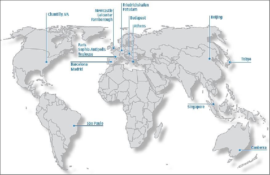
Geo-Information Services of Astrium
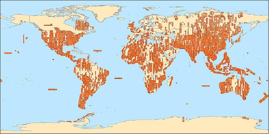
• December 2012: With more than 50 direct receiving stations operating on all five continents, Airbus Defence and Space has the most extensive station network in the world today. Imagery is downlinked instantly from the optical and radar satellites operated by Airbus Defence and Space each time they pass over these stations, making it possible to deliver fresh information from any area of interest very quickly. New SPOT-6, SPOT-7 and Pléiades receiving stations are set to further shorten image data delivery times, getting data into the hands of users faster than ever before (Ref. 58).
• Spot Image and Infoterra joined forces within Astrium Geo-Information Services to offer a consolidated product and services portfolio under the Astrium brand. The merger took place in May 2010. On January 1, 2011, a single operational management structure was implemented. 67)
A single operational management structure started on January 1, 2011, bringing closer together the satellite imagery and geoinformation specialists Spot Image and Infoterra to form the GEO-Information division of Astrium Services. As a global, integrated company, the GEO-Information division of Astrium Services is implementing this new organization with a single vision in mind: to better respond to the needs of customers.
The GEO-Information Services division will offer:
• a one-stop shop for data from the SPOT and TerraSAR-X satellites, and from Pleiades
• a single product and services portfolio covering the entire geographic information value chain from satellite imagery to value-added services and turnkey solutions.
ERMEX receiving station: In the spring of 2012, Astrium Services signed an agreement with the government of Mexico to upgrade the ERMEX receiving station south of Mexico City. This station will enter service in September 2012. Equipped with a high-tech antenna and a new-generation SPOT terminal, it will initially receive SPOT-5 imagery and then SPOT-6 imagery when commercial operations get underway. It also received data from SPOT-7 in 2014. 68)
References
1) P. B. de Selding, "Spot Image's Next Satellite to be Built Mainly with Private Capital," Space News, Jan. 21, 2008, Vol. 19, Issue 3, p. 1
2) Philippe Campenon, "Pleiades and SPOT-6: Earth observation in high and very high resolution," Proceedings of the 60th IAC (International Astronautical Congress), Daejeon, Korea, Oct. 12-16, 2009, IAC-09-B1.2.6
3) Marc Mangolini, Didier Giacobbo, "LTDP Policy and Implications of a European LTDP System Spot-1/5 –Spot-6 Pleiades Formosat-2 –Kompsat-2," Long Term Data Preservation Workshop, ESA/ESRIN, Italy, May 27-28, 2008, URL: http://earth.esa.int/gscb/ltdp/presentations/20.ltdp_approach_spot_image.pdf
4) "Re-inventing the Constellation," SPOT magazine #48, 1st semester 2010, URL: https://web.archive.org/web/20190715013716/www.infoterra.es/asset/cms/file/sm48_pleiades-eng.pdf
5) Peter B. de Selding, "Spot Commits to New Satellites, But Funding Questions Remain," Space News, June 15, 2009, pp. 1 +13
6) Peter B. de Selding, "Astrium Services Cleared to Buy New Spot Satellites, Space News, June 22, 2009, p. 13
7) Igor Lampin, Didier Giacobbo, "FORMOSAT-2, KOMPSAT-2, ASTROTERRA," GSCB (Ground Segment Coordination Body) Workshop, June 18-19, 2009, ESA/ESRIN Frascati, Italy, URL: http://earth.esa.int/gscb/papers/4.8_Lampin.pdf
8) Peter B. de Selding, "Spot Image Not Counting on French Government Support," Space News, March 22, 2010, URL: http://www.spacenews.com/civil/100322-spot-image-not-counting-french-government-support.html
9) Information provided by Pascal Michel, Astrium Services, Toulouse, France. Pascal Michel is in charge of Web Communication in Astrium GEO-Information Services (fomer Spot Image)
10) Eric Maliet, Michel Siguier, Gérard Carrin, Ange Defendini, Didier Radola, "Applying satellite product lines to affordable Earth observation systems," Proceedings of the 4S (Small Satellites Systems and Services) Symposium, Portoroz, Slovenia, June 4-8, 2012
11) "Airbus Group Takes Off Into 2014 With Joint Brand," Airbus Group, January 2, 2014, URL: http://www.airbus-group.com/airbusgroup/int/en/news/press.20140102_airbusgroup_new_brand.html
12) "Enhancing Competitiveness – EADS Outlines Plan for Defence and Space Restructuring," EADS, Dec. 9, 2013, URL: http://www.eads.com/eads/int/en/news/press.20131209_eads_enhancing_competitiveness.html
13) GSCB (Ground Segment Coordination Body Workshop) Presentation SPOT /AstroTerra, June 6-7, 2012, Frascati, Italy, URL: http://earth.esa.int/gscb/papers/2012/16b-ASTRIUM_SPOT-AstoTerra.pdf
14) Dominique. Pawlak, Thomas Schirmann, "The New Generation of Astrium Earth Observation Optical Systems," Proceedings of the Symposium on Small Satellite Systems and Services (4S), Funchal, Madeira, Portugal, May 31-June 4, 2010
15) "SPOT 6 and SPOT 7: extending SPOT continuity to high-resolution, wide-swath imagery," Astrium Geo-Information Services, URL: http://www.astrium-geo.com/en/147-spot-6-7
16) "SPOT 6 / SPOT 7 Technical Sheet," Astrium, URL: http://www.astrium-geo.com/files/pmedia/edited/r18072_9_spot_6_technical_sheet.pdf
17) Eric Maliet, "SPOT 6 and SPOT 7 : offering SPOT data continuity," Proceedings of the 64th International Astronautical Congress (IAC 2013), Beijing, China, Sept. 23-27, 2013, paper: IAC-13-B1.4.10
18) https://web.archive.org/web/20100714224623/http://www.astrium.eads.net/en/equipment/coreci-an-integrated-compression-recording-and-ciphering-solution-for-earth.html
19) Michael Stähle, Tim Pike, "ADCSS 2012 Astrium - Current and Future Mass Memory Products," Proceedings of ADCSS (Avionics Data, Control and Software Systems) Workshop, ESA/ESTEC, Noordwijk, The Netherlands, Oct.23-25, 2012, URL:
http://congrexprojects.com/docs/12c25_2510/09stahele_astriumfinal.pdf?sfvrsn=2
20) "PSLV-21 - 100th Indian Space Mission," ISRO brochure, Sept. 4, 2012, URL: https://web.archive.org/web/20141023082647/www.isro.org/pslv-c21/pdf/pslv-c21-brochure.pdf
21) "SPOT 6 joins Pléiades 1A in orbit," EADS Astrium, Sept. 9, 2012, URL: https://web.archive.org/web/20130403020153/http://www.astrium.eads.net/en/press_centre/spot-6-joins-pleiades-1a-in-orbit.html
22) "PSLV to Launch French Remote Sensing Satellite - SPOT - 6," IRSO Press Release, April 3, 2012, URL: http://www.isro.gov.in/pressrelease/scripts/pressreleasein.aspx?Apr03_2012
23) "Launch of SPOT 7 completes Airbus Defence and Space observation satellite constellation," Airbus Defence and Space, June 30, 2014, URL: http://www.space-airbusds.com/en/press_centre/launch-of-spot-7-completes-airbus-defence-and-space-observation-satellite.html
24) Patrick Blau, "India's PSLV Rocket successfully delivers SPOT-7 & Small Satellites to Orbit," Spaceflight 101, June 30, 2014, URL: http://www.spaceflight101.com/pslv-c23---spot7-launch-updates.html
25) "PSLV-C23 brochure," ISRO, URL: https://web.archive.org/web/20141006155824/www.isro.org/pslv-c23/pdf/pslv-c23-brochure.pdf
26) "AISat satellite transmits from space," DLR, June 30, 2014, URL: http://www.dlr.de/dlr/en/desktopdefault.aspx/tabid-10081/151_read-10812/year-all/#/gallery/15477
27) "Airbus to provide near real-time access to its satellite data," Airbus Press Release, 30 Jan. 2018: URL: http://www.airbus.com/content/dam/corporate-topics/publications/press-release/Press%20Release%20CIS%2030012018%20ENG.pdf
28) "SPOT 6/7 Farming Just Got Better with Improved Satshot Mapping Imagery and Airbus," Satnews Daily, Aug. 28, 2017, URL: http://www.satnews.com/story.php?number=613604642
29) "SPOT 6/7 imagery for improved efficiency of US agriculture," GeoConnexion, Aug. 28, 2017, URL: http://www.geoconnexion.com/news/spot-6-7-imagery-for-improved-efficiency-of-us-agriculture/
30) "Airbus and Scanex to feed Russia's most popular search engine Yandex with "One Atlas" satellite imagery data," Airbus DS, May 24, 2017, URL: https://airbusdefenceandspace.com/newsroom/news-and-features/airbus-and-scanex-to-feed-russias-most-popular-search-engine-yandex-with-one-atlas-satellite-imagery-data/
31) Information provided by David Golden, 3D Optical and SPOT Product Manager, Communications, Intelligence & Security, Airbus Defence and Space, Toulouse, France.
32) Information provided by Eldaniz Aliyev, and Fidan Behbudova of Azercosmos OJSC (Open Joint Stock Company), Baku, Azerbaijan.
33) "New Processing Options for Pléiades and SPOT 6/7 Products," Airbus DS, Feb. 2017, URL: http://www.intelligence-airbusds.com/en/7717-new-processing-options-for-pleiades-and-spot-67-products
34) http://www.intelligence-airbusds.com/en/5750-image-gallery-search-results?world=2254
35) "SPOT 6/7 eyes the Kiribati Republic," Sept. 2016, eoPortal, URL: https://www.intelligence-airbusds.com/en/5751-image-gallery-details?img=38259#.Y3Ntz3bMKUk
36) "Ngambè Tikar, Cameroon," Airbus DS, image of the week, Feb. 2016, URL: https://www.intelligence-airbusds.com/en/5751-image-gallery-details?img=38259#.Y3Ntz3bMKUk
37) "SPOT 6/7 Complete Coverage Over South Africa in Just 3 Months," Airbus DS, Aug.18, 2015, URL: https://web.archive.org/web/20160320152456/http://www.geo-airbusds.com/en/6754-spot-67-complete-coverage-over-south-africa-in-just-3-months
38) "Airbus Defence and Space NEWTON products enable agile satellite missions," Airbus DS, April 15, 2015, URL: http://www.space-airbusds.com/en/press_centre/airbus-defence-and-space-
newton-products-enable-agile-satellite-missions.html
39) "SPOT and Pleiades data available for research and application development," ESA, April 10, 2015, URL: https://web.archive.org/web/20210509113625/https://earth.esa.int/web/guest/missions/3rd-party-missions/current-missions/spot/news/-/article/spot-and-pleiades-data-available-for-research-and-application-development
40) "Third Party Mission - Welcome to the SPOT Information Area," ESA, URL: http://tinyurl.com/qa8ztqp
41) https://earth.esa.int/web/guest/missions/3rd-party-missions/current-missions/spot
42) "Airbus Defence and Space announces the Commercial Launch of SPOT 7 satellite," Airbus DS Press Release, Dec. 2, 2014: http://www.satcom-airbusds.com/wp-content/uploads/2014/12/cis-76-2014-n-02122014-eng.pdf
43) Peter B. de Selding, "Airbus Sells In-orbit Spot 7 Imaging Satellite to Azerbaijan," Space News, Dec. 4, 2014, URL: http://spacenews.com/42840airbus-sells-in-orbit-spot-7-imaging-satellite-to-azerbaijan/
44) "Azercosmos OJC to operate SPOT 7 high resolution optical Earth observation satellite," Dec. 2, 2014, URL: http://en.trend.az/azerbaijan/society/2339323.html
45) "Azercosmos" OJC to operate and commercialize SPOT-7 high resolution optical Earth observation satellite, to be renamed as Azersky," Dec. 2, 2014, URL: http://azercosmos.az/azercosmos-ojc-to-operate-and-commercialize-spot-7-high-resolution-optical-earth-observation-satellite-to-be-renamed-as-azersky
46) "SPOT-7 In-Orbit Testing Runs Smoothly," Airbus Defence and Space, URL: [web source no longer available]
47) "First images from SPOT 7 satellite within three days after launch," Airbus Defence and Space, July 4, 2014, URL: http://www.astrium-geo.com/en/5928-first-images-from-spot-7-satellite-within-three-days-after-launch
48) K. S. Jayaraman, "India's PSLV Rocket Lofts Airbus Spot 7 Satellite," SpaceNews, June 30, 2014, URL:
http://www.spacenews.com/article/launch-report/41070india%E2%80%99s-pslv-
rocket-lofts-airbus-spot-7-satellite
49) "Fully qualified Flash Memory optimizes Satellite Data Storage," Airbus Defence and Space, May 19, 2014, URL: [web source no longer available]
50) Information provided by Jérôme Soubirane, SPOT Product Manager, Geo-Intelligence, Airbus Defence and Space, Toulouse, France.
51) Ajit Sampath, Dong Han Lee, "A look at Pleiades 1-B and SPOT data," Proceedings of JACIE 2014 (Joint Agency Commercial Imagery Evaluation) Workshop, Louisville, Kentucky, USA, March 26-28, 2014, URL: https://calval.cr.usgs.gov/wordpress/wp-content/uploads/14.003_Sampath_Pleiades_SPOT_JACIE20141.pdf
52) Brian Cutler, "Pléiades 1B and SPOT 6 Image Quality status after commissioning and 1st year in orbit," Proceedings of JACIE 2014 (Joint Agency Commercial Imagery Evaluation) Workshop, Louisville, Kentucky, USA, March 26-28, 2014, URL: https://calval.cr.usgs.gov/wordpress/wp-content/uploads/14.025_Cutler_JACIE2014-Airbus-Constellation-PHR1BSPOT6.pdf
53) "SPOT-6 1.5m Ortho Pan-sharpened (12 bits) sample imagery," URL: http://www.astrium-geo.com/en/23-sample-imagery
54) "Astrium's satellites qualified by the European Union within the framework of CAP," Astrium, July 18, 2013, URL: [web source no longer available]
55) Drew Hopwood, "Pleiades-1A and -1B, SPOT-6 & -7 — Status of Astrium GEO-Information Services' EO Satellite Constellation," 12th Annual JACIE (Joint Agency Commercial Imagery Evaluation) Workshop, St. Louis, MO, USA, April 16-18, 2013, URL:
https://calval.cr.usgs.gov/wordpress/wp-content/uploads/Astrium-Constellation-Status.pdf
56) "SPOT 6 Completes Technical Commissioning," Astrium Services, January 2013, URL: http://www.astrium-geo.com/na/4589-spot-6-completes-technical-commissioning
57) "SPOT 6 & 7 - Turkey Steps up Collaboration with Astrium Services," Astrium Services, Dec. 20, 2012, URL: http://www.astrium-geo.com/en/4582-spot-6-7-turkey-steps-up-collaboration-with-astrium-services
58) "Positioning Status Report," Astrium, URL: http://www.astrium-geo.com/na/4515-spot-6-success-story-2
59) Astrium Services, Sept. 12, 2012, URL: http://www.astrium-geo.com/en/19-gallery?img=12518&search=gallery&type=0&sensor=0&resolution=0&continent=0&application=0&theme=0
60) "First Images from SPOT 6," Astrium Services, Sept. 13, 2012, URL: http://www.astrium-geo.com/na/4423-first-images-from-spot-6
61) P. Luquet, A. Chikouche, A. B Benbouzid, J. J Arnoux, E. Chinal, C Massol, P. Rouchit(1), S. de Zotti, "NAOMI instrument: a product line of compact & versatile cameras designed for high resolution missions in Earth observation," Proceedings of the 7th ICSO (International Conference on Space Optics) 2008, Toulouse, France, Oct. 14-17, 2008
62) Information provided by Michel Pascal of Astrium Services, Toulouse, France
63) Jean-Michel Dussauze, Alain Gevert, Jacques Troillard, "AstroTerra Control Ground Segment: Cost reduction through automation and product line," Proceedings of the SpaceOps 2010 Conference, Huntsville, ALA, USA, April 25-30, 2010, paper: AIAA 2010-1916
64) Jean-Michel Dussauze, Gérard Feltrin, Jacques Troillard, "AstroTerra Control Ground Segment: Operations concept and implementation," Proceedings of SpaceOps 2012, The 12th International Conference on Space Operations, Stockholm, Sweden, June 11-15, 2012
65) "ADS unveils multi-satellite Direct Receiving Station for GeoNorth," Space Daily, June 26, 2014, URL:
http://www.spacedaily.com/reports/ADS_unveils_multi_satellite_Direct_
Receiving_Station_for_GeoNorth_999.html
66) "Airbus Defence and Space supplies KSAT with Norway's first TerraSAR-X Direct Receiving Station," Airbus Group, June 26, 2014, URL: http://www.airbus-group.com/airbusgroup/germany/
de/presse/press.20140626_airbus_defence_and_space_ksat.html
67) "Astrium fully integrates Spot Image and Infoterra into new GEO-Information business division," Dec. 1, 2010, URL: https://web.archive.org/web/20130403004609/http://www.astrium.eads.net/en/press_centre/astrium-fully-integrates-spot-image-and-infoterra-into-new-geo-information.html
68) "Astrium Installs New Terminal in Mexico to Receive SPOT 6 and 7 Imagery," Astrium, Sept. 4, 2012, URL: http://www.astrium-geo.com/na/4364-astrium-installs-new-spot-terminal-in-mexico
69) De Selding, Peter B., “https://www.spaceintelreport.com/azerbaijan-acknowledges-azersky-spot-7-loss-appears-to-have-selected-israels-iai-for-2-satellite-120m-successor/'”, Space Intel Report, April 28, 2023, URL: https://www.spaceintelreport.com/azerbaijan-acknowledges-azersky-spot-7-loss-appears-to-have-selected-israels-iai-for-2-satellite-120m-successor/