SPOT-4
EO
Ocean
Multi-purpose imagery (ocean)
Ocean imagery and water leaving spectral radiance
Learn about SPOT-4, the French Earth-imaging satellite launched in 1998 for global crop monitoring and environmental studies. Mission ended in 2013.
Quick facts
Overview
| Mission type | EO |
| Agency | CNES |
| Mission status | Mission complete |
| Launch date | 24 Mar 1998 |
| End of life date | 29 Jun 2013 |
| Measurement domain | Ocean, Land |
| Measurement category | Multi-purpose imagery (ocean), Multi-purpose imagery (land), Vegetation, Albedo and reflectance, Landscape topography |
| Measurement detailed | Ocean imagery and water leaving spectral radiance, Land surface imagery, Vegetation type, Fire fractional cover, Earth surface albedo, Leaf Area Index (LAI), Land cover, Land surface topography, Normalized Differential Vegetation Index (NDVI), Photosynthetically Active Radiation (PAR), Fraction of Absorbed PAR (FAPAR) |
| Instruments | Vegetation, DORIS (SPOT), HRVIR |
| Instrument type | Imaging multi-spectral radiometers (vis/IR), High resolution optical imagers, Precision orbit |
| CEOS EO Handbook | See SPOT-4 summary |
Related Resources
Summary
Mission Capabilities
SPOT-4 has various instruments that consist of two High-Resolution Visible and Infrared Sensors (HRVIR) and one Vegetation Monitoring Instrument (VMI). The two High-Resolution Visible and Infrared Sensors (HRVIR) collect data via five spectral bands:
- one panchromatic band,
- three multispectral bands
- one shortwave infrared band (SWIR).
The HRVIR instrument, along with Vegetation Monitoring Instrument (VMI) produce multi-purpose imagery of both the land and the ocean, specifically data concerning albedo and reflectance, vegetation, and landscape topography. SPOT-4 also has an additional sensor called the Doppler Orbitography and Radio-positioning Integrated Satellite (DORIS) which provides orbital data that determines where the constellation is relative to the Earth.
The SPOT-4 spacecraft also includes the payload systems PASTEC (Un Passager Technologique de SPOT-4) and POAM-II (Polar Ozone and Aerosol Measurement II). The PASTEC system involves a multitude of technologies that study the orbital environment, studying concepts such as the measurement of satellite dynamics (MEDY) and electrostatic potentials outside the SPOT spacecraft (SILLAGE). POAM-II provides a measurement of the vertical distribution of atmospheric ozone, nitrogen dioxide, aerosol extinction, water vapour and temperature.
Performance Specifications
The High-Resolution Visible and Infrared Sensor (HRVIR) is a pushbroom imager that contains a telescope with a focal length of 1.08m and an aperture of f/3.5. The HRVIR has a field of view equating to 4.13° which corresponds to 60km of ground coverage. The strip-selection mirror enables adjustments of viewing direction of ± 27°, controlled by a stepper-motor that adjusts in increments of 0.3°. The bands of the HRVIR differ in resolution: the panchromatic band has a resolution of 10m, with the three multispectral bands as well as the shortwave infrared band having a resolution of 20m each.
The Vegetation Monitoring Instrument (VMI) has a ground swath width of 2200km and a resolution close to 1km. The total field of view is 101° with a pixel size of 1.15km at nadir. The VMI attains a spatial coverage of about 90% of the equatorial regions that are imaged each day, with instruments collecting radiation reflected from the Earth’s surface. Three spectral vegetation bands (B2, B3, SWIR) and three HRVIR bands (Red, NIR, SWIR) are identical but distinct to other bands, allowing data to be collected at high and low resolutions.
Space and Hardware Components
SPOT-4 has upgrades in its design and engineering principles as compared to its predecessor model SPOT-3. The refinements are evidenced in the lifespan of the spacecraft (from a 3-year lifespan to a 5-year lifespan), the satellite bus (SPOT MK2) and a larger service module that accommodates twice the payload of the SPOT-3 bus. There is also increased storage capacity from 22 minutes to 44 minutes that corresponds to 240 gigabit with a new 10 gigabit solid-state memory added to increase onboard recording capabilities.
SPOT-4
SPOT-4 is considered a 2nd generation SPOT-series satellite of CNES, France. The most important advance is the addition of the “Vegetation” instrument, with four spectral bands to allow continuous, worldwide crop monitoring. The data may be used for crop forecasts and environmental studies.
Spacecraft
The SPOT-4 S/C design differs from the earlier SPOT series (SPOT-1,2,3) in the following aspects: five years design lifetime instead of three; a new extended platform design, the SPOT-4 satellite bus referred to as SPOT MK2, [provided by MMS (Matra Marconi Space), Toulouse] and service module are employed accommodating twice the payload of the former SPOT 3 bus). The propulsion module consists of a frame made of aluminium bars and two capillary tanks holding 158 kg of hydrazine.
The S/C is 3-axis stabilized. Attitude is sensed by an inertial platform consisting of four rate gyros, two digital Earth sensors, and two digital sun sensors. The actuators employed are three magnetic-bearing reaction wheels, two magnetic torquers (to control the speed of the reaction wheels), and two types of hydrazine thrusters each producing a force of 3.5 N or 15 N. SPOT-4 offers increased onboard storage capacity (from 22 minutes to 40 minutes, corresponding to 240 Gbit), the pointing accuracy is <0.15º (3σ). In addition, a 10 Gbit solid-state memory was added to increase the overall onboard recording capability.
S/C mass = 2755 kg (2550 kg dry mass). The solar array is articulated using SADM (Solar Array Drive Mechanism), providing an average power of 2.2 kW. The solar array consists of 5 panels (size of 25 m2) covered with solar cells (8640 silicon cells). The NiCd battery consists of 4 units each with a capacity of 40 Ah. 1) 2) 3) 4)
Launch
The SPOT-4 spacecraft was launched on March 24, 1998, on an Ariane-4 vehicle from Kourou.
Orbit: Sun-synchronous circular orbit, altitude = 832 km, inclination = 98.8º, repeat cycle of 26 days, period = 101.5 min, descending node at 10:30 AM (equatorial crossing time).
RF communications:
An experimental spread-spectrum transceiver, ESBT (Experimental S-Band Terminal), built by Alcatel Espace under ESA contract. ESBT is being used for S-band TT&C transmissions to/from the ground segment. The ESBT is also being used to test the intersatellite link between SPOT-4 (in LEO) and ARTEMIS in GEO. ESBT is a DSP-based satellite Earth station modem capable of handling data bit rates from 128 to 32768 bit/s in steps of 1 bit/s. The spreading code chip rate is 3 Mchip/s. The ESBT instrument package consists of: 5)
- Transponder proper transmitting telemetry and receiving commands on a 2 GHz carrier at 4 kbit/s
- Tracking antenna offering hemispherical coverage, mounted on the satellite's anti-earthward panel, for optimal link efficiency
- Command and control interface controlling ESBT operations.
The ESBT is independent of the host satellite's mission, its only direct contact with the SPOT system being through the SPOT-4 operations control centre. ESBT is being used operationally to relay SPOT 4 housekeeping telemetry via ARTEMIS to the SPOT-4 control centre. This capability will significantly enhance the SPOT-4's housekeeping telemetry coverage. Whereas each station in the CNES TT&C network provides just 10 to 15 minutes of contact time per pass, the ESBT will offer 30 to 40 minutes of continuous contact as a result of the considerably longer periods of contact between SPOT-4 and ARTEMIS (and considerably longer periods of contact between SPOT 4 and Artemis). This will be a major step forward, particularly when monitoring onboard operations that must be watched closely and continuously (e.g. during recovery operations after a period in safe mode).
The spread-spectrum technique involves mixing a useful digital signal (here at 4 kbit/s) with a complex pseudo-random code (in this case at 3 Mbit/s).
In addition, an X-band telemetry subassembly provides downlink transmission of stored image data. Also, an L-band telemetry subassembly is installed to send image data directly to ground stations.
Mission Status
• The end-of-life of the SPOT-4 mission was on June 29th, 2013. 6)
• SPOT-4 reached its new orbit on Jan. 29, 2013. CNES started the TAKE5 mission 2 days later, until June 19, 2013 — after a mission extension for the Sentinel-2 project of ESA. During this period, a time series of SPOT-4 images were acquired every 5 days using 42 sites scattered over nearly all continents. Several space and research agencies (ESA, NASA, CCRS, JRC) also contributed to the mission by funding the cost for the edition of products acquired on sites they selected among the 42. 7)
The TAKE5 mission was run from Feb 1 to June 19, 2013, during which period almost 1700 images were acquired. Only 25 images were lost during the whole mission due to X-band station failure.
The ground segment was implemented simultaneously with data acquisition. During the TAKE5 mission, the MUSCATE processing chain was modified and tuned to produce:
- level 1C products (data orthorectified reflectance at the top of the atmosphere)
- level 2A products (data orthorectified surface reflectance after atmospheric correction, along with clouds mask and their shadow, and mask of water and snow).
Most of the images acquired had been processed at levels 1C and 2A, except some of them were affected by an unusual image localization error which didn’t allow performing correct image ortho-rectification and integration in image series for image superposition.
The first TAKE5 data set, the first production of THEIA (French Land Data Center), was released on July 15, 2013. This data set has been reprocessed in August to take into account additional TAKE5 data, not yet received for the first processing, and correction of processing bugs. The last release includes the update of absolute calibration coefficients (Ref. 7).
• CNES was planning for June 2013 to begin the long process of de-orbiting SPOT-4 for reentry into Earth’s atmosphere at some point within the next 25 years. This is in compliance with the recommendations of the IADC (Inter-Agency Space Debris Coordination Committee).
- However, already in January 2013, SPOT- 4 was given a new lease of life as a key element of the “Take5” mission from early February to June 19, 2013. The aim of this mission, managed by CNES, is to pave the way for the future Sentinel-2 mission. The ESA family of Sentinel satellites is set to replace the Envisat satellite and meet requirements for the Copernicus services. 8)
CESBIO took the opportunity to set up the Take-5 experiment at the end of SPOT-4's commercial life: this experiment will use SPOT-4 as a simulator to give the project a hint of the time series that ESA’s Sentinel-2 mission will provide. 9)
After 6 months of feasibility studies, CNES decided to launch the Take5 experiment. - On January 29, 2013, the SPOT-4 orbit reached its new lowered orbit by 3 km to obtain a 5-day repeat cycle orbit. SPOT-4 will follow this orbit until the end of May 2013. During this period, 42 sites will be observed every 5 days, as in the case of Sentinel-2. The data will be processed and distributed by the PTSC (Pôle Thématique Surfaces Continentales) and distributed to users by the end of June 2013.
• On January 11, 2013, the commercial operations of the SPOT-4 satellite were terminated. The joint decision on stopping commercial operations of the satellite was made by the SPOT-4 owner - CNES (French Space Agency) and the satellite Operator - Astrium GEO-Information Services. 10)
- The satellite has been operating for almost 15 years (177 months) since its launch in March 1998. Over 6.8 million images of the Earth have been acquired since then.
• The SPOT-4 mission end is foreseen for the end of 2012. 11)
• The SPOT-4 spacecraft and its payload are operating nominally in 2012. There were no changes during the past year. The solid-state memory unit is still unusable after the switch performed on the redundant chain in the TMCU case (2009; both magnetic onboard recording units (EMS) are still operational, so SPOT-4 keeps its nominal recording capability unchanged). 12)
• On June 25, 2011, SPOT-4 captured a new volcano eruption in Chile (Figure 7). A new crater began erupting on June 4, 2011, in the Puyehue-Cordón Caulle volcano range in the Andes, near the Chile-Argentina border. The eruption sent a huge plume of ash 10 km high and 5 km wide into the air which threatened the health of residents in the surrounding area. Over 4,000 people have been evacuated. The SPOT-4 image was tasked for the International Charter on Space and Major Disasters to support evacuation and mitigation planning. 13)
The new crater is 4.5 km from Puyehue, a cone stratovolcano that peaks at 2,236 meters. Eruptions of this volcano range can be very explosive, as it sits atop the Peru-Chile Trench where the Nazca Plate is sliding under the South American Plate at a rate of 7 cm a year.
• The SPOT-4 spacecraft and its payload are “operating nominally” in 2011. The life expectancy for SPOT-4 remains unchanged at the end of 2012. 14)
- The PASTEC end of service could be decided by end of 2011, due to the end of data exploitation of ERCOS and SILLAGE experiences. Indeed, the ERCOS data is received erratically since October 12, 2010, and the actions to try to recover ERCOS data permanent delivery have been ended on 15th of November 2010. The data is no longer exploited by experts since the end of January 2011 due to the unreliability of data delivery rate/frequency. SILLAGE data are no more exploited either by experts due to no more need.
- In 2010, SPOT-4 lost the solid state memory (MdM) use capability, linked with the switch performed on the redundant chain in the TMCU. Nevertheless, both magnetic onboard recorders (EMS) are still operational so SPOT-4 keeps its nominal recording capability unchanged, the MdM being a probationary experience for solid-state recorders on board (Ref. 14).
• In June 2010, Spot Image announced that its satellite data archive has reached 100 billion km2 (1011 km2) of Earth’s land surfaces. Since 1986, the SPOT satellites have been building up this archive of colour and black-and-white imagery every day, offering resolutions of 2.5 - 20 m. 15)
• Infoterra France SAS, a subsidiary of Astrium, has merged with Spot Image SA effective 3 May 2010. - Closer integration between these two well-matched entities has been underway since 2008 when Astrium acquired the shareholding in Spot Image owned by the French space agency CNES (Ref. 15).
• The SPOT-4 spacecraft and its payload are “operating nominally” in 2010 (> 12 years of serv16)ice provision). Operational analysis studies conducted by CNES project a life expectancy to the end of 2012 for the SPOT-4 mission. 17)
• In 2009/10, an anomaly occurred on the EAIM (Electronic supply of Inertial and Magnetic Actuators) subsystem involving the wheels command of satellite attitude control. The switch to the redundant system has fixed the problem.
• Due to the natural ageing of the on-board equipment, the operations team switched in January 2010 the TMCU (Thermal control modelling of the SPOT payload telemetry) to the redundant chain (QPSK-B / ATOP-B) to prevent an increase of the current and power levels. This re-established full functionality on TMCU.
• Orbital drift of SPOT-4: The project decided to tolerate some natural orbital drift due to dwindling fuel resources of the spacecraft (some fuel must be kept in reserve for deorbiting manoeuvres). However, this meant that SPOT-4 was getting closer to SPOT-5 in relative time. To avoid potential conflicts in the data acquisition of the ground stations, the orbital altitude of SPOT-4 was increased slightly (for a certain period) to reverse the drift situation. In January 2010, SPOT-4 was again manoeuvred to the correct nominal altitude - after having achieved a separation of 138º between SPOT-4 and SPOT-5, corresponding to almost 40 minutes in relative time; only 2.8 kg of hydrazine were being used (Ref. 17). In Feb. 2010, the separation achieved between SPOT-4 and SPOT-5 was 166º.
• On January 9, 2008, some communications problems did arise with the SPOT-4 passenger instrument PASTEL (communications link to ARTEMIS). The problem area involved recurrent protocol anomalies between the instrument-specified flying software and the central flying software. The problem was being attended to - but it could not be fixed. Hence, at some time in 2008, the PASTEL operations were simply retired since all repair initiatives did fail.
In all, PASTEL provided slightly less than 5 years of service for free-space communication transmissions between ARTEMIS and SPOT-4. There were a total of 2018 laser communication links requested and 1862 were effectively done (156 cancelled communications). A total of 1789 transmissions were properly conducted, bringing to 96.08% of the success rate. The duration of all transmissions was around 378 hours for all communication sessions.
• As of May 1, 2006, the POAM-III passenger instrument operation became inactive due to an instrument failure (freeze of the optical head).
• PASTEC: Only ERCOS and SILLAGE are operational as of 2007. The other subsystems of PASTEC became inactive according to their life expectancy.
• Since April 1, 2003, ARTEMIS has been routinely providing high-data-rate links to SPOT-4 of CNES and to Envisat of ESA. Both the optical and Ka-band links are providing very-high-quality image transmission. SPOT-4 has been using one link session per day to transmit its data via ARTEMIS to CNES in Toulouse.
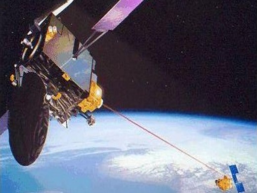
• In Nov. 2001, ARTEMIS made a world premiere by establishing a laser link with the French Earth Observation satellite SPOT-4: imaging data was sent by SPOT-4 using a laser beam as a signal carrier to Artemis and from there by radio waves to the ground. At the time, ARTEMIS was still in a parking orbit (the geostationary orbit was reached in January 2003 by means of electric propulsion). 20) 21)
The scene covers an area of approximately 60 km x 60 km, from the southern limits of the city of Orange (right at the top) to the shores of the delta and the town of Saintes-Mairies de la Mer (right at the bottom). The Rhone river crosses the picture from north to south.
Sensor Complement
Improvements: introduction of electronic sensor gains matching according to landscape type and season, thus ensuring greater dynamic range. In addition, the imaging instruments are no longer susceptible to glare or affected by the polarization of the incident light.
HRVIR (High-Resolution Visible and Infrared Sensor)
HRVIR consists of 2 pushbroom imaging units, an improved version of HRV. Spectral ranges: B1=0.50 - 0.59 µm, B2=0.61 - 068 µm, B3=0.79 - 0.89 µm, SWIR= 1.58 - 1.75 µm (a supplementary band in the 20 m multispectral mode at 1.58-1.75 µm is provided). The panchromatic band (0.51 - 0.73 µm of HRV on SPOT-1,-2,-3) has been replaced by band B2, enabling the 10 and 20-meter resolution data to be co-registered onboard the satellite instead of on the ground. Same pointing geometries and resolution capabilities as HRV. In addition, the two HRVIR sensors can be programmed for independent image acquisition (viewing directions of both sensors are independent). Both HRVIR instruments are protected against polarization or blinding by direct sunlight.
The SWIR detector (1.58 - 1.75 µm) uses new-generation InGaAs/InP linear arrays. The 3000 detectors required to achieve a ground resolution of 20 m are aligned in a plane by assembling ten ”bricks” end to end, each brick comprising 300 CCD detectors.
The main elements of HRVIR are:
the telescope, the detection unit, the image processing electronics, and the viewing direction control mechanism. The telescope (catadioptric Schmidt telescope type) has a focal length of 1.08 m and an aperture of 3.5. The incoming beam is split into four spectral channels by a beam-splitter consisting of prisms and filters, then focused onto four rows of linear CCD detectors [one line of 6000 (PAN) and three lines of 3000 (MS) pixels, the four rows of detectors simultaneously generate four lines of “registered” pixels]. The SWIR band uses InGaAs/InP linear arrays developed specifically for the purpose. FOV = 4.13º corresponding to 60 km of ground coverage. 22)
Band name | Spectral range | Spatial resolution |
B1 | 0.50 - 0.59 µm | 20 m |
B2 | 0.61 - 0.68 µm | 20 m |
B3 | 0.79 - 0.89 µm | 20 m |
Pan | 0.61 - 0.68 µm | 10 m |
SWIR | 1.58 - 1.75 µm | 20 m |
Oblique viewing capability:
The entrance to each HRVIR features a strip-selection mirror enabling the viewing direction to be adjusted through ± 27º about nadir. Adjustment is controlled by a stepper motor moving through increments of 0.3º. For each position, the viewing direction is accurate to within 200 m on the ground.
The oblique viewing technique is used in three ways:
• to acquire imagery, in response to programming requests, anywhere within an observable corridor extending 450 km to either side of the satellite ground track, corresponding to oblique viewing between the extreme angles of ± 27º
• to acquire any given scene from two viewing angles to yield a stereo-pair for stereo restitution and relief mapping
• to move to a position enabling the instrument to look at a calibration source.
HRVIR calibration:
The calibration system allows image signals to be corrected in two ways: (used at regular intervals to check and, if necessary, adjust the instrument response).
• In-band calibration (also referred to as CCD detector response normalization), the aim is to balance the response of the 3000 detectors in each band while the instrument views a perfectly uniform landscape
• Absolute calibration to measure the instrument's dynamic responsivity by establishing a precise relationship between a perfectly stable external source (the sun) and the instrument's output signal.
Vegetation
An additional sensor for SPOT-4, called Vegetation or VMI (Vegetation Monitoring Instrument), with a ground swath width of 2200 km, and a resolution close to 1 km [European project with the cooperation of the EC, France (CNES), Sweden (SNSB), Belgium (OSTC) and Italy (ASI), designed by Aerospatiale as the prime contractor and built by SODERN of Limeil-Brivannes], providing the capability of wide-area monitoring of the Earth's vegetation (VMI features advanced optics that allow perfect geometrical rectification of the pictures despite the wide swath width. The VMI optics virtually cancel the curvature of the Earth to provide directly usable geographical information). Calibration accuracy: interband and multitemporal =3%, absolute = 5%; TFOV = 101º (swath width of about 2200 km); pixel size = 1.15 km at nadir; location accuracy < 0.5 km, local distortion <0.3 pixels, collocation with HRVIR sensor data = 0.3 km for simultaneous acquisitions. Spatial coverage: about 90% of the equatorial regions are imaged each day (total daily imaging for latitudes >35º).
The instrument collects radiation reflected by the earth's surface. Silicon linear detector arrays are used for spectral band B0 (blue), B2 (red) and B3 (near infrared), while InGaAs photodiodes (Thomson CSF) are used for the SWIR (Short Wave Infrared) band. Each array features 1728 individual CCD detectors. The output voltage signals are fed to a multiplexer (prior to this, SWIR voltages are adjusted for dark current values), then to a single analogue-to-digital converter(ADC). All sensors are processed by a single high-precision 11-bit ADC, thus completely bypassing the problem of electronic interband calibration.
The Vegetation package is an independent add-on payload to the SPOT satellite [the package includes the sensor, a solid-state recorder (up to 97 minutes of imagery), an X- and L-band telemetry subsystem, and a computer]. The instrument design uses four cameras, one for each spectral band, each camera is covering the TFOV. Vegetation payload parameters: mass = 152 kg, power = 200 W, instrument size = 0.7 m x 1 m x 1 m, data transmit frequencies in X-band (8153 MHz) at 3.4 Mbit/s, and L-band (1704 MHz), the data rate of the sensor (L-band) = 510 kbit/s. 23)
Three spectral bands of Vegetation (B2, B3 and SWIR) and HRVIR (Red, NIR, SWIR) are identical, they register perfectly allowing data to be interpreted at several scales. The combination of high and low spatial resolutions (of HRVIR and Vegetation) provides a major contribution to the measurement of temporal changes over a few points or at certain time periods for a proper determination of the influence of the various kinds of ground cover. 24)
The Vegetation processing center (CTIV) is at VITO (Vlaamse instelling voor technologisch onderzoek - Flemish institute for technological research), located in Mol, Belgium. The commercial distribution of Vegetation products is provided on a global scale by SPOT Image (France), with CLEO (Belgium), SSC Satellitbild (Sweden) and Telespazio (Italy).
Channel | Spectral Range | Surface Reflection Range (albedo) | Radiometric Resolution NEΔR | Optimized to detect |
B0 (Blue) | 0.43 - 0.47 µm | 0.0 - 0.5 | 0.003 | chlorophyll |
B2 (Red) | 0.61 - 0.68 µm | 0.0 - 0.5 | 0.001 albedo ≤0.1 | vegetation |
B3 (NIR) | 0.78 - 0.89 µm | 0.0 - 0.7 | 0.003 | vegetation, atmospheric correction |
SWIR | 1.58 - 1.75 µm | 0.0 - 0.7 | 0.003 | vegetation, atmospheric correction |
DORIS (Doppler Orbitography and Radiopositioning Integrated by Satellite)
DORIS is a satellite-based orbit determination and radiopositioning system, designed and developed by CNES, GRGS (Groupe de Recherches de Géodésie Spatiale), CNRS/Université Paul Sabatier) and IGN (Institut Géographique National). The SPOT-4 DORIS package includes experimental software (DORIS/DIODE experiment) to provide the POD (Precise Orbit Determination) function in real-time to within <0.3 m on the radial component. 25)
DORIS is an RF system using a dual-frequency Doppler (400 MHz and 2 GHz) uplink to measure the velocity of a satellite in orbit relative to a global, permanent network of 51 so-called ”orbitography ” beacons. At the same time, the system can be used to locate beacons on the ground. Two ”master ” beacons serve as time and frequency references for the system and also handle uploading of the commands and data needed by the onboard receiver.
The instrument consists of a receiver (MVR- range rate measuring device), a USO (Ultrastable Oscillator) and an omnidirectional antenna, all carried on the host satellite. The receiver takes Doppler shift measurements of 400 MHz and 2 GHz radio signals transmitted by the beacons. The 400 MHz measurement is being used to correct errors caused by ionospheric signal propagation.
SILEX (Semiconductor Intersatellite Link Experiment)
SILEX is an ESA experiment built by MMS. SILEX consists of two optical terminals, namely PASTEL on board SPOT-4 (a LEO terminal) on the anti-Earth side of the SPOT platform, and OPALE, mounted on ESA's geostationary satellite ARTEMIS (a GEO terminal). ARTEMIS was launched on July 12, 2001, and established the first laser link with SPOT-4 in Nov. 2001. The ARTEMIS downlink to the ground segment link uses conventional radio transmission (Ka-band). The SILEX payload on SPOT-4 (namely PASTEL) has a mass of 157 kg, power = 150 W. 26) 27)
• PASTEL (PAssager SPOT de Técommunication Laser).
A joint ESA/CNES passenger demonstration experiment. PASTEL is a prototype high data-rate intersatellite transmission system based on laser technology. The objective is to transmit imaging data from SPOT-4 to ARTEMIS. The aim of the experiment is to validate the PASTEL concept design in an operational environment. PASTEL is a gimbal-mounted assembly consisting of a telescope, an optical bench with a fine pointing system, communication detectors with avalanche photodiodes, a thermal control system for precision temperature control, a two-axis gimbal mechanism, and the launch locking mechanisms needed during the launch phase. The telescope mirrors and main structural elements are made of Zerodur. The acquisition and tracking sensors use CCD detectors. The laser diodes are of the GaAlAs type. The SPOT-4 - ARTEMIS optical links operate at wavelengths of 830 nm. Data to be transmitted include HRVIR image data, pseudo-noise (PN) code, PASTEL telemetry.
• OPALE (Optical Payload for Intersatellite Link Experiment) terminal, mounted on the geostationary satellite ARTEMIS (a GEO terminal).
Laser links have the potential to offer much higher transmission rates (up to 10 Gbit/s) than conventional radio links which are limited to rates of about 250 Mbit/s. Another advantage of laser links is that by their very nature, there can be no interference between optical and radio transmissions. The technical challenge of the technology demonstration involves alignment and stabilizing issues, it requires pointing errors of < 10 µrad. This pointing accuracy is several orders of magnitude lower (i.e., better) than the open-loop pointing of a typical platform.
The divergence tolerance of the communication beam for the SILEX configuration is 8 μrad (or about 0.00046º). PASTEL and OPALE use a dedicated acquisition sequence. Initially, both terminals (PASTEL and OPALE) coarsely point to each other. This is done when OPALE scans a wide-angle (750 μrad) beacon beam in the direction of PASTEL. On illumination of PASTEL by the beacon beam, it rapidly corrects its line of sight and directs in turn a narrow communication beam towards OPALE. Similarly, OPALE detects the incoming PASTEL signal, aligns its line of sight, and transmits its narrow communication beam towards PASTEL. The two terminals then remain locked on each other in closed-loop tracking, permitting subsequent communication.
PASTEC (un PASsager TEChnologique de SPOT 4)
PASTEC is a technology demonstration passenger payload to study the orbital environment. PASTEC contains the following experiment packages (PASTEC package mass = 50 kg, power = 50 W): 28)
• CEDRE: Contamination and degradation of thermal control coatings in space. The objective is to study the variation with time of the thermo-optical properties of thermal control coatings using a calorimetric method combined with contamination measurement using quartz-crystal microbalances.
• ERCOS: Cosmic radiation experiment. The objective is to study the effects of heavy ion fluxes on VLSI electronic components.
• ERDOS: Radiation dosimetry experiment. The aim is to measure cumulative radiation doses with MOS dosimeters.
• MEDY: Measurement of satellite dynamics. The objective is to characterize the vibration environment during the launch phase
• MicroMEDY: The objective is the characterization of the in-flight microvibration environment.
• SILLAGE: Measurement of electrostatic potentials on the outside of the SPOT satellite which are due to the “wake” effect. The objective is to evaluate the behaviour of the materials used and to gain insights into the electrostatic discharge hazard comparable with our current understanding of the corresponding phenomena affecting geostationary spacecraft.
• THERME: same goals as CEDRE, but highly simplified. The aim is to study the ageing of thermal control coatings depending on their exposure to solar and terrestrial radiation and on their orientation with respect to the satellite's velocity vector (exposure to and effects of atomic oxygen) using a calorimetric method based on simplified sensors.
POAM-III (Polar Ozone and Aerosol Measurement)
POAM-III is an NRL instrument (now sponsored by ONR instead of BMDO as done before), an improved version of POAM-II flown on SPOT-3. The objective is the measurement of the vertical distribution of atmospheric ozone, water vapour, nitrogen dioxide, aerosol extinction, and temperature. Improvements were made in the electronic system that provides lower noise and more accurate measurements.
POAM-III is a nine-channel photometer device with a lightweight and low-power design. The instrument mounts on the exterior of SPOT-4 have a size of 22 cm x 23 cm x 34 cm, and a mass of 13.9 kg. A PCEM (Primary Control and Electronics Module) with a mass of 11 kg is mounted inside the S/C. The optical head assembly of the outside instrument includes an azimuth-elevation gimbal mount to track the sun. The azimuth and elevation axes move the line-of-sight parallel and perpendicular to the Earth's horizon. The range of elevation is from -10º to -35º, and the range of azimuth motion is ±173º from a nominal zero position.
The measurement technique is by solar occultation through the Earth's atmospheric limb at nine wavelengths from the UV to NIR. There are separate filtered optics for each of the nine channels, which are co-aligned with each other and the sun tracker. The new optical filters have a greater ability to withstand the space environment. The wavelengths and bandwidths of the science channels differ slightly from those in POAM-II and are given in Table 3. 29) 30)
Channel | Primary Measurement | Center Wavelength (nm) | Bandwidth at FWHM (nm) |
1 | Rayleigh scattering | 353.4 | 9.7 |
2 | NO2 present | 439.6 | 2.1 |
3 | NO2 absent | 442.2 | 2.1 |
4 | O3 | 603 | 17.7 |
5 | O2 present | 761.3 | 2.3 |
6 | O2 absent, aerosol | 779 | 10.2 |
7 | H2O absent, aerosol | 922.4 | 2.6 |
8 | H2O present | 935.9 | 2.6 |
9 | Aerosol | 1018 | 11.6 |
Each of the nine wave bands is measured by a separate optical channel. An image of the sun is formed with a fused silica plano-convex lens having a clear aperture of 11 mm, a nominal focal length of 63 mm, and an f-number of f/5.7. The detectors are silicon photodiodes operated in photovoltaic mode (data quantization of 15 bits). The instrument tracks the sun as it rises and sets through the atmosphere, using a four-cell sun tracker with a 1º FOV. For POAM-III, the 1º sensor is supplemented with a 10º sensor to accommodate initial acquisition.
POAM-III measurement extent in altitude ranges: Aerosols = 10-30 km; O2, O3 = 10-60 km; H2O = 10-40 km; NO2 = 20-40 km.
References
1) F. Achard, J. P. Malingreau, T. Phulpin, G. Saint, B. Saugier, B. Segun, D. Vidal-Madjar, “The Vegetation Instrument on Board SPOT-4 - A Mission for Global Monitoring of the Continental Biosphere,” LERTS brochure, Toulouse, 1990
2) http://spot4.cnes.fr/spot4_gb/index.htm
4) http://spot4.cnes.fr/spot4_gb/nouveau.htm#Les%20nouveaut%C3%A9s%20du%20satellite%20SPOT%204
5) http://spot4.cnes.fr/spot4_gb/esbt.htm
6) Information provided by Alain Lapeyre of CNES, Chef de Service Exploitation des Satellites de Télédétection.
7) Laurence Houpert, Frédéric Daniaud, Olivier Hagolle, Sylvia Sylvander, Jordane Sarda, Sylvain Ramos, Grégory Beaumet, R. Broca, Michel Moulin, Lionel Vintenat, Jean-Marc Walter, François Rimbert, Michael Wheeler, Jean-Pascal Chognard, Steeve Maitrel, Jérôme Bijac, Jean-Louis Raynaud, J. Recoules, L. Bray, “Take five experiment : using end of SPOT-4 satellite operational life for simulating the future Sentinel-2 mission,” Proceedings of the 64th International Astronautical Congress (IAC 2013), Beijing, China, Sept. 23-27, 2013, paper: IAC-13-B6.2.10
8) “SPOT 4 undertakes new mission before being de-orbited,” Astrium Services, 2013, URL: http://www.astrium-geo.com/en/4612-spot-4-undertakes-new-mission-before-being-de-orbited
9) “A new French Data Center dedicated to Land Surfaces,” CESBIO, Jan. 9, 2013, URL: http://www.cesbio.ups-tlse.fr/multitemp/?tag=products
10) “End of commercial operations of SPOT 4 satellite,” ScanEx RDC, Jan. 15, 2013, URL: http://press.scanex.ru/index.php?option=com_k2&view=item&id=3724:spot4&lang=en
11) J. N. Hourcastagnou, P. Cales, “GSCB Workshop Presentation SPOT / AstroTerra,” 3rd GSCB (Ground Segment Coordination Body) Workshop, 2012, ESA/ESRIN, Frascati, Italy, June 6-7, 2012, URL: http://earth.esa.int/gscb/papers/2012/16b-ASTRIUM_SPOT-AstoTerra.pdf
12) Information provided by Laurence Houpert of CNES (for the SPOT mission team), Toulouse, France
13) “New Volcano Eruption in Chile,” Astrium, 2011, URL: http://www.astrium-geo.com/en/153-new-volcano-eruption-in-chile
14) Information provided by Laurence Houpert of CNES, Toulouse, France
15) “Archive hits 100 billion sq.km,” SPOT magazine No 48, 1st semester 2010
16) “SPOT 4 opened the 2010 imaging season,” URL: http://mycoordinates.org/spot-4-opened-the-2010-imaging-season/
17) Information provided by Frédéric Tavera, SPOT Mission Exploitation Manager of CNES, Toulouse, France
18) “Operational monitoring of wildfires,” SPOT magazine No 49, 2nd semester 2010
19) http://www.csrsr.ncu.edu.tw/.../Update%20SPOT%204.pdf
20) “A world first: data transmission between European satellites using laser light,” Nov. 21, 2001, URL: http://eu.spaceref.com/news/viewpr.html?pid=6668
21) “Perfect images transmitted via a laser link between Artemis and SPOT 4,” Dec. 6, 2001, URL: http://www.esa.int/esaCP/ESAI8MZ84UC_index_0.html
22) http://spot4.cnes.fr/spot4_gb/hrvir.htm
23) Information provided by T. Genet of CNES, Toulouse
24) R. H. Frazer, Z. Li, R. Landry, “SPOT Vegetation for characterizing boreal forest fires,” International Journal of Remote Sensing, Vol. 21, No 18, 2000, pp. 3525-3532
25) G. Taverniera, H. Fagard, M. Feissel-Vernier, F. Lemoine, C. Noll, J. Ries, L. Soudarin, P. Willis, “The International DORIS Service,” Advances in Space Research, Vol. 36, Issue 3, 2005, pp. 333-341
26) T. Tolker-Nielsen, J. C. Guillen, “SILEX: The First European Optical Communication Terminal in Orbit,” ESA Bulletin 96, Nov. 1998, pp. 42-44
27) A. F. Popescu, B. Furch, “Status of the European developments for laser intersatellite communications,” SPIE, Vol. 1866, 1993, pp. 10-20
28) “PASTEC: Technology demonstration passenger,” URL: http://spot4.cnes.fr/spot4_gb/pastec.htm
29) “Polar Ozone and Aerosol Measurement (POAM III),” URL: http://www.iapmw.unibe.ch/research/projects/issi/workshop1/presentations/Nedoluha%20POAM2.pdf
30) R. L. Lucke, D. R. Korwan, et. al., “The Polar Ozone and Aerosol Measurement (POAM-III) instrument and early validation results,” Journal of Geophysical Research, Vol. 104, D15, Aug. 20, 1999, pp. 18,785 - 18,799
The information compiled and edited in this article was provided by Herbert J. Kramer from his documentation of: ”Observation of the Earth and Its Environment: Survey of Missions and Sensors” (Springer Verlag) as well as many other sources after the publication of the 4th edition in 2002. - Comments and corrections to this article are always welcome for further updates.(eoportal@symbios.space)