SpinSat (Special Purpose Inexpensive Satellite)
Non-EO
US (NRL)
Quick facts
Overview
| Mission type | Non-EO |
| Agency | US (NRL) |
| Launch date | 21 Sep 2014 |
| End of life date | 11 Mar 2017 |
SpinSat (Special Purpose Inexpensive Satellite)
Spacecraft Launch Sensor Complement Cyclops Deployer Mission Status References
SpinSat is a small satellite mission of NRL (Naval Research Laboratory), Washington D.C. in partnership with DSSP (Digital Solid State Propulsion) LLC of Reno, NV, to demonstrate and characterize the on-orbit performance of ESP (Electrically -controlled Solid Propellant) technology in space. This is an enabling technology for the small satellite community that will allow small satellites to perform maneuvers. 1) 2) 3)
NRL is designing the spacecraft, and DSSP is designing the electrically controlled solid propulsion system. The SpinSat spacecraft is based on the experience of two ANDE (Atmospheric Neutral Density Experiment) missions of NRL:
1) ANDE was launched as ANDERR (ANDE Risk Reduction) on Shuttle flight STS-116 on Dec. 10, 2006.
2) ANDE-2 was launched on Shuttle flight STS-127 on July15, 2009.
SpinSat will provide a test platform to demonstrate and characterize the on-orbit performance of the thruster technology.
There are two primary goals of the SpinSat mission. The first goal is to characterize the performance of the ESP thrusters on orbit. The second goal of the mission is to provide a calibrated drag experiment at higher solar activity than the ANDERR and ANDE-2 missions to provide a monitor of total neutral atmospheric density.
Spacecraft
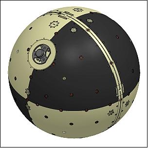
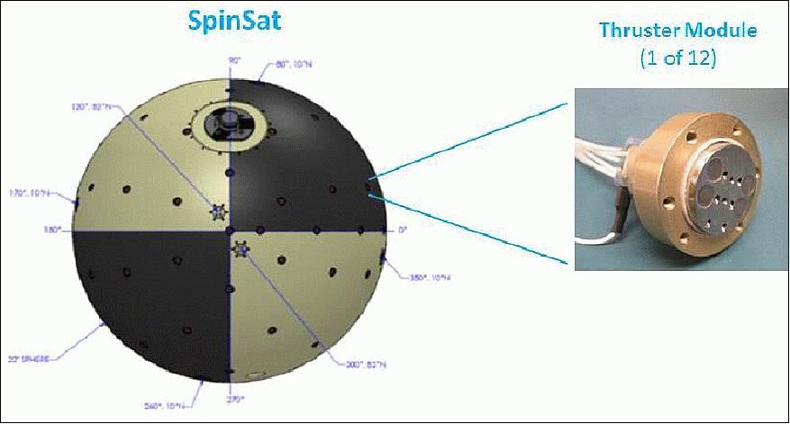
The SpinSat spacecraft is an aluminum sphere of 558 mm in diameter and a mass of 57 kg (Figure 1) with the ESP thrusters physically arranged on the exterior of the satellite to provide two basic maneuvers as spin-up (de-spin) maneuver and a normal thrust maneuver. For the spin-up maneuver, pairs of thrusters will be co-aligned 180º apart, will provide a tangential component force on the exterior; for de-spin, a 2nd pair of thrusters will provide the opposite force. For the normal thrust maneuver, the thrusters will be oriented perpendicular to the exterior of the satellite to provide force in the normal direction. Another set of thrusters placed at the opposite pole will provide normal force in the opposite direction.
The spacecraft itself acts as the primary sensor for the third experiment; with a well-determined and characterized ballistic coefficient, the routine collection of radar tracking and satellite laser ranging data will provide a high-resolution atmospheric drag data set used to derive thermospheric density.
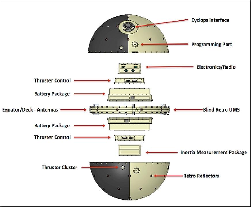
Spacecraft design: An exploded view of SpinSat is shown in Figure 2. The thrusters are located in four pairs to induce a spin (de-spin) of the spacecraft along latitudinal bands located at ±15º. Two pairs of thrusters are aligned normal to the sphere surface located in latitudinal bands at ±82º.
SpinSat is fitted with a set of sixty-eight 12.7 mm diameter optical retroreflectors for SLR (Satellite Laser Ranging) located along five latitudinal bands at ±90º, ±67.5º, ±45º, ±22.5º, and 0º with one, six, eight, ten, and ten retroreflectors/ band, respectively. The last eight retroreflectors are located along a longitudinal band of 0° with latitudes of ±11.25º, ±33.75º, ±56.25º, and ±78.75º.
An interface bracket to the Cyclops deployment system is located at 45° latitude and 90° longitude. This bracket provides the sole interface to the Cyclops clamp mechanism, it acts as a push-off plane for the Cyclops separation springs, and houses the four separation switches (ITW series 65 model 401000 over travel switch) that inhibit SpinSat from powering up until it is deployed from the Cyclops. These switches/springs comprise a non-coplanar, parallel force system whose moments are balanced to minimize dip off during deployment.
Four Nitinol antennas of 0.3 mm in diameter are stowed in a shallow groove along the equator of SpinSat. Each antenna is 190 mm long from the tip to the surface of SpinSat and is loped and crimped at the free end. Three independent nylon ties that are severed by a burn wire after the SpinSat is deployed from Cyclops, restrain each antenna.
The fabrication of the hemispheres was accomplished by using a technique known as centrifugal casting. This process was chosen over three other possible ways of fabrication, which were as follows: metal spinning, investment/sand casting, and machining. The decision to use centrifugal casting was based on previous proven performance and cost.
Electrical Design of SpinSat
The electrical design consists of a stack of circuit boards. Starting at the bottom, the first board is the timer board. This board incorporates the NASA safety required timer circuits that operate independently and delay the powering of the satellite bus. The three independent timers receive power through the arm plug which connects two four separation switches which connect to the batteries. When the timers are activated, they will count for specified period and trigger latching relays. The latching relays turn the timers off and turn power on to the satellite bus.
EPS (Electric Power Subsystem). The EPS board includes a 5 V regulator for the DHU (Data Handling Unit), power switches for antenna release, power converters for the thrusters, and a discrete watchdog time that will cycle power to the satellite bus if not reset in time.
DHU (Data Handling Unit): The DHU board is using an ATMEGA1280 microcontroller. It was chosen for its low power operation, multiple serial interfaces, and existing flight software from previous satellites. The DHU includes a micro-SD card for data storage, a real time clock to support scheduled operations, and interface circuitry to interface to the thruster controllers and sensors.
RF communications: The communications board consists of a transmitter and receiver. The transmitter is the Stensat Radio beacon to be operated at 9.6 kbit/s. It will output2 W of RF signal into a dipole antenna through a balun. The receiver is a Stensat transceiver design using only the receiver section since the frequency coordination will put the uplink at about 450 MHz and downlink at about 401 MHz. The transceiver cannot switch between the two frequencies due to the range of the VCO (Voltage-Controlled Oscillator).
Four antennas are installed around the equator of the satellite at equal distances. They are paired at opposite sides to make two dipoles, one for transmit and one for receive. The antenna material is made of nitinol, a flexible metal alloy that can maintain a straight shape and can be stowed with tight bends. The antennas will be stowed in a trough along the equator and secured with a nylon cord. A resistor will be used to cut the cord by heating up and melting the cord. This has been done on previous satellites with great success.
Thruster Design
The SpinSat propulsion system is based on DSSP's first-generation microthruster design. A microthruster consists of two coaxial electrodes separated by ~1 mm of ESP (Electric Solid Propellant). ESP represents a new thruster technology that employs a special new class of energetic but non-pyrotechnic materials known as Electrically-controlled Solid Propellants (ESPs). ESPs have the unique property that they are ignited only by the application of electric current. Unlike conventional rocket motor propellants that are difficult to control and extinguish, ESPs can be ignited reliably at precise intervals and durations. Moreover, the technology is attractive because it requires no moving parts and the propellant is insensitive to flames or electrical sparks. The objective of the ESP experiment is to fly an array of electrically-controlled solid propellant thrusters for initial space flight demonstration on SpinSat.
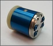
T he center electrode is a stainless steel rod and the outer electrode is a hollow aluminum case. The total length is 13 mm, which amounts to 0.1 gram of propellant (Ref. 1).The ESP based thrusters are unique in that they can be turned on and off, at will using only electrical power with no moving parts. Figure 3 illustrates the construction and operation of ESP coaxial microthrusters. 4) 5)
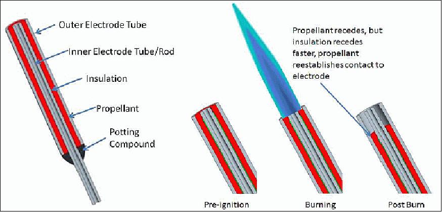
The key feature of the microthruster is that the center electrode is wrapped with an insulating plastic over the majority of its length. The plastic stops near the thruster opening, leaving a small conductive path on the face of the thruster. When current sufficient for ignition is applied, the plastic will burn along with propellant, creating a subsequent layer of conductive ESP. This patented "burn-away" method is designed to ensure even and flat propellant ignition from the face of the thruster down to its base.
UMS (Universal Mounting System) thruster cluster: For the SpinSat mission, DSSP's microthrusters were adapted to the satellite's existing UMS plugs. This simplified the satellite structural design and allowed for a modular propulsion solution. On SpinSat, each UMS plug houses six microthrusters. There are twelve of these UMS "clusters" or 72 total thrusters per satellite. The UMS clusters are identical with the exception of a flow straightener plate, which guides the propellant exhaust gases at an angle relative to the normal direction. Angled plates are installed on UMS clusters that are tasked with rotational maneuvers. Straight plates are added to the UMS clusters tasked with translational maneuvers. Of the 12 UMS clusters installed on the satellite, 8 are accommodated angled and 4 are straight.
Figure 4 shows a cross-section of a UMS cluster and illustrates the key design features. Rather than having separate outer cases, each thruster case is formed by machining a single piece of aluminum. Thus, the aluminum is an electrode common to all thrusters. The six center electrodes protrude from the rear of the UMS, where they mate directly with the cable harness.
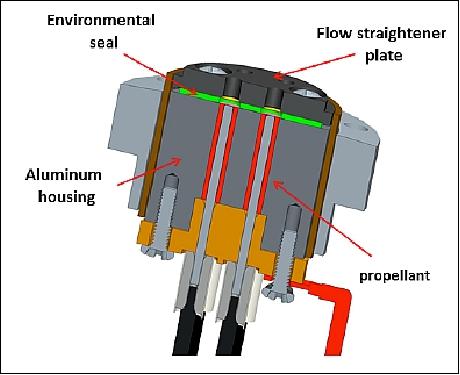
To protect the propellant from contaminants, the UMS is designed with an environmental barrier that sits between the flow straightener plate and the electrodes. Multiple layers of Mylar, Teflon, and Viton serve this purpose (Figure 5).
Thruster Electronics Design
Ignition power control: ESP ignites when sufficient power density is achieved in the propellant. However, designing a power delivery system is challenging because the propellant conductivity is highly variable. It varies with the applied electric field, temperature, pressure, ignition history, and several other parameters. A particularly interesting characteristic is that ESP conductivity increases rapidly in the presence of strong electric fields. In fact, for small electrode gaps such as that of the microthruster, the load will appear as a short circuit at critical voltage levels. Consequently, the propulsion controller must not only regulate power to the load, but also tolerate intermittent short-circuit conditions.
DSSP's solution is a switching power converter that operates in current-mode. Specifically, the circuit is a non-inverting buck-boost converter that has very little output filter capacitance. Current, delivered from a DC source, is stored in an inductor and then released into the load. The switch timing is such that all of the inductor current, and thus the energy, is allowed to dissipate in the load before the next charge cycle begins. In this way, since frequency and inductor current are programmable, average power is controlled. Typical values for energy and frequency on the SpinSat are 0.002 Joule and 100 kHz, respectively, which amounts to 200 W of ignition power, including losses. Since the current is limited on a per-cycle basis, intermittent short-circuits are tolerated.
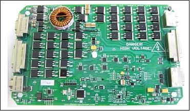
PCM (Propulsion Control Module): The power converter is the heart of the PCM (Propulsion Control Module). The PCM is a single-sided PCB Printed Circuit Board) assembly that contains the converter power electronics, the microcontroller and logic devices, communications hardware, and an array of MOSFET switches that perform individual thruster addressing, shown in Figure 6. Two PCMs exist on the SpinSat – each is tasked with controlling 6 UMS clusters or 36 thruster elements.
The power supply for the PCM is a regulated 5 VDC, a 0.2 A bus is provided by the avionics system. Since this is not enough power to drive the thrusters directly, immediate thruster power comes from a bank of capacitors. The PCM uses four wet tantalum capacitors, wired in series and charged to 190 V. The caps are housed in the PCM enclosure, but are installed separately in a rigid plastic dish. It takes approximately three minutes to charge the capacitors prior to each ignition pulse.
Each PCM has a dedicated RS-422 serial communications interface with the avionics host. The host configures the PCM prior to issuing a fire command. Configuration commands include thruster selection (any subset of 36 thrusters can be addressed), power level setting, and pulse width setting (adjustable over 50, 100, and 200 ms). Each PCM interfaces with its UMS clusters using a cable harnesses.
Thruster Testing
DSSP has tested their millipound-scale microthrusters on a thrust stand and verified that their performance is adequate to perform the mission of positioning SpinSat in all directions. This performance has been verified both with bare thrusters in vacuum as well as with integrated, flight-weight and flight-design UMS sets of 6 microthrusters; it has also been verified after being subjected to the critical tests outlined in the NASA GSFC-STD-7000 standards for environmental verification. Due to its survival of launch-equivalent vibration, humidity soak, thermal vacuum, and the ability to fire at high and low temperatures more stringent than those seen on a prior equivalent spherical satellite mission, and due to the thrusters' ability to still provide useful thrust after those tests, DSSP's electric solid propellant-using thrusters have passed environmental qualification and are ready for launch and on-orbit operation.
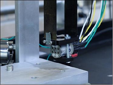
Testing hardware: All performance testing has been conducted at DSSP inside a vacuum chamber pumped to a vacuum pressure ≤ 0.1 millitorr to simulate near-Earth environments. All thrusters were placed on DSSP's microthruster thrust stand, capable of measuring impulse bits between 0.00001 and 0.01 pound-seconds with ±10% accuracy (±5% from 0.0001 to 0.001 pound-seconds, where most thruster performance resides). Figure 6 shows the thrust stand with a test article mounted; the thrust stand behaves as a pendulum, with a laser finding the magnitude over time of the pendulum's deflection when subjected to a force. The resulting decaying exponential can be reduced to a force vs. time curve with high accuracy.
Thruster performance results: Testing proceeded in multiple stages. In the first stage, baseline performance data was gathered with thrusters under no environmental stressors save vacuum, which represented the best-case of performance. In the second stage, a variety of tests (vibration, thermal cycling, vacuum soak, etc.) were performed individually and the thrusters fired to measure each separate test's effect on performance. The final phase, full qualification, saw every test done to the thrusters collectively, and then thrusters fired to measure final expected-on-orbit performance.
Launch
SpinSat of the DoD Space Test Program (STP) was launched on Sept. 21, 2014 (05:52:03 UTC) as a secondary payload and part of the soft-stow cargo allotment on the SpaceX Dragon spacecraft (Falcon-9v1.1 launch vehicle) of the SpX-4 (SpaceX CRS-4) resupply mission to the ISS.
Orbit: ISS near-circular orbit with an altitude of ~400 km and an inclination of 51.6º.
CRS-4 Payloads
Dragon delivers ~2270 kg of supplies and payloads, including critical materials to support 255 science and research investigations that will occur during Expeditions 41 and 42. Dragon carries three powered cargo payloads in its pressurized section and two in its unpressurized trunk. — Dragon will return with about 1725 kg of cargo, which includes crew supplies, hardware and computer resources, science experiments, space station hardware, and four powered payloads (recovery in the Pacific Ocean ~ 700 km off the coast of California). 6)
• RapidScat is the primary payload on this CRS-4 flight of SpaceX.
• 3D Print device of Made in Space Inc. of Mountain View, CA.
• New permanent life science research facility. The Bone Densitometer (BD) payload, developed by Techshot, will provide a bone density scanning capability on ISS for utilization by NASA and CASIS (Center for the Advancement of Science in Space). The system measures bone mineral density (and lean and fat tissue) in mice using DEXA (Dual-Energy X-ray Absorptiometry).
For the first time, Dragon will carry live mammals – 20 rodents will ride up in in NASA's Rodent Research Facility, developed by scientists and engineers at NASA's Ames Research Center. The rodent research system enables researchers to study the long-term effects of microgravity—or weightlessness—on mammalian physiology.
Secondary payloads:
• Arkyd-3 is a 3U CubeSat technology demonstrator (4 kg) from the private company Planetary Resources Inc. of Bellevue, WA, USA, (formerly known as Arkyd Astronautics). The objective is to test the technology used on the future larger Arkyd-100 space telescope. The company has contracted with NanoRacks to take the Arkyd-3 nanosatellite to the ISS where it will be released from the airlock in the Kibo module. 7)
• SpinSat, a microsatellite (57 kg) of NRL (Naval Research Laboratory), Washington D.C.
• SSIKLOPS (Space Station Integrated Kinetic Launcher for Orbital Payload Systems). This launcher will provide still another means to release other small satellites from the ISS. This system is also known by its nickname Cyclops and is described in the SpinSat file on the eoPortal. 8)
Sensor Complement
The SpinSat payload consists of two inertial sensors, ADIS16385, chosen for their accelerometer sensitivity. The ADIS16130 was chosen for measuring rotational motion about the z-axis. The ADIS16385 will be used to measure the acceleration generated by the normal mounted thrusters while the ADIS16130 will measure the rotational rate changes from the tangential thrusters. Since the sensors have digital interfaces, the interface circuitry is simple and handled by a custom microcontroller board using Arduino software.
On-orbit operations: Once deployed SpinSat will power up a few minutes after the plunger inhibit switches disengage from the Cyclops pusher plate. The spacecraft will go through early orbit checkout to verify command and control capabilities, reference instrumentation functionality, and thruster control module performance verification. The characterization of the ESP (Electrically-controlled Solid Propellant) thruster technology will be performed by firing the ESP thrusters in pairs and measuring the changes to the spin rate via on-board rate instrumentation. Ground campaigns by the ILRN (International Laser Ranging Network) will also provide a high resolution means to determine the spin rate of SpinSat from the ground. Small ΔV firings normal to the surface of SpinSat will be characterized by the on-board accelerometers. The lifetime of the satellite is expected to be >6 months and characterization should be complete within the first four months.
Cyclops Deployer System
NASA/JSC (Johnson Space Center) in collaboration with the STP (Space Test Program) of DoD developed a dedicated 50-100 kg class ISS microsatellite deployment system named Cyclops. The system will utilize NASA's ISS resupply vehicles to launch microsatellites to the ISS in a controlled pressurized environment in soft stow bags. The satellites will then be processed through the ISS pressurized environment by the astronaut crew allowing satellite system diagnostics prior to orbit insertion. Orbit insertion is achieved through use of JAXA's (Japan Aerospace Exploration Agency) Experiment Module Robotic Airlock (JEM Airlock), and one of the ISS Robotic Arms. 9) 10)
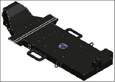
The general Cyclops layout is shown in Figure 9. Cyclops interfaces with the JEM Airlock (AL) Slide Table, the ISS Robotic Arms, and the deployable satellites. It is being designed to be able to be utilized for the duration of the ISS mission for the deployment of microsatellites. The platform has a size of ~ 127 cm L x 61 cm W x 7.6 cm H, capable of deploying satellites of any geometry up to 100 kg, contingent upon the satellites meeting all Cyclops and ISS safety requirements. These requirements are under development and will be available from the ISS Program when completed.
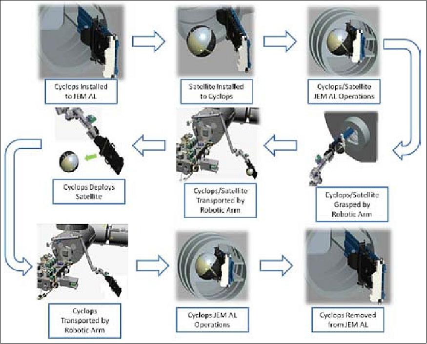
Concept of operations: Cyclops, will be launched onboard one of NASA's ISS resupply vehicles in a controlled pressurized, soft stowed environment. It will then be removed from its launch configuration by the astronaut crew and placed in its stowed location until needed.
Once a satellite deployment has been scheduled, Cyclops will be removed from its on-orbit stowage bag and placed on the JEM Airlock Slide Table. The deployable satellite will be placed on Cyclops. Cyclops and its attached satellite will be processed through the JEM Airlock to the ISS external environment. Upon completion of JEM Airlock operations Cyclops and its attached satellite will be grasped by either the ISS robotic arm, or the JEM robotic arm, and transported to its predetermined deployment position.
Cyclops will then deploy the satellite away from the ISS. After successful deployment of the satellite Cyclops will be maneuvered back to the JEM Airlock and secured on the JEM Airlock Slide Table. JEM Airlock operations will be conducted bringing Cyclops back inside the ISS, where it will be removed from the JEM Airlock Slide Table and placed in its on-orbit stowage bag. This concept of operations is illustrated in Figure 10.
Demonstration mission: Cyclops' initial satellite deployment demonstration will consist of two microsatellites:
1) SpinSat of NRL within the DoD/STP program
2) LONESTAR-2 (Low earth Orbiting Navigation Experiment for Spacecraft Testing Autonomous Rendezvous and docking) of TAMU (Texas A&M University) located in College Station, TX, and UTA (University of Texas at Austin). LONESTAR-2 has a mass os 56 kg and a size of 66 cm x 76 cm x 30.5 cm.
Both microsatellites are manifested on the SpX-4 (SpaceX CRS-4) resupply mission to the ISS in Q2 12014. The LONESTAR program of NASA/JSC consists of a series of four missions in which two satellites will ultimately demonstrate autonomous rendezvous and docking capabilities. Each mission consists of a pair of satellites, one each built by TAMU and UTA, demonstrating key technologies for development toward the final mission.
The current mission, LONESTAR-2, consists of AggieSat4 with partner satellite Bevo-2 contained inside. The two satellites will be launched and deployed together from the ISS via the Cyclops. After deployment from the ISS, AggieSat4 will release Bevo-2 and conduct on-orbit operations, including taking photographs of one another, as well as other mission events, operating the on-board GPS, called Dragon, developed by NASA/JSC, stabilization and pointing control, and crosslink communicating between the satellites, sharing data for calculating relative navigation solutions.
The two satellites, SpinSat and LONESTAR-2, will be launched as pressurized cargo in the SpaceX Dragon vehicle, but could also be launched as pressurized cargo in the ATV, HTV, or the Cygnus modules. Contained within foam padded soft stow cargo bags, the spacecraft only needs to meet the less stringent launch loads of soft-stow items. Multiple launch opportunities are available based on the readiness date of the satellites and the resupply vehicle manifest. To prepare for deployment, the crew removes the spacecraft from its stowage bag and attaches it to the Cyclops. The crew verifies the inhibit states and performs other actions such as removing handling fixtures, attaching antennas, or verifying the health of the spacecraft. After deployment, the spacecraft's transmitters will be inhibited on-board until it reaches a safe distance from the ISS. Deployment is expected to occur at approximately 400 km in the retrograde direction.
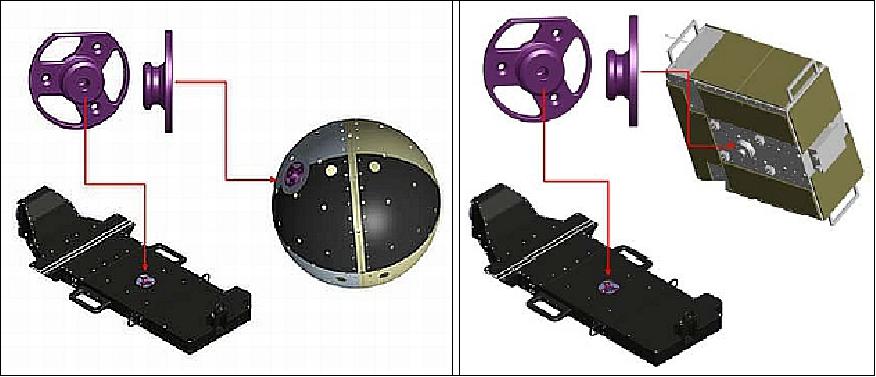
Microsatellite interface requirements: The interface between Cyclops and the satellite is shown in Figure 11. It attaches to the microsatellite via 3 bolts. It has a mass of approximately 0.11 kg.

The fixture attaches to the bottom of the satellite and interfaces with the Cyclops grapple system as shown in Figures 12. It remains with the satellite at deployment.
Requirement | Description |
Ballistic Number (BN) | Satellite shall have a ballistic number of ≤100 kg/m2. BN=mass / (frontal area x Cd) where Cd=2.0 |
Center of Gravity (CG) | Satellite shall meet the defined Cyclops' defined CG corridor (TBD). |
Deployment Force | The satellite shall be able to withstand the maximum force (TBD) applied from Cyclops at the deployment interface during deployment. |
Electrical Bonding | The satellite shall provide a Class S electrical bonding path to Cyclops |
Impact | The satellite shall meet the ISS robotic arm potential transfer impact loads without creating debris. |
Inhibit Switch Contact Surfaces | The satellite shall maintain keep out zones with its inhibit switch locations and contact surfaces. |
Mass | Satellite shall meet the mass of ≤100 kg (includes the mass of the experiment attachment fixture). |
Safety | The satellite shall meet all ISS Payload Safety requirements. |
Structural/Mechanical Interface | The satellite mounting interface to the experiment attachment fixture shall meet the Cyclops specified requirements (TBD) |
Volume | The satellite shall meet the defined allowable envelope (Figure 13). |
Mission Status
• According to USSTRATCOM, the SpinSat satellite reentered Earth's atmosphere on March 11, 2017 at 23:47 UTC, falling into the Pacific Ocean southwest of Mexico (Ref. 11).
• In February 2017, SpinSat is on orbit at an altitude of 242. 95 km with a period of 89.4 minutes (Ref. 11). According to the forecast made by Satview.org, the object's reentry will occur on March 15, 2017.
• In January 2016, SpinSat is still on orbit at an altitude of ~359 km. 11)
• Sept. 2015: Already in early 2015, researchers at the AFRL (Air Force Research Laboratory) began their collaboration with the NRL SpinSat team, with the goal of using multiple AMOS (Advanced Maui Optical and Space Surveillance) sensors to observe the satellite firing the ESP micro-thruster thrusters, and turning the LEDs on and off. The observational goals include: 1) obtaining time-resolved, multi-band measurements of the satellite actively firing its micro-thrusters, 2) characterizing the detectability and spatial/temporal morphology of the ESP thruster plumes, 3) measuring the spin rate of the satellite with the LEDs turned on, ideally before and after a spin rate adjustment maneuver, and 4) measuring the spin rate of the satellite in its completely inactive mode, using only passive observations of reflected light and/or thermal emissions. 12)
- Finding appropriate times to conduct the SpinSat observations represented a challenge because several scheduling constraints needed to be satisfied. First, the optical AMOS telescopes generally require "terminator passes" to observe LEO satellites such as SpinSat, i.e., traversals of the sunlit satellite over the non-sunlit observatory. To ensure good observation opportunities for the LED/thruster events, the team also required the AMOS passes to achieve an altitude angle (i.e., elevation) of at least 45º. Before the AMOS passes, SpinSat had to be commanded to perform the LED/thruster activities, which requires uplink telemetry from NRL's SpinSat ground-station located in the Chantilly, VA area. These command-load uplinks generally require ground-station passes culminating above elevations of 55º, although somewhat lower passes can sometimes suffice. Satisfying all of the scheduling constraints entails predicting when one or more AMOS terminator passes will be preceded by an appropriate set of SpinSat ground-station passes.
- Unfortunately, because of its low altitude orbit, SpinSat experiences significant atmospheric drag which can only be forecast to a limited accuracy, so the passes could only be predicted to sufficient accuracy for about three weeks into the future. In early 2015, the team began searching for appropriate combinations of passes for the two sites, performing pass-prediction calculations once every two weeks or so, projecting forward three-weeks in each case. In mid-March, the predictions indicated a suitable combination of three AMOS terminator passes on 2015 April 02 and 04 (see Figure 14 and Table 1) with several suitable SpinSat ground-station uplink passes occurring within the preceding 5 days.
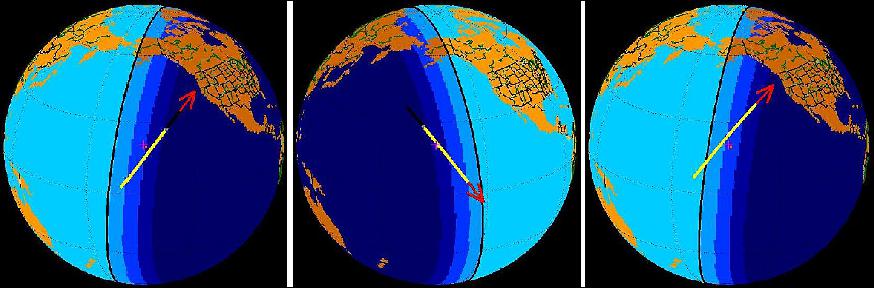
Pass Timing, Geometry and Object Illumination Details | |||
Pass Number | 1 | 2 | 3 |
Date | 2015-04-02 | 2015-04-02 | 2015-04-04 |
Rise | 05:21:18 - sunlit | 15:08:45 - umbra | 05:07:08 – sunlit |
Culmination (Max. El., Min. Range) | 05:26:28 - sunlit (44.7º, 547 km) | 15:13:58 - sunlit (81.6º, 394 km) | 05:12:20 - sunlit (51.5º, 496 km) |
Set | 05:31:38 - umbra | 15:19:10 – sunlit | 05:17:33 – sunlit |
Nominal Estimated SpinSat Command Execution Times | |||
LEDs ON | 05:23:51 | 15:11:21 | 05:09:34 |
LEDs OFF | 05:26:51 | 15:14:21 | 05:12:34 |
Thruster Firing | 05:27:06 | 15:14:36 | 05:12:49 |
LEDs ON | 05:27:21 | 15:14:51 | 05:13:04 |
LEDs OFF | 05:30:21 | 15:17:51 | 05:16:04 |
AMOS 3.6 m Telescope Sensors - Data Acquisition and Quality Summary | |||
LAAT (ACQ-WFOV) | good | good | not attempted |
DI (NFOV) | good | not attempted | not attempted |
ARDI (NFOV) | not attempted | good | not attempted |
LWIR (NFOV) | marginal | good | not attempted |
AMOS 1.6 m Telescope Sensors - Data Acquisition and Quality Summary | |||
AATS (ACQ-WFOV) | good | poor or none | good |
Flash (NFOV) | good | poor or none | good |
- Summary of AMOS Observations: Multiple sensors from the AMOS observatory's 3.6 m and 1.6 m telescopes were used to observe the three passes shown in Figure 14. Table 2 includes color-coded summaries of the status and quality for the collected data sets. The sensors include two acquisition sensors (LAAT and AATS) which are small, side-mounted, co-aligned telescopes imaging visible-band emissions using silicon-based CCD detectors, each with a relatively wide field-of-view (WFOV) subtending ~30 arcmin. The 3.6 m and 1.6 m telescopes also host one or more narrow field-of-view (NFOV) sensors, subtending ~30 arcsec or less. Three of these NFOV sensors (DI, ARDI, and Flash) also image in the visible and near-infrared spectral bands using Si-based CCDs. The 3.6 m LWIR sensor, however, acquires NFOV imagery in two thermal-infrared bands simultaneously. The analysis concentrates on the data gathered during the second AMOS pass, which had the best observing geometry and employed both near-IR and thermal-IR sensors from the largest-available AEOS (Advanced Electro-Optical System) 3.6 m telescope.
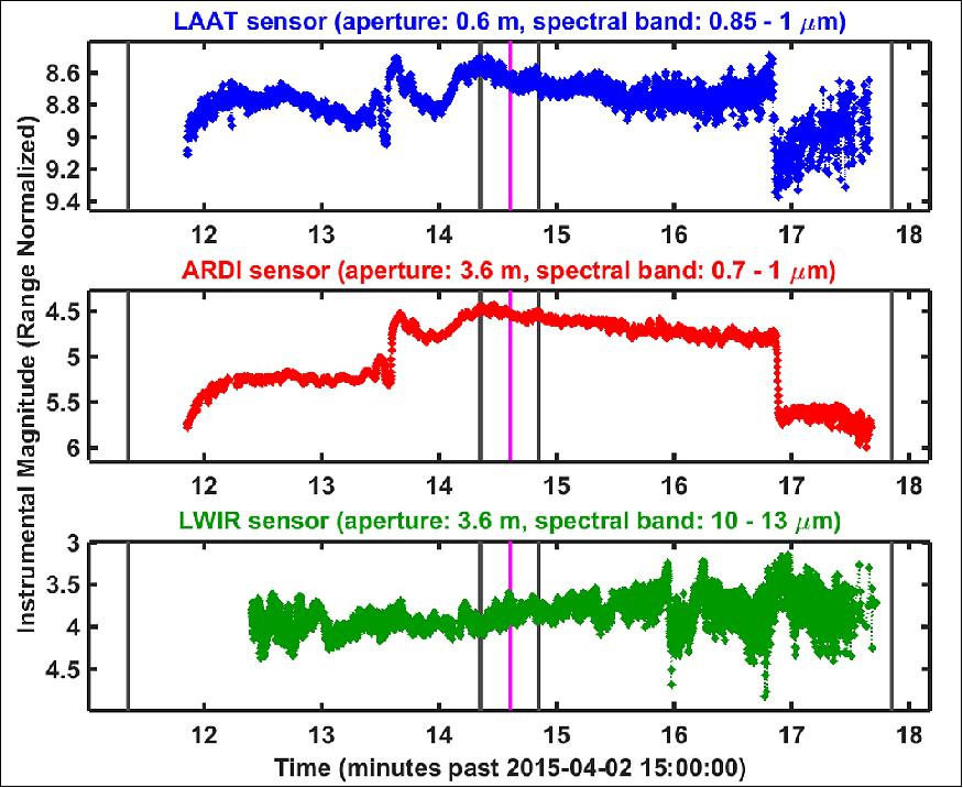
- Observed Light-Curves: Figure 15 shows three light-curve plots acquired by the AEOS telescope's LAAT, ARDI and LWIR sensors during the second AMOS pass. The brightness units are instrumental magnitudes normalized for range variations, which provide a logarithmic measure of whole-object brightness, with the effects of object-to-observer range variations removed (but otherwise not radiometrically calibrated). The upper panel (blue) shows data from the LAAT sensor (a 0.6 m acquisition telescope coaligned with the main 3.6 m telescope), within the approximate 0.85-1.0 µm spectral range using an 850 nm long-pass spectral filter. The middle panel (red) shows data from the ARDI sensor, which is mounted on the 3.6m telescope itself, measuring emissions in the ~0.7-1.0 µm range using an I-band filter; this sensor provided the best signal-to-noise quality data among all of the light-curve data. The bottom panel (green) shows data from one of the two channels of the narrow-field LWIR sensor, also mounted on the 3.6 m telescope, measuring thermal emissions in its N2 filter band spanning the ~10-13 µm spectral range.
- Figure 16 shows the light-curves along with these 1-minute-early event times. In this case, the increase in near-IR brightness at ~15:13:36 closely matches the 1-minute-early thruster firing, and the sudden dimming at ~15:16:52 closely matches the 1-minute-early LED deactivation. This compelling match prompts a hypothesis that an error occurred when entering, calculating or transmitting the event offset times.
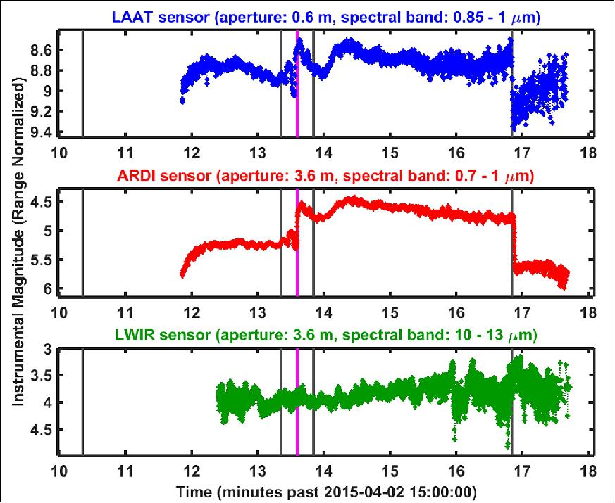
- The AMOS observations of SpinSat suggest that a timing error of exactly one minute likely occurred during the command-load uplink process. Otherwise the features of the AMOS light-curve data are difficult to explain. Based on this 1-minute-early assumption the following conclusions can be drawn from the data collected on 2015-04-02 and shown in Figures 16 and 17.
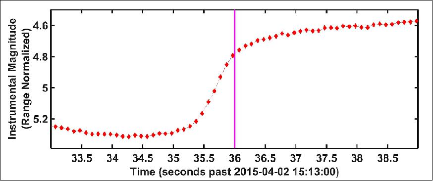
1) The ESP micro-thruster firing at ~15:13:36 caused a sudden near-IR brightening of ~0.5 magnitude.
2) The spatial signature of ESP micro-thrusters and/or their associated plumes were not detectable in the contrast-enhanced imagery from the narrow- and wide-field imaging sensors on the AEOS 3.6 m telescope.
3) The ESP thruster or LED on/off events were not detected in the thermal-IR imagery or the thermal-IR whole-object radiometry using the AEOS 3.6 m telescope LWIR instrument.
4) The LED deactivation at ~15:16:51 caused a sudden near-IR dimming of ~0.8 magnitude.
5) The preceding LED activation and deactivation events did not create comparable sudden brightness changes because, at the time of these command executions, the line of LEDs was likely oriented largely on the opposite side of the sphere than the AMOS sensors (Ref. 12).
• In June 2015, SpinSat is being tracked by the ILRS (International Laser Ranging Service) to provide total atmospheric density along the orbit track. 13)
• On Dec. 3, 2014, Andrew Nicholas of NRL made first contact with SpinSat. He sent the commands to start collecting data on the satellite's spin rate, as SpinSat continued its tumbling orbit around Earth. 14)
- SpinSat has 12 sets of six tiny thrusters that fire when they receive electric current, and can be fired in pairs to spin the satellite. And it's energy-efficient, according to NRL — using its primary batteries and 4.8 grams of "green" fuel, the thruster tests are expected to last six months.
- Meanwhile, SpinSat also will be used to test the SSN (Space Surveillance Network), the collection of ground-based radars and optical sensors around the world that tracks objects in space, partly with an eye toward preventing collisions.
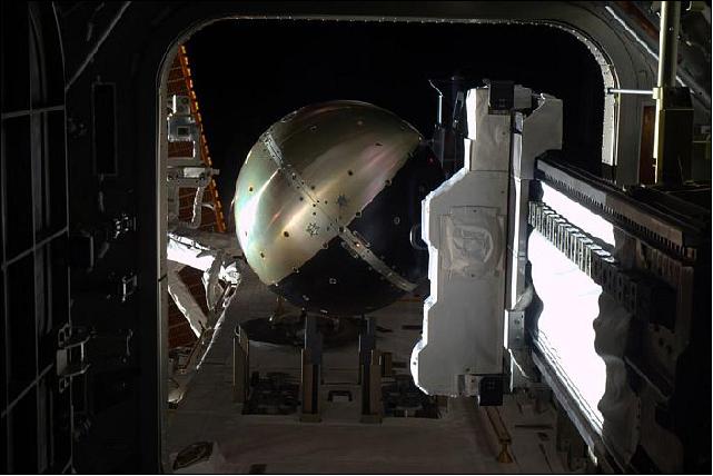
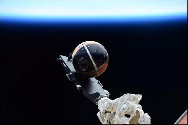
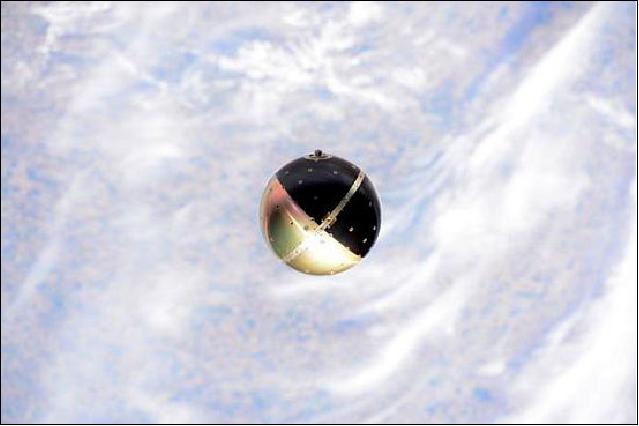
- The satellite's aluminum shell is coated with gold iridite and black anodized in four alternating sections (like a beach ball), and contains retroreflectors each made of three flat mirrors. NASA's ILRS (International Laser Ranging Service) will fire lasers at SpinSat, and the mirrors will reflect back to the ILRS, allowing scientists to determine its exact position and spin rate.
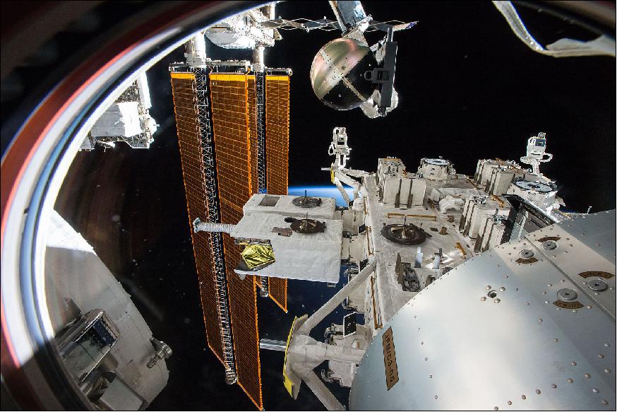
• Successful deployment of SpinSat, using the Cyclops deployment system, from the airlock of the JEM, took place on Nov. 28, 2014 at 14:30 UTC into a 400 km orbit at 51.65º inclination. This was the first time a new deployment mechanism was used on the ISS to pave the way for future deployments of satellites of different sizes and masses using the robotics system of the Space Station.
- For the deployment, the crew of the Space Station (Barry Wilmore and Terry Virts) installed the satellite on the Cyclops (SSIKLOPS) deployer using a single bracket. The deployer was then installed on the slide table of the Airlock of the JEM (Japanese Experiment Module) and necessary leak checks were completed before the outer hatch of the airlock was opened and the slide table was extended to allow the RMS (Remote Manipulator System) to grapple the Cyclops deployer. The arm was maneuvered to the proper position to release the satellite into a specific direction that ensures a safe departure path from ISS without any risk of re-contact on subsequent orbits. 15) 16)
- Once the SpinSat was deployed, the slide table was retracted and the outer hatch closed.
References
1) Andrew Nicholas, Ted Finne, Ivan Galysh, Anthony Mai, Jim Yen, Wayne Sawka, Jeff Ransdell, Shae Williams, "SpinSat Mission Overview," Proceedings of the 27th AIAA/USU Conference, Small Satellite Constellations, Logan, Utah, USA, Aug. 10-15, 2013, paper: SSC13-I-3, URL: http://digitalcommons.usu.edu/cgi/viewcontent.cgi?article=2911&context=smallsat
2) D. Newswander, J. Smith, C. Lamb, P. Ballard, "SSIKLOPS (Space Station Integrated Kinetic Launcher for Orbital Payload Systems) -Cyclops," FISO Telecon, March 9, 2014, URL: http://tinyurl.com/nq2yz7p
3) Andrew Nicholas, Ted Finne, Ivan Galysh, Anthony Mai, Jim Yen, Wayne Sawka, Jeff Ransdell, Shae Williams, Heather Cowardin, Aroh Barjatya, Forrest Gasdia, "SpinSat Mission Ground Truth Characterization," AMOS (Advanced Maui Optical and Space Surveillance Technologies Conference), Maui, Hawaii, USA, Sept. 9-12, 2014, URL: http://www.amostech.com/TechnicalPapers/2014/Poster/NICHOLAS.pdf
4) Wayne Sawka, M. McPherson, S. Williams, "Modular Solid Propulsion for CubeSat ACS and Delta-V Maneuvers," Proceedings of the 4S (Small Satellites Systems and Services) Symposium, Port Petro, Majorca Island, Spain, May 26-30, 2014
5) Kyra Wiens, "With SpinSat Mission, NRL Will Spin Small Satellite in Space with New Thruster Technology," NRL, Sept. 18, 2014, URL: http://www.nrl.navy.mil/media/news-releases/2014/with-spinsat-mission-nrl-will-spin-small-satellite-in-space-with-new-thruster-technology
6) Patrick Blau, "Dragon SpX-4 Cargo Overview," Spaceflight 101, URL: http://www.spaceflight101.com/dragon-spx-4-cargo-overview.html
7) Benjamin Romano, "Planetary Resources Inks 3D Systems Deal, Plans Test Launch From ISS," June 26, 2013, URL: http://www.xconomy.com/seattle/2013/06/26/planetary-resources-inks-3d-systems-deal-plans-test-launch-from-iss/
8) Daniel R. Newswander, James P. Smith, Craig R. Lamb, Perry G. Ballard, "Space Station Integrated Kinetic Launcher for Orbital Payload Systems (SSIKLOPS) – Cyclops," Proceedings of the 27th AIAA/USU Conference, Small Satellite Constellations, Logan, Utah, USA, Aug. 10-15, 2013, paper: SSC13-V-2, URL: http://digitalcommons.usu.edu/cgi/viewcontent.cgi?article=2941&context=smallsat
9) Daniel R. Newswander, James P. Smith, Craig R. Lamb, Perry G. Ballard, "Space Station Integrated Kinetic Launcher for Orbital Payload Systems (SSIKLOPS) – Cyclops," Proceedings of the 27th AIAA/USU Conference, Small Satellite Constellations, Logan, Utah, USA, Aug. 10-15, 2013, paper: SSC13-V-2, URL: http://digitalcommons.usu.edu/cgi/viewcontent.cgi?article=2941&context=smallsat
10) "Meet Space Station's Satellite Launcher Suite ‘Cyclops'," RedOrbit, April 4, 2014, URL: http://www.redorbit.com/news/space/1113113066/space-station%E2%80%99s-satellite-launcher-suite-cyclops-040414/
11) http://www.satview.org/?sat_id=40314U
12) Doyle Hall, Paul Kervin, Andrew Nicholas, Jake Griffiths, Ivan Galysh, Michael Werth, "Multi-sensor Observations of the SpinSat Satellite," Proceedings of the 16th AMOS (Advanced Maui Optical and Space Surveillance Technology Conference), Maui, Hawaii, USA, Sept. 15-18, 2015, URL: http://www.amostech.com/TechnicalPapers/2015/Poster/HallD.pdf
13) "ILRS Mission Priorities as of June 15, 2015," URL: http://ilrs.gsfc.nasa.gov/missions/mission_operations/priorities/
14) Kevin McCaney, "Navy's new 'beach ball' satellite takes a spin from the ISS," Defense Systems, Jan. 13, 2015, URL: http://defensesystems.com/articles/2015/01/13/nrl-spinsat-spherical-satellite-design.aspx
15) "Space Station Live: Cyclops Hits the Target," URL: https://www.youtube.com/watch?v=rQ9vJ5BCjUc
16) Patrick Blau, "SpinSat," Spaceflight 101, URL: http://www.spaceflight101.com/spinsat.html
17) Sarah Loff, "SpinSat Investigation Tests New Technology, Returns Data, NASA, May 21, 2015, URL: https://www.nasa.gov/image-feature/spinsat-investigation-tests-new-technology-returns-data
The information compiled and edited in this article was provided by Herbert J. Kramer from his documentation of: "Observation of the Earth and Its Environment: Survey of Missions and Sensors" (Springer Verlag) as well as many other sources after the publication of the 4th edition in 2002. Comments and corrections to this article are always welcome for further updates (eoportal@symbios.space).
Spacecraft Launch Sensor Complement Cyclops Deployer Mission Status References
Back to Top