Space Tethers
Non-EO
Quick facts
Overview
| Mission type | Non-EO |
Space Tethers
A space tether is a long cable used to couple spacecraft together as they orbit the central body (i.e. Earth). Tethers are usually made of thin strands of high-strength fibers such as Spectra or Kevlar. Any space tethered system is intimately connected to the gravitational force field. Conducting tethers offer the additional capability to interact with the magnetic and electrical force fields. 1) 2) 3) 4) 5) 6) 7)
The tethered system demonstrates gravity gradient attitude control. This is a very low cost attitude control system and if suitable for the mission, typically orients the system to within ±10 degrees of the vertical, both in and out the orbit plane.
Because the space tether makes it possible to transfer energy and momentum from one object to another, it can legitimately be called a form of space propulsion. There are two general categories of tethers. 8)
Momentum-exchange tethers (nonconductive tethers representing passive propulsion). They allow momentum to be transferred between objects in space, such as two spacecraft (tethers may redistribute momentum of a system from one body to another, but overall momentum is always conserved). The principle is based on the gravity gradient force.
Two objects, separated by a distance but tied together by a tether, are “pulled” apart by the gravity gradient force [this causes vertical (radial) alignment between the two objects]. Due to irregularities in the central body's gravitational field, the nearly radially aligned tether system actually librates, or oscillates, in a pendulum-like motion, about the system's center of mass. This swinging motion may be used to raise or lower the orbit of a tandem system without using any propellant.
- A tethered system release of an end-body from the remaining end-body and tether causes a momentum gain for the released end-body, resulting in a higher orbit for the released end-body orbit and a lower orbit for the remaining end-body and tether.
- A bolo tether rotates end-over-end in the orbit plane. This system could propel a payload attached to one end into a different orbit. The bolo could conceivably catch a payload.
- A stationary tether refers to two end-bodies connected by a tether of constant length. The system may be used to drag the lower end-body payload through the higher atmosphere (for sampling) and simultaneously lowering the system's orbit.
Electrodynamic tethers (conductive tethers representing active propulsion and power generation). An electrodynamic tether is essentially a long conducting wire extended from the main end-body (spacecraft). There may be a second end-body to help deploy the bare tether. The gravity gradient field of the “S/C and string system” tends to orient the tether in a vertical position. A tether in Earth orbit interacts with the Earth's magnetosphere due to the relative orbital velocities (in LEO systems the orbital velocity of the tether is greater than the rotational velocity of the geomagnetic field, this force is drag on the tether); the motion of the conductor across the magnetic field induces a voltage along the length of the tether. This voltage can be up to several hundred volts per km.
The interaction of the tether system with the magnetosphere can be used in the design of the system to act either as an “electrodynamic power or thrust system” to boost the orbit of the S/C; or it may be used to act as an “electrodynamic drag system” to lower the orbit of the S/C. The direction of the current flow in or out of an electrodynamic tether system determines if the interaction contributes to drag or to propulsion.
• Electrodynamic power or tether drag system. In this case the tether converts the orbital energy of the host S/C into electrical power. The drag force is used to decrease the orbit of the tether and its host S/C. In this design scheme current is produced by the interaction of the tether ends with the external plasma (a current loop consists of the tether, the external plasma, and the ionosphere). The collection of electrons from the plasma creates a net positive charge. This means that when electric power is generated by the tether for on-board use or simply for dissipation, it is generated at the expense of orbital energy.
• Electrodynamic thrust tether system. In this case, an EMF (Electromotive Force) acts to induce an electric potential along the tether system; the tether is used to boost the orbit of the host S/C. This concept requires power to be injected into the tether system from an on-board power supply, causing the system to gain altitude. The tether interaction with the Earth's magnetic field provides a “push” resulting in an orbit boost of the S/C.
A side effect of tether current flow is the production of electromagnetic waves (ULF, ELF, VLF) into the ionosphere, resulting from the electron transfer from the tether back into the plasma. This feature may give rise to use the tether also as an antenna.
Mission (Agency, institution) | Launch (Timeframe) | Orbit | Tether Length | Comment |
Gemini-11 (NASA) | Sept. 11-15, 1966 | LEO | 30 m | Spin-stabilized, 0.15 rpm |
Gemini-12 (NASA) | Nov. 11-15,1966 | LEO | 30 m | Local vertical, stable swing |
H-9M-69 | 1980 | Suborbital | 500 m | Partial deployment |
S-520-2 | 1981 | Suborbital | 500 m | Partial deployment |
CHARGE-1, (USA-Japan) | Aug. 8, 1983 | Suborbital | 500 m | Full deployment of conductive tether |
CHARGE-2 | Dec. 14, 1985 | Suborbital | 500 m | Full deployment |
ECHO-7 | Feb. 8, 1988 | Suborbital |
| Magnetic field aligned |
Oedipus-A (NRC/NASA,CRC, CSA) | Jan. 30, 1989 | Suborbital | 958 m | Spin-stabilized, 0.7 rpm (Canada/USA) |
CHARGE-2B | Mar. 29, 1992 | Suborbital | 500 m | Full deployment |
TSS-1 (STS-46) | Jul. 31-Aug. 8, 1992, | LEO | < 270 m | Electrodynamic tether, partial upward deployment and retrieval of tether |
SEDS-1 (NASA) | Mar. 29,1993 | LEO | 20 km | Nonconducting tether, downward deployment, swing and cut |
PMG (DoD) | Jun. 26, 1993 | LEO | 500 m | Electrodynamic tether, upward deployment, tether current in both directions. Demonstration of hollow cathode plasma contactors for current collection and emission |
SEDS-2 (NASA) | Mar. 9, 1994 | LEO | 20 km | Local vertical stable, downward deployment. SEDS-2 proved that one can accurately deploy a tether to a stable vertical position by feedback control with a simple friction brake. |
Oedipus-C (NRC/NASA,CRC, CSA) | Nov. 7, 1995 | Suborbital | 1 km | Spin-stabilized, 0.7 rpm (Canada/USA) |
TSS-1R (STS-75) | Feb. 22-Mar. 9, 1996 | LEO | 19.6 km | Electrodynamic tether severed prior to full deployment |
TiPS (NRO/NRL) | May 12, 1996 Jun. 20, 1996 deployment | LEO | 4 km | Long life tether (tracking of > year) |
YES (ESA and Delta-Utec) | Oct. 30, 1997 | GTO | 35 km | YES (of TEAMSAT) was not deployed to avoid a collision risk with other S/C |
STEX/ATEx (NRO/NRL) | Oct. 3, 1998 | LEO | 6 km | Nonconductive tether, demonstration of tether system stability and control. However, a deployment malfunction caused a failure of the experiment |
PICOSAT1.0 of the Aerospace Corporation | Jan. 27, 2000 on OPAL of Stanford | LEO | 30 m | PICOSAT1.0 was ejected OPAL on Feb 6, 2000. The system of two S/C operated for 3 days when battery power decayed. |
PICOSAT1.1 of the Aerospace Corporation | July 19, 2000 on MightySat II.1 of AFRL | LEO | 30 m | PICOSAT1.1 was ejected successfully from Mightysat II.1 13 months after launch (Sept. 2001) to test storage effects on the system. |
ProSEDS (NASA) | ProSEDS was cancelled in 2003 | LEO | 25 km | Upward deployment (producing drag and electrical power) |
MAST (TUI, Stanford) | April 17, 2007 | LEO | 1 km | Deployment of 3 CubeSats. However, only a few meters of deployment could be achieved. |
YES2 (ESA and Delta-Utec SRC) | Sept. 14, 2007 | LEO | 31.7 km | Experimental data show (post flight analysis) that the momentum exchange tether successfully deployed to its full length of 31.7 km. |
The drag feature of tethers may be used to deorbit a body (a malfunctioning or out-of-service satellite). A multitude of low-cost applications can be designed around tether systems besides propulsion (such as communications, atmospheric studies, gravity experiments, power generation, etc). 9)
Overview
Early ideas on space tethers can be traced to the works of the Russian space enthusiast Konstantin Tsiolkovsky (1857-1935). In 1895 Tsiolkovsky became fascinated with the construction of the tall Eiffel Tower (300 m) which was inaugurated in 1889 on the occasion of the first World Exposition (Exposition Universelle) in Paris, France. He imagined an immensely taller tower reaching into space, with a “celestial castle” at the top. He proposed a conceptual tower so tall that it reached into space, held there by the rotation of the Earth. However, there was no realistic way to build it (Ref. 6).
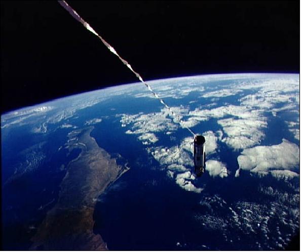
The first two space tethers (each 30 m in length) flew in 1966, during the Gemini-11 and -12 manned orbital missions of NASA. Each Gemini spacecraft was tethered to its Agena upper stage. They created a milligee of artificial gravity and discovered the awkward dynamics. The control by humans was seen as a way to simplify the system rather than complicate it!
The 3-day mission (launch of Gemini-11 on Sept. 12, 1966) was designed to achieve a first orbit rendezvous and docking with the Agena target vehicle, accomplish two EVA (Extra Vehicular Activity) tests, perform docking practice, docked configuration maneuvers, tethered operations, parking of the Agena target vehicle, and demonstrate an automatic reentry.
The first space tethers were webbed lines that connected the Gemini-11 and -12 spacecraft (launch of Gemini-12 on Nov. 11, 1966) to their Agena docking targets on separate missions in 1966. These demonstrated that tethers could be used to connect spacecraft for artificial gravity or to stabilize a spacecraft.
Orbital tether experiments began again in 1980 and have continued through the present. Tether missions in the 1990s have included several important milestones, such as: (see also Table 1). The finding of the proper deployment strategy and mechanism has been the biggest problem throughout the history of space tethers so far - resulting in many mission failures.
• First retrieval of a tether in space (TSS-1, 1992)
• Successful deployment of tethers 20 km long (SEDS-1, 1993) 10)
• First operation of an electrodynamic tether (PMG, 1993) with current driven in both power mode and thrust mode.
• The TiPS mission (launch 1996) provided the longest survival time in space so far (> 6 1/2 years)
• The YES2 mission (launch 2007) deployed the longest tether so far (31.7 km) and delivered a Spacemail probe to the ground.
Tether Missions/Experiments
The various spaceborne mission short descriptions are listed in alphabetical order of the acronym. 11) 12)
• Some missions listed in Table 1 (STEX/ATEx, YES2) are separately described on the eoPortal.
• The PICOSAT payloads ares described under the OPAL mission on the eoPortal.
MAST (Multi-Application Survivable Tether)
MAST is a collaborative CubeSat project of TUI (Tethers Unlimited Inc.) of Lynnwood, WA (USA) and SSDL (Space Systems Development Laboratory) of Stanford University, Stanford, CA. The overall objective of the tether demonstration mission is to obtain data on tether performance, survivability, and dynamics. The data is crucial to the development of operational tether systems for propellantless propulsion and deorbit, formation-flying, and momentum-exchange transportation applications. In particular, detailed on-orbit data on the survivability of space tethers and other gossamer spacecraft structures in the micrometeorite/orbital debris (M/OD) environment is of prime importance. 13) 14)
The MAST program has been funded through a combination of private and government research funds. The development of the underlying technologies was funded by a NASA Small Business Technology Transfer (STTR) contract, with Stanford University's SSDL collaborating as the non-profit Research Institution.
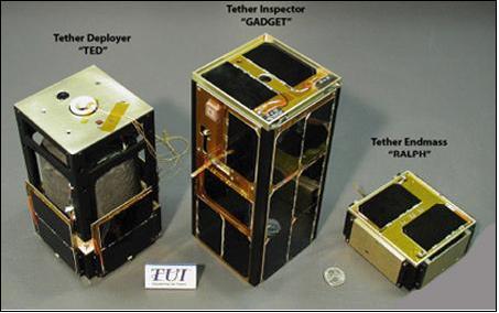
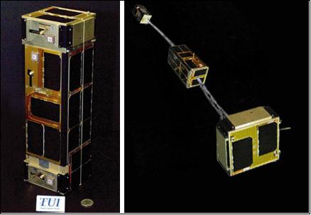
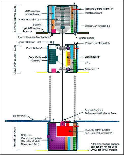
The MAST experiment consists of three picosatellites, (i.e. a triple CubeSat configuration, stacked into a single P-POD) with the following labels: a) TED (Tether Deployer) satellite, with a 1 km deployable multi-strand Hoytether; b) RALPH, a small end mass satellite; and between them, c) GADGET, an inspector satellite which could move along the tether. The tether structure is composed of the multi-strand Hoytether( with redundant interlinking that is able to withstand many impacts) that incorporates both conducting and nonconducting materials. Each end of the tether will be anchored with a picosatellite.
After deployment, the middle CubeSat, referred to as “Gadget”, will slowly crawl up and down the tether, inspecting and scanning it for damage due to M/OD impacts and AO (Atomic Oxygen) degradation. The imagery of the tether will be transmitted periodically to a ground station for analysis. In addition, all three picosatellites contain GPS receivers, and data from these receivers will be collected to provide information on the dynamics of tethered formations of spacecraft and the performance of the tether deployment technologies. 15)
Launch
The fourth multiple-launch CubeSat mission took place on April 17, 2007 from the Baikonur Cosmodrome, Kazakhstan on a Dnepr launch vehicle (launch provider: ISC Kosmotras). The launch involved 7 CubeSats and 7 microsatellites as secondary payloads.
Orbit: Sun-synchronous orbit, average altitude of ~ 700 km, inclination = 98º, LTAN (Local Time on Ascending Node) is at 22.30 hours UTC.
MAST Tether Deployment Status
• On April 20, 2007, TUI engineers were able in making contact with the 'Gadget' picosatellite during two passes over the ground station. 16)
• During the pass of April 23, TUI engineers were again able to establish excellent contact with Gadget. Contact with TED (Tether Deployer) could not be made. Gadget downlinked a test photo of the tether taken soon after the PPOD deployer ejected MAST into orbit.
• April 30, 2007: Based upon TUI's preliminary analysis of the data received from Gadget, TUI engineers are confident that TED has separated from Gadget and at least a short portion of the tether has deployed. - But somehow, a glitch in the restraint system kept TED from pushing away hard enough to keep unreeling the tether from its spool. Hence, the tether deployed just a few meters rather than its full length of 1 km.
• May 9, 2007: The downlink communications with Gadget improved considerably.
In short, the trio of MAST picosatellites has failed in an attempt to deploy a 1 km long tether in space. 17)
OEDIPUS - Tethered Sounding Rocket Missions
Various Canadian organizations [NRC (National Research Council) of Canada, CRC (Communications Research Center) of Ottawa, and CSA (Canadian Space Agency)] have successfully deployed two tethered systems from sounding rockets. These suborbital missions for “Observations of Electric-field Distribution in the Ionospheric Plasma - a Unique Strategy” were accomplished as OEDIPUS-A in January 1989 and OEDIPUS-C in November 1995.
OEDIPUS-A
OEDIPUS-A was designed as a large double probe for sensitive measurements of weak electric fields in the plasma of the aurora. It was launched on January 30, 1989 as a CSA space physics mission undertaken in cooperation with NASA. OEDIPUS-A was launched on a 3-stage Black-Brant 10 sounding rocket from the Andoya Rocket Range in Norway.
The principle scientific objectives of the mission were to make electric field, electric wave, magnetic field and particle measurements in the earth's ionosphere up to an altitude of 600 km.. The tethered payload consisted of two spinning sub-payloads with a mass of 84 and 131 kg, with their own experiment complement and telemetry systems, that were connected by a thin 0.85 mm diameter conductive and also spinning tether. The mission achieved its scientific objectives to detect the natural magnetic-field-aligned dc electric field E utilizing a large double probe, and to carry out novel bistatic propagation experiments. The flight established a record for the length of an electrodynamic tether in space at that time: 958 m.
Although the mission was successful, flight data indicated that the aft sub-payload experienced a rapid increase in its coning angle to nearly 35 degrees (half angle). A post-flight investigations concluded that the dynamic behavior was caused by interaction of the tether with the sub-payloads. This observation was unexpected due the fact that the tether mass was negligible relative to masses of both sub-payloads, and the tether dynamic interaction was expected to be negligible in the relatively short time (11 minutes) of a suborbital flight.
OEDIPUS-C
OEDIPUS-C was flown on a 4-stage Black Brant 12 vehicle launched from the Poker Flat Research Range in Alaska (launch on Nov. 7, 1995; apogee of 869 km). The science objectives were to study the natural and artificial waves in the ionospheric plasma as well as the dynamics of a spinning tethered space system. The OEDIPUS-C payload was sponsored by the CSA and the payload contractor was Bristol Aerospace Ltd. of Winnipeg.
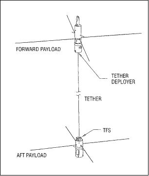
OEDIPUS-C has two spinning payloads connected by a conducting tether of ~ 1,200 m in length. During the flight's upleg the magnetically aligned tether was deployed to its full length and then cut at both ends. The forward payload contained a 50 kHz to 8 MHz stepped-frequency transmitter. Receivers were carried on both forward and aft payloads. The transmitter swept through the frequency range every 0.5 s. During each of the 3-ms steps the transmitter emitted only for the first 0.3 ms.
The TFS (Tether Force Sensor) provided new insights into the complicated dynamic motion of the tethered double payload. The TCM (Tether Current Monitor) instrument operated the two sub-payloads and the conducting tether as a double electrostatic probe. During the flight upleg experiment, the angle between the tether and the geomagnetic-field direction was less than 5º. The TCM configured the payload cyclically as a high-impedance voltage probe and as a low-impedance current probe. 18) 19)
The mission provided perspectives on plane and sheath waves and their interaction with space plasma. The science experiments were also designed to help to understand how charged particles associated with aurora affect satellite transmissions. 20
PMG (Plasma Motor Generator)
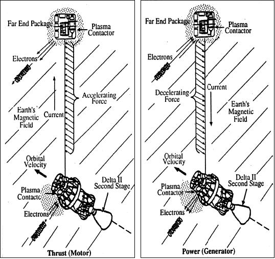
PMG is a NASA tether payload on a DoD satellite that was launched as a secondary payload on a Delta-2 launch vehicle on June 26, 1993. The 500 m long tether was chosen to assure complete separation between the grounded ends, forcing current closure through the ionosphere rather than with local overlap of the two plasma clouds.
The objectives of PMG were to test: 1) the performance of the HCA (Hollow Cathode Assembly) to provide a low impedance bipolar electrical current between a spacecraft and the ionosphere, and 2) demonstrate the functions of space propulsion and electrical current generation (and current reversal in tether using a bias voltage).
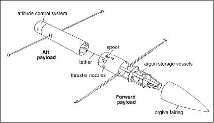
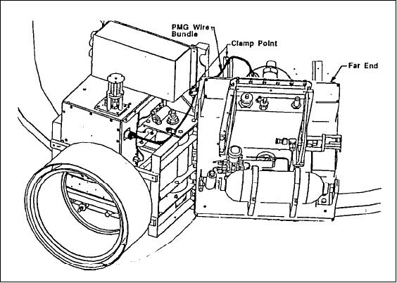
The PMG consisted of four basic elements: FEP (Far-End Package), NEP (Near-End Package), an electronics box called SEDS (Small Expendable Deployer System), and PDP (Plasma Diagnostic Package) of NASA/LeRC.
The tether was 500 m in length and consisted of a number 18 AWG (American Wire Gauge) Teflon-insulated copper wire. PMG was “SEDS-like” in deploying off the end of a fixed spool, but the much heavier, stiffer wire and limitations on available space required a short, fat deployer and elimination of the active brake. Passive braking was provided by winding the innermost layer of wire onto a weak adhesive coating on the deployer core. The PMG used the NASA/MSFC-developed SEDS computer to store and format data for telemetry.
After third-stage separation, the PMG was left in an elliptical orbit (193 km x 869 km, inclination = 25.7º). The FEP was ejected upward with an initial velocity of 2-3 m/s. Each HCA was equipped with a 1 liter gas bottle, on/off solenoid, gas metering block power supplies to produce a weekly ionized xenon cloud. Both end platforms carried a 28 V silver cell battery for a nominal lifetime of 3-6 hours. 21) 22) 23)
The PMG current showed to be fully reversible, operating either as a generator system (de-boost) with electron current flow down the tether, or as a motor (boost) with electron current driven up the tether. The induced EMF was measured with total voltage biased from +150 to -90 V, and also with the bias turned off by using only the induced EMF.
The PMG flight demonstration proved the ability of the proposed Space Station plasma grounding techniques for maintaining the electrostatic potential between the Space Station and the surrounding plasma medium. The PMG also demonstrated the ability to use electrostatic tethers to provide thrust to offset drag in LEO space systems. In addition, the PMG demonstrated the use of direct magnetic (non-rocket) propulsion for orbital maneuvering.
ProSEDS (Propulsive Small Expendable Deployer System)
A NASA/MSFC tether demonstration experiment, planned to fly in 2003 (the launches have been postponed several times). ProSEDS is based on the SEDS deployment scheme, with the objective to deploy an electrodynamic tether from a Delta-II rocket's third stage (launching a GPS satellite) to achieve about 1 N drag thrust for stage deorbiting. The tether is composed of 10 km of nonconducting Spectra tether for ballast and to begin the deployment, and of a 5 km of aluminum wire (1.2 mm diameter), simply a bare wire. The interaction of the bare-wire tether with the space environment will generate an electrical current (or a thrust that might be used by the S/C); hence, ProSEDS will turn itself into an electromagnetic brake by lowering its altitude. An orbital decay of at least 5-15 km in altitude per day is expected with this deorbiting technique. It's not quick compared to a retrorocket, but it is much faster than natural decay. And it's being done without the use of any propellant. 24) 25)
Orbit: circular orbit, altitude = 400 km, inclination = 35º
Note: ProSEDS was to fly in 2003, but after the Columbia tragedy NASA re-evaluated several missions and decided that ProSEDS posed too great a risk to the International Space Station (ISS).
SEDS (Small Expendable Deployer System)
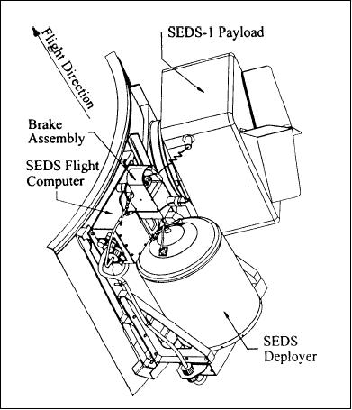
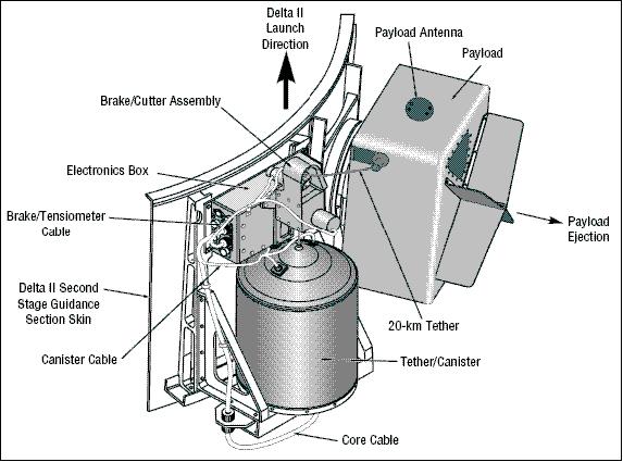
SEDS is a NASA/MSFC tether experiment demonstration program, developed by MSFC and by Tether Applications Co. of San Diego. Two flight experiments (nonconducting momentum-exchange tethers) have been flown as Delta secondary payloads on the second stage of GPS satellite launches. Each SEDS subsatellite was deployed by means of a deployer system. 26)
SEDS was conceived as a complement to the NASA TSS (Tethered Satellite System), for cases in which tether retrieval is not needed. Simulations showed that deployment at low tension had two significant benefits in payload boosting or de-boosting: it allowed use of a simpler brake, and it induced a wide libration that nearly doubled the ΔV provided by a given length of tether.
SEDS-1
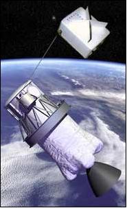
SEDS-1, launched March 29, 1993 (NavStar-2A 10), was a 20 km (tether of 0.75 mm diameter) downward deployment with the objective to demonstrate the use of a tether to place a payload in a deorbit trajectory (study of reentry after the tether was cut). The Delta second stage was in an elliptical orbit (195 km x 705 km, inclination of 34º), the tether deployment was initiated at apogee.
An hour after launch a spring loaded Marman clamp ejected a 26 kg payload downward at 1.6 m/s. This impulse was sufficient to allow deployment of enough tether for gravity gradient effects to take over and guarantee the remainder of deployment. Once into this regime, the tether paid off the end of a fixed spool inside the deployer at an increasing rate. Passive effects caused a smooth rise in tension as the tether unwound faster and faster from a shrinking package. Finally, when 1 km of tether remained, active braking was applied by wrapping the tether around the ”barber pole” brake.
The physical connection of the payload to the upper stage by the tether forced the payload to orbit the Earth with the same velocity as the upper stage. At the payload's location, 20 km closer to the Earth, however, this velocity was less than that required for the payload to remain in orbit. After completion of the deployment, the tether was released from the upper stage. This dropped the payload into a suborbital trajectory that reentered the Earth's atmosphere half an orbit later. 27)
Telemetry was obtained from the deployer through the Delta second stage telemetry system and from the tether end-mass via an S-band transmitter. The deployment took about one orbit and the tether brake was applied. The tether with its end-body payload swung to local vertical at which time the tether was cut at the deployer end and the end-body, trailing the tether, reentered the atmosphere and burned to destruction off the coast of Mexico. The reentry was video taped by a team of observers.
SEDS-2
SEDS-2, launched on March 9, 1994 (NavStar-2A 15, the last GPS Block 2 satellite launch), was also a 20 km downward deployment, but the mission objective was to demonstrate the use of a modified SEDS to deploy and stabilize a tether system along the local vertical. The orbit of the second stage was circular at an altitude of 350 km.
SEDS-2 used feedback braking starting early in deployment. This limited the residual swing after deployment to 4º. Mission success was defined as deployment of at least 18 km, plus a residual swing angle < 15º. The payload returned data for 8 hours until its battery died; during this time tether torques spun it up to 4 rpm.
The 19.7 km tether was left attached to the Delta second stage to determine long-term tether stability and micrometeoroid risks. However, the tether suffered a cut 3.7 days after deployment. The tether was very probably cut by a micrometeoroid or by space debris. Approximately 7.2 km of tether remained attached to the Delta second stage until reentry into the atmosphere two months later (May 14, 1994). Surprisingly, the tether was an easy naked eye object when front lit by the sun and viewed against a dark sky. Intensified videos were made of more than 20 passes over a 7 week period; all showed the tether stabilized near the vertical, even after the cut when tension was < 4 grams. Ref. 10) 28) 29)
For both payloads, the end-body instrument package was designed and built by LaRC. It consisted of a three-axis tensiometer, a three-axis magnetometer, and a three-axis accelerometer. The end-body measured tether system performance and end-body attitude.
TiPS (Tether Physics and Survivability)
TiPS is a low-budget quick reaction experiment (a secondary payload) sponsored by NRO [National Reconnaissance Office (of DoD, USA)].
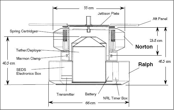
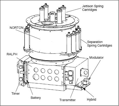
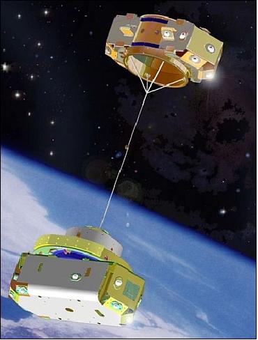
The TiPS payload consists of two end-bodies (of box-like shape, each covered with 18 laser retroreflectors), with a total mass of 54 kg [37.7 kg for the larger box (dubbed `Ralph') and 10.8 kg for the smaller upper box (dubbed `Norton'), tether mass of 5.5 kg], were separated by 4 km of a nonconducting tether. The cylindrical shape of the tether is due to strands of Spectra woven around yarn. Ralph contains a SEDS (Small Expendable Tether Deployer System) box from NASA/GSFC which in turn contains all the electronic components (telemetry system, turn-count recorder, and temperature sensors). 30)
The telemetry system is powered by a non-rechargeable battery, which operated for the first eight hours of the satellite's life after deployment. Telemetry generated during the separation of the two end-bodies confirmed full tether deployment. NRL, NASA and an international network of SLR (Satellite Laser Ranging) stations (in addition ground-based radar data and optical data from several telescopes) provided global tracking of the system for the duration of one year (history of the librational and rotation motion dynamics).
Note: Ralph and Norton are two characters of the Honeymooner's television fame (mainly during the 1950-60s), representing adequately the satellite mass ratio.
Retroreflectors are mounted on the exterior surfaces of both Ralph and Norton, for long-term passive monitoring of the tethered system. End-body discrimination is accomplished by coating the retroreflectors of Ralph to reflect only one of the two transmitted laser wavelengths. The uncoated retroreflectors on Norton reflect both transmitted wavelengths.
Launch
TiPS was launched May 12, 1996 on a DoD satellite from VAFB, CA (Titan-4 vehicle), and deployed on June 20, 1996 [built and operated by NCST (Naval Center for Space Technology) of NRL]. The experiment objective is to increase knowledge about gravity-gradient tether dynamics and the long-term survivability of tethers in space. A deployment sequence jettisoned the TiPS satellite from a host vehicle and then separated its two end-bodies from each other (initial separation velocity of 5.1 m/s). 31) 32) 33)
Orbit: Near-circular orbit, mean altitude = 1022 km, inclination = 63.4º, period = 105 min.
The TiPS orientation is controlled by gravity gradient forces. The passive TiPS satellite orbits the Earth with a nominal vertical orientation, with Ralph closest to the Earth. About this nominal orientation, the tethered system undergoes libration. The various tracking information was used to determine the orbit and attitude of the tethered system. The most significant finding from the experiment was that the attitude and rotational motions of the tether system have damped significantly since initial deployment (from about 40º in-plane and 33º cross-plane to about 7.5º and 5º - 7º, respectively). 34)
Note: The two TiPS end masses, Ralph and Norton, are equipped with retroreflector arrays. This feature permitted the SLR (Satellite Laser Ranging) tracking services provided by ILRS.
Tether length, nominal diameter | 4023 m, 2 mm (approximately) |
Tether construction (made by AlliedSignal) | The outer layer is Spectra 1000 braid for strength, the core is acrylic yarn which will puff the other braid out to the 2mm diameter and give it a larger cross section to improve its resistance to debris and small micrometeoroids. |
Tether breaking strength | 90 kg (approximately) |
TiPS total mass | 54 kg |
Mass of Ralph (lower end body) | 37.7 kg |
Mass of Norton (upper end body) | 10.8 kg |
Mass of tether | 5.5 kg |
TiPS initial spin rate | 4 rpm |
Mission Status
In late 2003, TiPS was still surviving the hazards of space after more than 6 1/2 years, connecting two spacecraft in an orbit at ~ 1000 km altitude. The high strength polymer used in the TiPS tether is a braided spectra sheath (SpectraTM 2000) surrounding an acrylic yarn core. The low-cost demonstrator mission provided valuable engineering data to validate complex models of the structural response of tethered satellites. 35)
TSS (Tethered Satellite System)
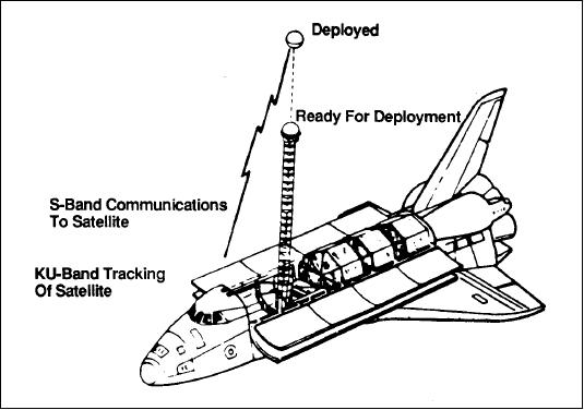
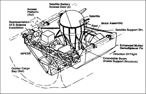
TSS is a cooperative program of ASI (Italian Space Agency) and NASA for a reusable multi-disciplinary facility to conduct space experiments in Earth orbit. The system consists of a satellite, a conductive tether (approx. 20 km long) and a deployer in the Shuttle's cargo bay.
Background: The TSS program traces its birth to 1974 when Guiseppe Colombo of Padua University (Italy) came up with the idea of using a long tether to support a satellite from an orbiting platform. Later in the 1970s, G. Colombo and Mario Grossi of the Smithsonian Astrophysical Laboratory (SAO), Cambridge MA, proposed a mission to study the possible scientific applications for long tethers in space. A NASA-ASI memorandum of understanding was signed in 1984, in which NASA agreed to develop a deployer system and tether, and ASI agreed to develop a special satellite for deployment.
TSS-1 (Tethered Satellite System-1)
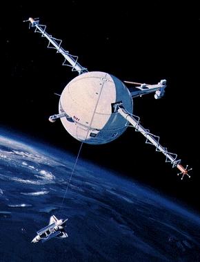
TSS-1 consisted of a satellite, a conducting tether, and a tether deployment/retrieval system, the mission was conducted on space shuttle flight STS-46, July 31 - Aug. 8, 1992.
The objectives of the TSS-1 mission were to: 1) demonstrate/verify the feasibility of deploying and controlling long tethers in space, and to 2) to evaluate some of the unique applications of the TSS as a tool for research by conducting exploratory experiments in space plasma physics. 36)
On orbit, an electrically conductive satellite (TSS-1), a sphere of 1.6 m diameter with a mass of 518 kg, was deployed; it was tethered to the Orbiter by a conductive tether (2.54 mm diameter using Kevlar and Nomex with 10 strands of 34 AWG copper wire and a Teflon sheath). A maximum upward separation of 267 m between the Orbiter and satellite was achieved. A protruding bolt had prevented full release of the tether during the TSS-1 mission. - Several unsuccessful attempts were made to extend the tether to its full planned extension of 20 km. Deployed operations lasted nearly one full 24 hour period - then the tether was retrieved. Even though the primary mission goals were not achieved many interesting results were obtained.
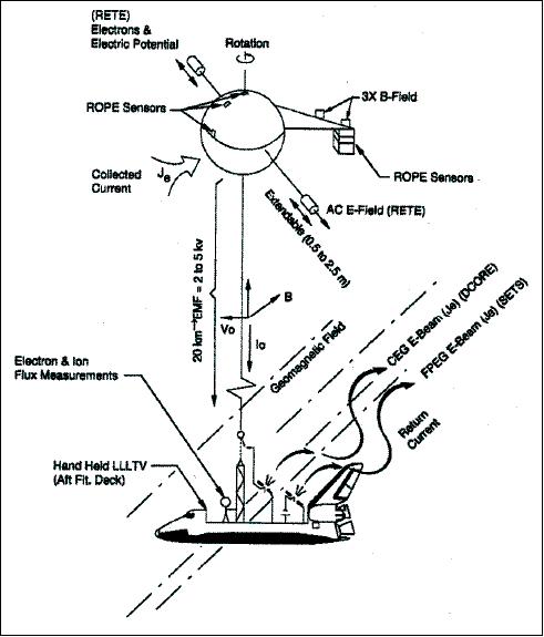
The SETS (Shuttle Electrodynamic Tether System) was one of several instrument packages included in TSS-1. It includes five instruments, a flight computer, and a power interface box. TCVM (Tether Current Voltage Monitor) measured the tether current and voltage. FPEG (Fast Pulsed Electron Gun) provided removal of negative charge from the Orbiter electrical ground. The CCP (Charge Current Probe) used a dual-sensor combination to measure the differential changes in the vehicle potential and return current from the ionosphere to the Orbiter structure. The SRPA/LP (Spherical Retarding Potential Analyzer and Langmuir Probe) instrument determined the thermal plasma characteristics relative to the ionosphere. AMAG (Aspect Magnetometer) measured the magnetic field in the Orbiter's payload bay.
TSS-1R (TSS-1 Reflight) mission
TSS-1R, flew on space shuttle flight STS-75 Feb. 22 - March 9, 1996. During the flight, the Tethered Satellite was deployed to a distance of 19.7 km (goal of 20.7 km) while science data was collected aboard the satellite, the space-shuttle orbiter, and from a network of ground stations monitoring the Earth's ionosphere.
However, the TSS-1R mission suffered a broken tether (the cable suddenly snapped near the top of the deployment boom, it was burned through by an electrical arc prior to maximum deployment of 20.7 km). Tether dynamics were verified up to a length of 19.7 km providing a total of five hours of deployed electrodynamic measurements (largest man-made electrodynamic structure placed in orbit so far).
Experiments: (Ref. 4)
ROPE (Research on Orbital Plasma Electrodynamics): An investigation to study the behavior of the ambient ionospheric charged particle populations and of ionized neutral particles around the TSS-1R satellite under a variety of conditions (study of the physics of tether current production).
RETE (Research on Electrodynamic Tether Effects): This investigation provides a profile of the electrical potential in the plasma sheath and identifies waves excited by this potential in the region around the satellite. The instruments are mounted in two canisters at the end of a pair of 2.4 m extendible booms. As the satellite spins, the booms are extended, and sensors measure electric and magnetic fields, particle density, and temperature at various angles and distances in the equatorial plane of the satellite.
One boom carries a wave sensor canister, which contains a three-axis ac electric field meter and a two-axis search coil ac magnetometer to identify electric fields and electrostatic waves and to characterize the intensity of surrounding magnetic fields.
On the opposite boom, a plasma package determines electron density, plasma potential, and low-frequency fluctuations in electric fields around the satellite. A Langmuir probe with two metallic sensors samples the plasma current; from this measurement, plasma density, electron temperature, and plasma potential may be determined. This potential is then compared to that of the satellite. Two other probes measure low frequency electric fields.
TEMAG (Magnetic Field Experiment for TSS Missions): Study of the magnetic field in the satellite vicinity. Two triaxial fluxgate magnetometers, very accurate devices designed to measure magnetic field fluctuations, are located on the fixed boom. One sensor at the tip of the boom and another at mid-boom characterize ionospheric conditions at two distances from the satellite, determining the magnetic signature that is produced as the satellite moves rapidly through the ionosphere.
SETS (Shuttle Electrodynamic Tether System): This investigation is designed to study the current-voltage characteristics of the orbiter-tether-satellite system and the fundamental controlling parameters in the Earth's ionosphere. This is accomplished through control of the tether system electrical load impedance and the emission of electrons at the orbiter end of the system. The experiment also explores the use of space tethers as science tools.
SPREE (Shuttle Potential and Return Electron Experiment): The objective is to measure the charged particle populations around the orbiter for ambient space conditions and during active TSS-1R operations. SPREE supports the TSS-1R electrodynamic mission by determining the level of orbiter charging with respect to the ambient space plasma, by characterizing the particles returning to the orbiter as a result of TSS-1R electron beam operation, and by investigating local wave particle interactions produced by TSS-1R operations.
TOP (Tether Optical Phenomena Experiment): TOP is a hand-held camera system with image intensifiers and special filters. The objective is to provide visual data that may allow scientists to answer a variety of questions concerning tether dynamics and optical effects generated by the TSS-1R.
EMET (Investigation of Electromagnetic Emissions by the Electrodynamic Tether):
The goal of the TSS-1R mission was to demonstrate some of the unique applications of the TSS as a tool for research by conducting exploratory experiments in space plasma physics. It was anticipated that the motion of a long conducting tether through the Earth's magnetic field would create a large motional emf that would bias the satellite to high voltages and drive a current through the tether system. The circuit for the tether current would be closed by a large external loop in the conducting ionospheric plasma where an array of physical phenomena and processes would be generated for controlled studies.
The deployment of 19.7 km was sufficient to generate high voltages across the tether and extract large currents from the ionosphere. These voltages and currents, in turn, excited several space plasma phenomena and processes of interest. A high-quality data set was gathered prior to tether failure.
Both TSS missions confirmed concept validation of long gravity-gradient tethers; moreover the data gathered during the second mission confirmed the possibility to use the system for the conversion of orbital energy to electrical energy. 37) 38)
YES (Young Engineers' Satellite)
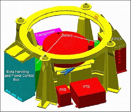
YES was an ESA student project, consisting of 2 free-flying satellites: the Young Engineers' Satellite with a mass of 180 kg, and the 12 kg TORI (Tethered ORbit Insertable). YES has been the initiative and responsibility of young engineers and students at Delta-Utec Space Research (Leiden, The Netherlands) and at ESA/ESTEC, and was partly financed by the Dutch government. The overall objective was a technology demonstration, namely to study the dynamics of tethered satellites.
YES itself was a payload on the low-cost satellite demonstrator mission, namely TEAMSAT(Technology, science and Education experiments Added to Maqsat) of ESA, the first S/C delivered to orbit by the Ariane-5 launcher on its second qualification flight. The TEAMSAT spacecraft turned out to be an embedded payload (350 kg) of the Ariane-5 upper instrumented test platform, referred to as Maqsat-H, carrying five experiments provided by various European universities. 39) 40) 41)
Launch
The launch of MaqSat-H + (TEAMSAT and YES) on Ariane-5 took place on Oct. 30, 1997 from Kourou.
Orbit of MaqSat-H, TEAMSAT and YES: GTO (Geostationary Transfer Orbit) achieved: Perigee = 525 km, apogee = 27,000 km, inclination = 7.76º, period = 7 hours, 40 minutes.
YES Payload
YES was a free-flying subsatellite of TEAMSAT, intended to deploy a 35 km tether attached to an inert counter-balance mass of 12 kg, referred to as TORI (Tethered Orbit Insertable), to study the dynamics of tethered satellites. YES was physically the lid of the TEAMSAT box, requiring ejection prior to becoming a free-flier.
The primary objective was to investigate tether deployment and dynamics in GTO, for the first time, and demonstrate tethered momentum transfer for future applications:
- Study of tether deployment dynamics
- Study of tether dumb-bell dynamics in an elliptic orbit
- Study of end mass attitude behavior
- Demonstrate momentum transfer by staging.
Two on-board computers were installed on YES, JORIS (student-designed and programmed), a RISC/FPGA based computer, for control of the tether experiment, and a backup PC104 (a small version of a PC providing also the interface to two commercial cameras (QuickCam) for imagery acquisition during YES ejection. The QuickCam was a black and white commercial CCD camera, selected for its availability and commonality, performance & interfacing.
Both cameras were mounted on the top cover plate of the YES satellite and were therefore inside the TEAM box until ejection. One camera, connected to JORIS, was aimed at an open side of the tether brake assembly. A second camera was connected to a PC104 and was looking straight up, to witness the ejection of YES, but also to see the deploying tether move by as the satellite turns around its axis. 42)
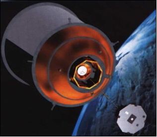
Both YES and TORI (aluminum disk) were stored in the TEAM experiment box. First YES was ejected followed shortly by TORI. In between, the tether was deployed. The TEAM box with its experiments remained attached to the Maqsat satellite.
The YES subsatellite contained also additional (secondary) experiments:
• A GPS receiver was installed to evaluate GPS reception outside the GPS constellation and to provide information on the tether dynamics and to demonstrate the use of GPS at high velocity (GTO perigee) and at high altitude (GTO apogee)
• The SF (Scintillating Fiber) detector. The SF nuclear detector module consists of three radiation measuring channels for fiber-optic-coupled SF probes. Detected radiation are fast protons and electrons. A new radiation-hardened experimental SF probe and a doped spinel crystal were flown as the third detector.
• RADFET (Radiation-sensitive Field Effect Transistor) experimentation. Three RADFETs were used to measure the total ionizing dose behind thin shielding (so-called ”skin-dose”).
• Sun senors. Seven SAS (Solar Aspect Sensors) measure the attitude of YES. Each of the seven sun sensors consists of two light-sensitive transistors mounted in an aluminium housing. On top of each transistor two baffles are mounted, forming narrow slits through which the transistor is looking out. This makes the FOV wide in one direction (about 90º) and narrow in the other (1 to 2º). As the slits on each sun sensor are perpendicular to each other, the sensors are always looking for the sun in two perpendicular planes. Together, the seven sun sensors have a 360º FOV in all three perpendicular planes through the S/C.
• Accelerometers. Test of new technologies [MNT (Micro & Nano-Technologies)] which are being considered as a possible future way to miniaturize systems and subsystems in space (measurement of vibrations). Demonstrate the LIGA/Si sensor technology for 3-axis accelerometers in space. - Two newly developed Triad 442T accelerometers were installed symmetrically with respect to the YES center of mass.
Mission Events and Results
The payload of Ariane flight 502 reached an orbit somewhat different from the nominal GTO orbit (period 7.8 hours instead of 10.7). Then, TEAMSAT was ejected from MaqSat-H without spin stabilization (as a result of safe mode), ending up in a nearly flat spin almost perpendicular to the intended direction.
The first part of the mission was reserved for the TEAMSAT experiments, depleting part of one of the large batteries inside YES via a set of banana plugs. Contact with YES was reserved for health checkouts and preliminary measurements. The communication link was limited to one satellite at a time, so there was continuous switching required between YES and TEAMSAT.
In the 9th orbit (3 days), ejection of YES was planned, with 2 TEAMSAT cameras witnessing the event. The ejection would also expose the 2 cameras on YES as well and the 2nd antennas of both TM and GPS, thus enhancing their coverage to omni-directional.
All TEAMSAT experiments so far had gone fine and were on schedule. However, during the 6th orbit, project operations was unable to switch on the YES telemetry, despite numerous trials. Later on, it was discovered that YES had already been ejected. This caused a search for YES with ground-based cameras and with the TEAMSAT cameras VTS and AVS.. Communication with YES could not be re-established. The search was ended about 96 hours after launch (4 days). The new orbit of YES was later confirmed by radar tracking and optical images taken from the ground.
Since YES has not been operated after its ejection, its mission (i.e. tether deployment) was never performed and can therefore be considered a “failure”, in contrast to the overwhelming success of the other TEAMSAT experiments.
References
1) D. A. Arnold, “The Behavior of Long Tethers in Space,” The Journal of the Astronautical Sciences, Vol. 35, No. 1, January-March 1987, pp. 3-18
2) I gratefully acknowledge the major review, revision and addition of this chapter provided by Michael Zedd of NRL, Washington, D. C.
3) R. L. Forward, J. Davis, “Doing the Do-Si-Do,” Launchspace Magazine, April/May 1998
4) M. L. Cosmo, E. C. Lorenzini (editors), “Tethers In Space Handbook,” Third Edition, Dec. 1997, NASA/MSFC, URL: http://www.tethers.com/papers/TethersInSpace.pdf
5) L. Johnson, R. D. Estes, E. Lorenzini, et al., “Electrodynamic Tethers for Space Propulsion,” Proceedings of AIAA, Reno, NV, Jan. 12-15, 1998, AIAA 98-0983
6) http://en.wikipedia.org/wiki/Tether_propulsion
7) Nestor Voronka, “Space Tethers and Small Satellites: Formation Flight and Propulsion Applications,” URL: http://mstl.atl.calpoly.edu/~workshop/archive/2007/Spring/01e-Voronka-Space%20Tethers.pdf
8) http://www.tethers.com/TethersGeneral.html
10) Joseph A. Carroll, John C. Oldson, “Tethers for Small Satellite Applications,” Proceedings of the 9th Annual AIAA/USU Conference on Small Satellites, Logan, Utah, USA, Sept. 19-22, 1995, URL: https://web.archive.org/web/20110716212510/http://www.tetherapplications.com/papers/small_satellite.pdf
11) “The OEDIPUS Tethered Sounding Rocket Missions,” Reference , pp. 28-35
12) http://www.aoe.vt.edu/~cdhall/courses/aoe4065/NASADesignSPs/TIS_chap1.pdf
13) R. Hoyt, J. Slostad, R. Twiggs, “The Multi-Application Survivability Tether (MAST) Experiment,” Proceedings of the 39th AIAA/ASME/SAE/ASEE Joint Propulsion Conference and Exhibit, July 20-23, 2003, Huntsville, AL, USA, AIAA-2003-5219, URL: http://www.tethers.com/papers/MASTJPC2003Paper.pdf
14) “The MAST Experiment: A Low-Cost Picosat Experiment to Demonstrate Space Tether Technologies,” URL: https://web.archive.org/web/20130129183724/http://www.tethers.com/Missions.html
15) M. McKee, “Inspector Gadget to star in space tether test,” New Scientist Space, March 28, 2007, URL: http://space.newscientist.com/article.ns?id=dn11466&feedId=online-news_rss20
16) The MAST Experiment Blog, http://www.tethers.com/MAST_Blog.html
17) Kelly Young, “Experimental space tether fails to deploy,” May 11, 2007, NewScientist news service, URL: http://space.newscientist.com/article/dn11836
18) J. G. Laframboise, D. D. Wallis, H. G. James, “Effects of Large-Amplitude RF Emissions on OEDIPUS-C Floating Voltages,” URL: http://dev.spis.org/projects/spine/home/tools/sctc/VIIIth/79374443c0a8001400da839ff2cd51d8?action=download&nodecorator
19) D. J. Knudson, D. D. Wallis, H. G. James, “Tethered Two-Point Observations of Solitary Auroral Density Cavities,” Geophysical Research Letters, Vol. 26, 1999
20) A. Jablonski, F. Vigneron, G. Tyc, and H. G. James, “OEDIPUS-C Mission Tether Dynamics Results,” paper presented at the Tether Technology Interchange Meeting, MSFC, Sept. 9-10, 1997, NASA/CP-1998-206900
21) J. McCoy, C. O'Neill, J. Stanley, T. Settecerri, “Plasma Motor-Generator (PMG) Flight Experiment Results,” Proceedings of the Fourth International Conference On Tethers In Space, Washington DC, April 10-14, 1995, pp. 57-82
22) “The Plasma Motor Generator (PMG),” Reference , pp. 21-24
23) L. Wilson, D. Chlouber, R. J. Jost, “Electrodynamic tether currents in the day/night ionosphere : Correlations during the Plasma Motor Generator mission,” Journal of Geophysical Research, Vol. 101, 1996, No A10, pp. 21657-21688
24) L. Johnson, J. Ballance, “Propulsive Small Expendable Deployer System (ProSEDS) Space Demonstration,” paper presented at the Tether Technology Interchange Meeting, MSFC, Sept. 9-10, 1997, NASA/CP-1998-206900
25) L. Johnson, “The Tether Solution,” IEEE Spectrum, July 2000, Vol. 37, No. 7
26) Joseph A. Carroll, “SEDS Deployer Design and Flight Performance,” AIAA Paper 93-4764, 1993, URL: https://web.archive.org/web/20110716213259/http://www.tetherapplications.com/papers/aiaa93-4764.pdf
27) F. Smith, “The First and Second Flights of the Small Expendable Deployer System (SEDS),” Proceedings of the Fourth International Conference on Tethers in Space, Washington, DC., April 10-14, 1995.
28) H. F. Smith, “The First and Second Flights of the Small Expendable Deployer System (SEDS),” Proceedings of the Fourth International Conference On Tethers In Space, Washington DC, April 10-14, 1995, pp. 43-56.
29) J. R. Glaese, “A comparison of SEDS-2 flight and dynamics simulation results,” Proceedings of the Fourth International Conference on Tethers in Space, Washington DC., April 10-14, 1995
30) Tether Physics and Survivability (TiPS) Fact Sheet, Nov. 1996, URL: http://www.nro.gov/news/press/1996/1996-08.pdf
31) W. Barnds, S. Coffey, M. Davis, et. al., “TiPS: Results of a Tethered Satellite Experiment,” paper presented at the AAS/AIAA Astrodynamics Conference in August 4-7, 1997, Sun Valley, Idaho, AAS 97-600.
32) K. T. Alfriend, W. J. Barnds, S. L. Coffey, L. M. Stuhrenberg, “Attitude and Orbit Determination of a Tethered Satellite System,” AAS/AIAA Astrodynamics Specialist Conference, Halifax, Nova Scotia, Aug. 14-17, 1995, AAS 95-351, URL: http://jungfrau.tamu.edu/html/alfriend/alfriendpublications/Tethers/JGDC_paper_.pdf
33) http://code8100.nrl.navy.mil/programs/tips.htm
34) E. M. Levin, “TiPS dynamics analysis,” Acta Astronautica, Volume 50, Issue 9, May 2002, pp. 527-534
35) J. S. G. Penson, M. Burchell, “Hypervelocity Impact Studies on Space Tethers,” Proceedings of the 54th IAC (International Astronautical Congress), Bremen, Germany, Sept. 29 to Oct. 3, 2003, IAC-03-I.5.4, URL: http://www.zarm.uni-bremen.de/iaf2003/abstracts/data/pdf/IAC-03-I.5.04.PDF
36) http://nasascience.nasa.gov/missions/tss
37) N. Stone, et al., “A Review of Scientific and Technological Results from the TSS-1R Mission,” paper presented at the Tether Technology Interchange Meeting, MSFC, Sept. 9-10, 1997, NASA/CP-1998-206900
38) B. Strim, M. Pasta, and E. Allais, “TSS-1 vs. TSS-1R,” Proceedings of the Fourth International Conference On Tethers In Space, Science and Technology, Hampton, VA, Apr. 1995, pp. 27-42
39) C. B. Smith, M. Bandecchi, S. Habenic, D. Hardy, P. Sinander, “The TEAMSAT Data Handling System,” URL: http://microsat.sm.bmstu.ru/e-library/ccdh/Common/TeamDHS.pdf
40) A. Bradford, F. Müller-Stute, B. Sarti, “Engineering TEAMSAT - From Concept to Delivery,” ESA Bulletin, No 95, Aug. 1998, URL: http://www.esa.int/esapub/bulletin/bullet95/BRADFORD.pdf
41) S. Habinc, D. Hardy, P. Sinander, C. Smith, “TEAMSAT’s Data-Handling Systems,” ESA Bulletin, No 95, August 1998, URL: http://www.esa.int/esapub/bulletin/bullet95/HABINC.pdf
42) M. Betto, J. L. Jorgensen, T. Riis, “The autonomous vision system on TeamSat,” Proceedings of the IEEE Aerospace Conference, Vol. 2, 1999, pp. 83-93, Snowmass, CO, USA, March 6-13, 1999
The information compiled and edited in this article was provided by Herbert J. Kramer from his documentation of: ”Observation of the Earth and Its Environment: Survey of Missions and Sensors” (Springer Verlag) as well as many other sources after the publication of the 4th edition in 2002. Comments and corrections to this article are always welcome for further updates (eoportal@symbios.space).