Space Fence
Space Situational Awareness
Space Fence for SSA (Space Situational Awareness) Services
Solution Program Status Capabilities and partnerships References
The SFS (Space Fence System) is a second-generation ground-based space surveillance system of S-band radars designed to greatly enhance the legacy AFSSS (Air Force Space Surveillance Network). Space Fence will provide unprecedented sensitivity, coverage and tracking accuracy, and contributes to key mission threads with the ability to detect, track and catalog small objects in LEO (Low Earth Orbit), MEO (Medium Earth Orbit) and GEO (Geostationary Earth Orbit). When operational in the next decade, the new Space Fence capabilities of the U.S. Air Force will revolutionize SSA (Space Situational Awareness) by detecting orbital hazards well in advance of an eventual collision. 1)
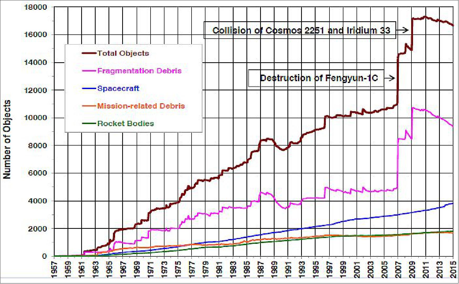
Space is no longer a vast, empty void. Unprecedented quantities of new satellites, derelict satellites, and debris litter the skies, posing an imminent threat to the space assets of all nations. Orbital debris generally refers to material that is on orbit as the result of human space activities/initiatives, but is no longer serving any function. The use of outer space presents a number of hazards to spacecraft owners and operators. Increasing use of space has brought a new source of risk collisions with manmade objects. The proliferation of debris in space generated by spacecraft and launchers has become a serious issue, in particular in the early 21st century. With each satellite launch, additional debris such as rocket bodies, bolts, or dust from solid rocket motors reaches orbit in addition to the intended payload.
Two events in particular worsened the SSA situation considerably and highlighted the need for more precise tracking of space objects:
1) The Chinese retired (non-operational) weather satellite FY-1C (Fengyun-1C) in polar orbit at an altitude of 865 km, was hit by a Chinese anti-ballistic missile test on January 11, 2007. This collision event completely destroyed the FY-1C spacecraft. The destruction created a cloud of more than 3,000 pieces (> 10 cm) of space debris, the largest debris cloud ever tracked, and much of it will remain in orbit for decades, posing a significant collision threat to other space objects in LEO. 2)
2) The February 10, 2009 collision of a functioning U.S. Iridium communications satellite (Iridium 33) and a derelict Russian Cosmos 2251 communications satellite (orbital altitude of 800 km), which added > 2000 pieces of debris into LEO.
According to the U.S. Satellite Catalog, the number of 10 cm and larger objects in Earth orbit decreased slightly in 2014, driven by the decay of light weight fragmentation debris during high solar activities. 3) 4)
• Since 2007 NASA has required frequent satellite conjunction assessments for all of its maneuverable spacecraft in LEO and GEO to avoid accidental collisions with objects tracked by the U.S. SSN (Space Surveillance Network).
• NASA also assists other U.S. government and foreign spacecraft owners with conjunction assessments and subsequent maneuvers.
• During 2014 NASA executed or assisted in the execution of 21 collision avoidance maneuvers by robotic spacecraft.
- 2 maneuvers were needed to avoid debris from Fengyun-1C
- 4 maneuvers were needed to avoid debris from the collision of Cosmos 2251 and Iridium 33
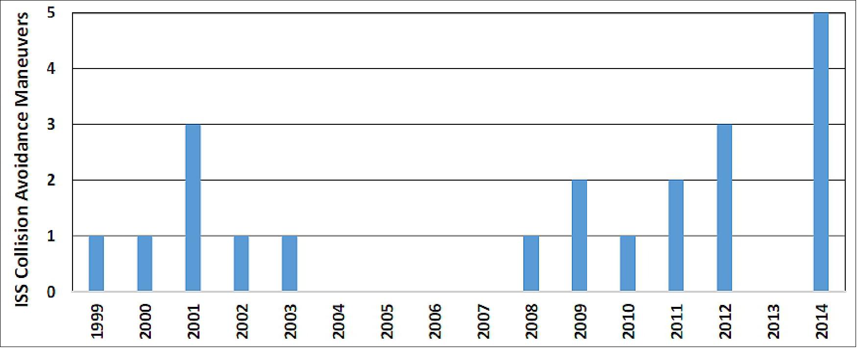
• The ISS (International Space Station) has conducted 21 debris collision avoidance maneuvers since 1999.
- During 2014, a record five debris avoidance maneuvers were executed.
Some background: SFS (Space Fence System) will enable the decommissioning of the aging U.S.-based AFSSS (Air Force Space Surveillance System), originally installed in 1961. With more than 60 nations operating in space today, the final frontier is much more complex than when the AFSSS first started tracking a few hundred orbiting objects. In the early 21st century, with hundreds of thousands of objects orbiting the Earth, space debris and risk of potential collisions now threaten national space assets providing critical services, including the Global Positioning System, banking and telecommunications.
The US Air Force Materiel Command’s Electronic Systems Center at Hanscom Air Force Base in Massachusetts leads the procurement for the USA’s Space Fence, which is intended to improve space situational awareness as legacy systems in the SSN (Space Surveillance Network) are retired. With a total anticipated value of around $6.1 billion over its lifetime, Space Fence will deliver a system of 2-3 geographically dispersed ground-based radars to provide timely assessment of space objects, events, and debris. Failure is not an option: 5)
• In 2012, Lockheed Martin is developing its technology solution for a next generation Space Fence, a program that will revamp the way the USAF (U.S. Air Force) identifies and tracks objects in space. Space Fence will use S-band ground-based radars to provide the Air Force with uncued detection, tracking and accurate measurement of space objects, primarily in low-earth orbit. The geographic separation and the higher wave frequency of the new Space Fence radars will allow for the detection of much smaller microsatellites and debris than current systems. 6) 7)
Additionally, Lockheed Martin’s Space Fence design will significantly improve the timeliness with which operators can detect space events which could present potential threats to GPS satellites or the ISS (International Space Station). 8)
Utilizing powerful, new ground-based radars, Space Fence will enhance the way the U.S. detects, tracks, measures and catalogs orbiting objects and space debris with improved accuracy, better timeliness and increased surveillance coverage. Lockheed Martin’s prototype radar recently met a key contract requirement during a series of demonstration events by proving it could detect these resident space objects, as they are referred to by the Air Force.
• In Feb. 2012, the Air Force granted its final approval of Lockheed Martin’s preliminary design for the system. Space Fence will replace the existing AFSSS (Air Force Space Surveillance System), or VHF (Very High Frequency) Fence, which has been in service since the early 1960s. The new system’s initial operational capability is scheduled for 2018.
With more than 400 operational S-band arrays deployed worldwide, Lockheed Martin is the prime contractor in S-band radar development, production, operation and sustainment. The Lockheed Martin-led team, which includes General Dynamics, AT&T and AMEC, has decades of collective experience in space-related programs including sensors, mission-processing, cataloging, orbital mechanics, net-centric communications and facilities.
• In June 2014, the Lockheed Martin industry team was awarded the contract by the USAF for the EMDPD (Engineering, Manufacturing, Development, Production and Deployment) of the Space Fence System ($915 million). The objective is to monitor hundreds of thousands of objects in orbit, allowing the military to detect and track ten times more space junk than possible with existing decades-old technology. 9)
The military's JSpOC (Joint Space Operations Center) is in charge of tracking space traffic and issuing collision threat notices to global satellite operators, which can move their spacecraft out of the way if notified in time.
The deal with Lockheed Martin Mission Systems and Training covers the construction of an S-band Space Fence radar facility at Kwajalein Atoll in the Marshall Islands, plus an option for another radar site in Western Australia. Completion of the Kwajalein radar site is scheduled for 2018.
• August 2015: The U.S. budget for SSA efforts averages about $1.0 billion per year for fiscal years 2015 through 2020. 11)
Space Fence Solution
To ensure safety of satellites in orbit it is essential to know their precise orbits as well as the orbits of debris that could cause damage. This information is also essential for the U.S. to maintain a SSA (Space Situation Awareness) capability to protect its space assets from potential hostile actions. The U.S. Air Force is developing the Space Fence System as part of its SSN (Space Surveillance Network) to provide unprecedented detection sensitivity, coverage and tracking accuracy. The Space Fence Program was initiated by the Air Force in 2005 to develop a system of geographically dispersed S-band phased array radars which provide 24/7 uncued capability to find, fix, and track small objects in LEO (Low Earth Orbit). The system was to replace (and greatly enhance the capability of) the now decommissioned very-high frequency VHF Air Force Space Surveillance System (AFSSS). The Air Force engaged industry with risk reduction contracts in 2006. The SDR (System Design Review) Concept Development Phase contracts were awarded to 3 industry teams in June 2009 and the PDR (Preliminary Design Review) Phase contracts were awarded to two industry teams in January 2011. In June 2014, the Lockheed Martin industry team was awarded the contract for the EMDPD (Engineering, Manufacturing, Development, Production and Deployment) of the Space Fence System (Ref.1).
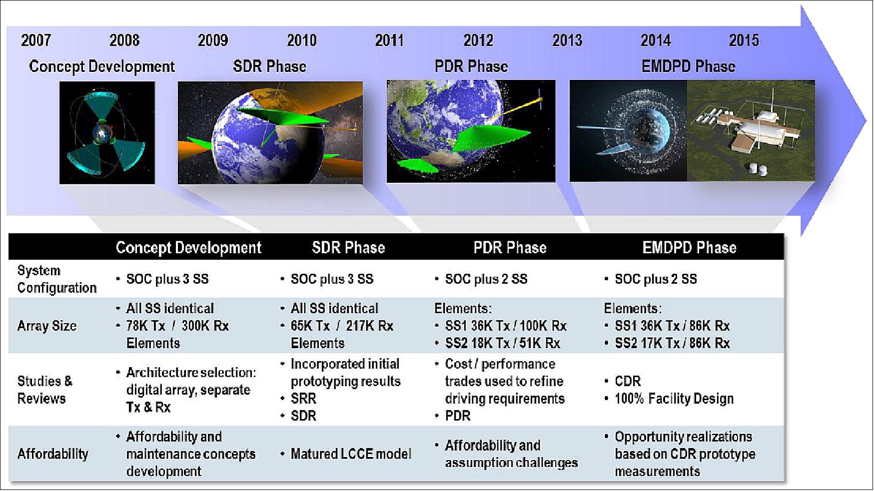
Lockheed Martin’s Space Fence System solution is a result of extensive trade studies throughout the Risk Reduction, SDR Phase, PDR Phase and current EMDPD Phase, as summarized in Figure 5. Initially, during the concept development efforts (Risk Reduction contract and self-funded studies), the requirements called for three identical SS (Sensor Sites) to be geographically dispersed around the globe and controlled by the SOC (Space Fence Operation Center). Array size at each site was driven by uncued MEO (Medium Earth Orbit) coverage and coverage was defined by fixed angular extents (e.g., ±60º for LEO and for ±30º MEO).
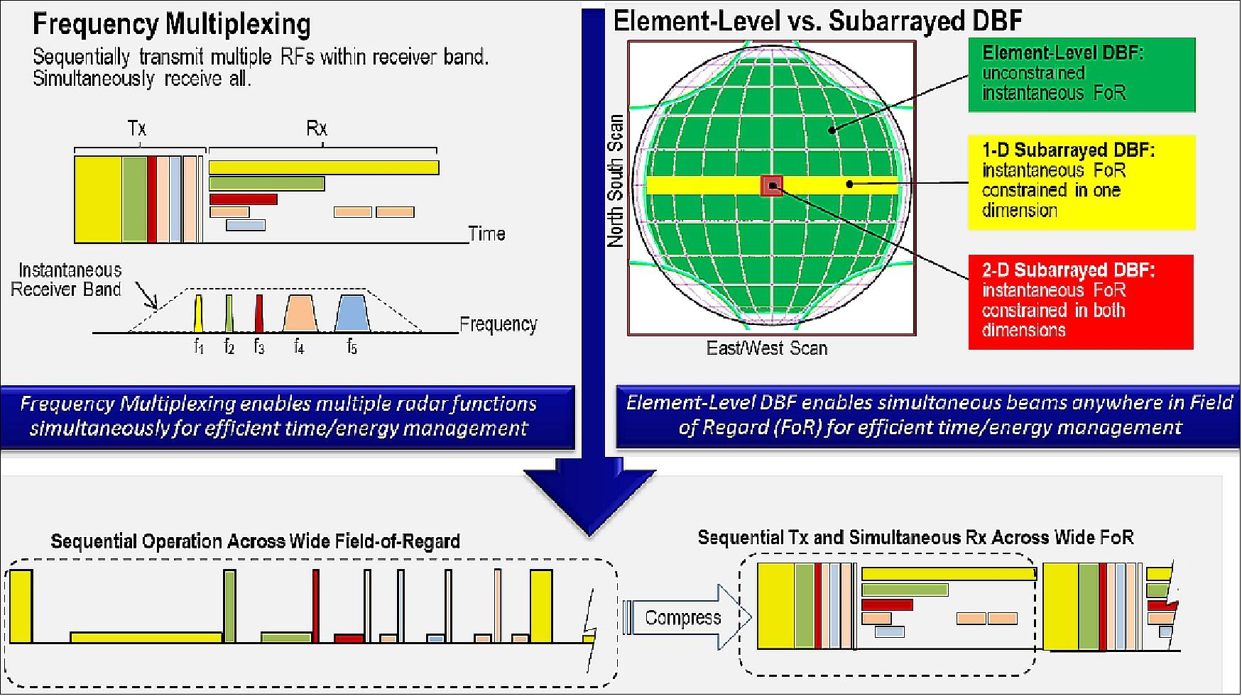
Since array size is directly proportional to cost, our solution attempted to minimize it through use of digital array technology and separate Transmit (Tx) and Receive (Rx) phased arrays. Digital arrays, particularly those that use element-level digital beamforming, are capable of many independent beams to support simultaneous functions, reducing required array size relative to doing the functions sequentially. These functions are performed simultaneously at different frequencies within the operating band ( Figure 6). Use of separate Tx and Rx arrays minimizes losses during transmit and receive, which also reduces the required size. The solution also employed GaN (Gallium Nitride) high power amplifier technology for use in the Tx array to provide high power, long pulses needed for long range operations, and high efficiency for low operating costs. Even with these key affordability trades considered, the requirements still drove the Tx array sizes excessively large (78 K radiating elements and Rx array size to 300 K radiating elements, about three times as large as the final SS).
Throughout the SDR Phase, detailed hardware prototyping of our array technology building blocks refined the performance and cost models. This led to a downsizing of our arrays to 65 K Tx and 217 K Rx elements for affordability. As the project effort entered the PDR phase, cost models were used by the USAF to adjust requirements and remove drivers such as the continuous MEO mission sensitivity over such a large uncued volume. Updated requirements focused on uncued LEO as the driver for radar sensitivity, with MEO as a tasked function that did not drive larger array sizes. This simplification and additional detailed performance modeling allowed further reduction of array sizes.
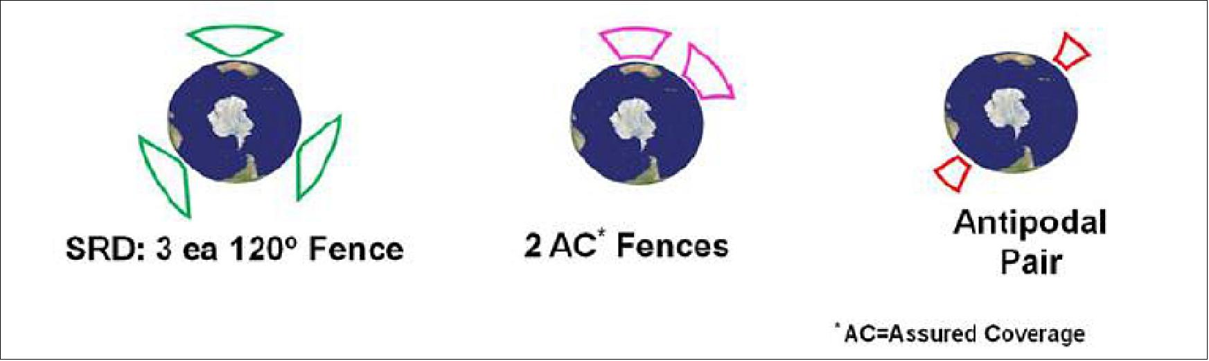
The new requirements also reduced the number of sensor sites to 2 and adjusted the coverage to optimized contours to provide 'assured coverage', as shown in Figure 7. Assured coverage provides optimized fence angular width as a function of altitude to guarantee one detection opportunity per pass (where the fence intersects the orbital plane) for circular orbits. Assured Coverage contours were also traded off with sensor site locations (Kwajalein Atoll and Australia, vs. antipodal sites such as Kwajalein and Ascension Island). 12)
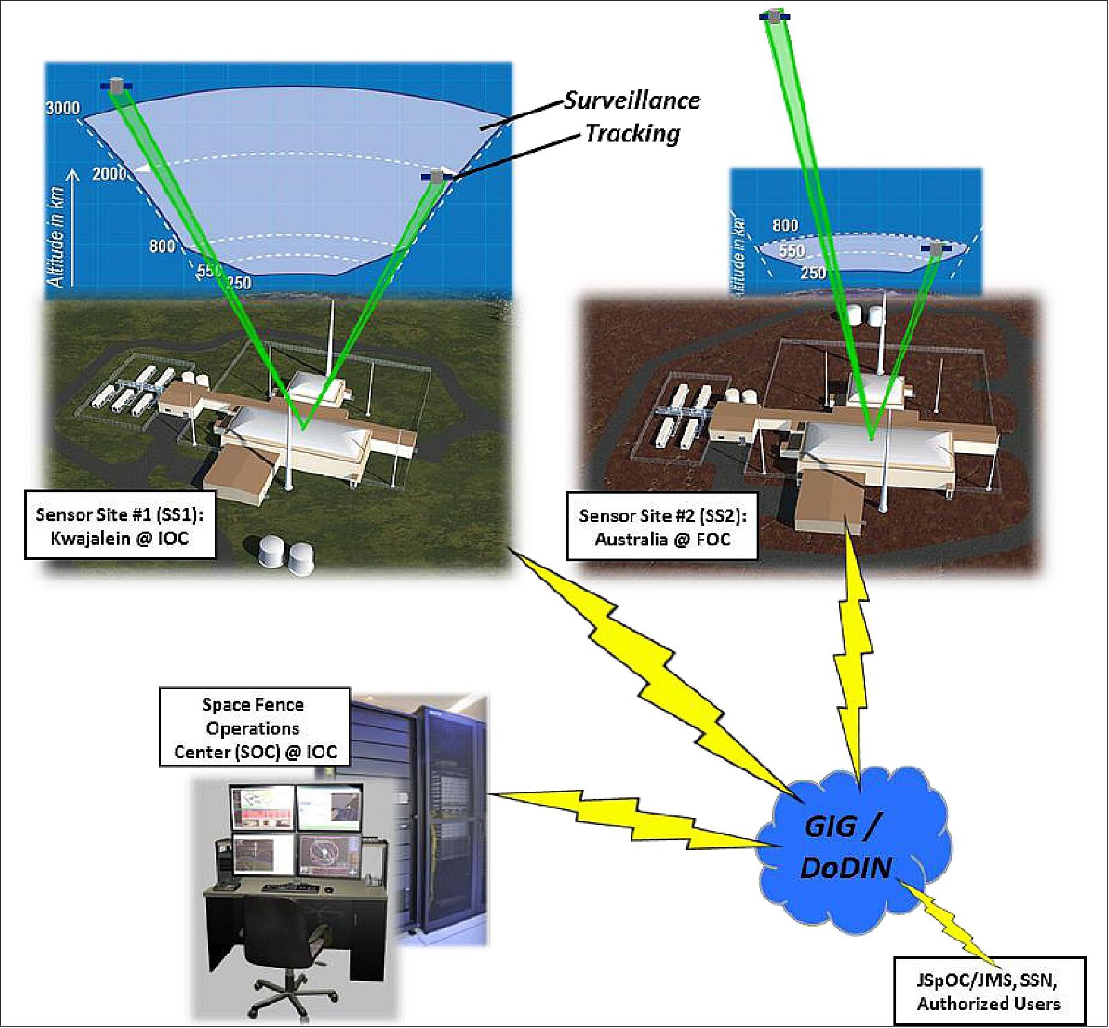
Detailed prototyping continued throughout the PDR phase into the EMDPD phase and refined performance and cost models. Based on these prototyping efforts, the final design at CDR ( Critical Design Review) incorporated numerous opportunity realizations focused on affordability and producibility. The final Space Fence design includes two minimally-manned radar sites with complementary coverage and the Space Fence Operations Center (Figure 8).
• Sept. 28, 2015: Lockheed Martin's Space Fence System, including the large-scale digital radar and turn-key facility, passed the CDR (Critical Design Review) conducted by the U.S. Air Force. Government representatives met with Lockheed Martin engineers in Moorestown, NJ (New Jersey), to review the Space Fence S-band radar system design, which will detect, track, and catalog orbital objects in space more than 1.5 million times a day to predict and prevent space-based collisions. - The completion of the CDR marks the end of the design phase and the start of radar production and facility construction of the Space Fence system. 13)
Each radar site features closely-spaced, but separate, Transmit and Receive Arrays that are mission-optimized for high availability and low lifetime support costs, including prime power. Coverage is optimized to provide assured coverage at IOC (Initial Operational Capability) down to 800 km altitude with the Kwajalein Atoll site and improved lower altitude assured coverage to 550 km at FOC (Full Operational Capability) with the addition of the Australian site. Both sites support cued tasking support to all altitudes including GEO. The Space Fence System is net-centric (interconnected by the Global Information Grid, more recently referred to as the DoDIN (Department of Defense Information Network) and will seamlessly integrate into the existing SSN, providing services to external users—such as the JSpOC (Joint Space Operations Center) — and coordinating handoffs to other SSN sites (Ref. 1).
Space Fence uses advanced S-band DBF (Digital Beamforming) radars to provide unprecedented SSA (Space Situational Awareness) services.
• Ground-based system of S-Band radars that greatly enhance the USAF Space Surveillance Network
• Consists of two minimally manned radar sites and the Space Fence Operations Center
• Detects, tracks, catalogs objects in LEO (Low Earth Orbit)
• Also provides significant capability in MEO (Medium Earth Orbit) and in GEO (Geosynchronous Orbit).
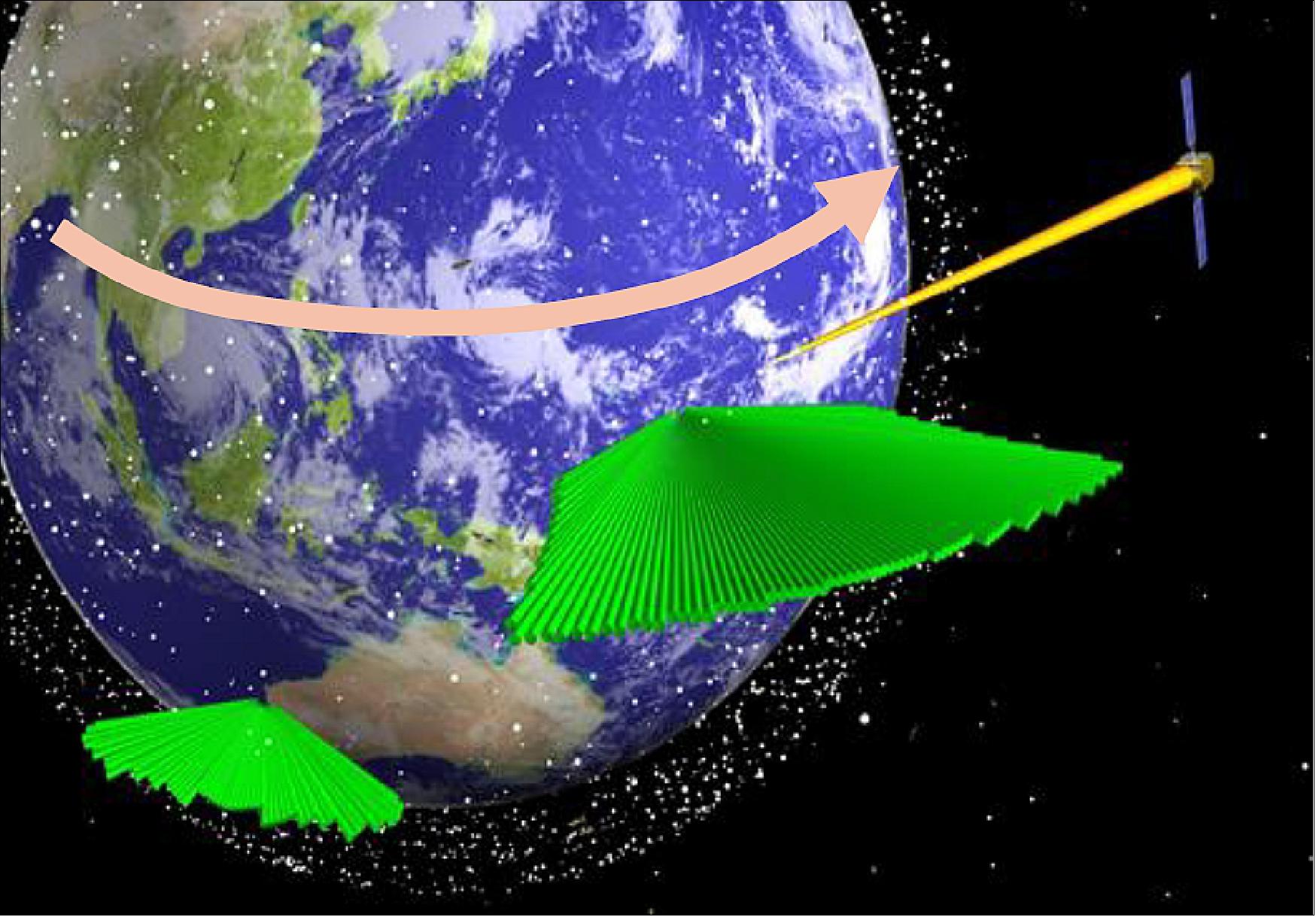
Because the SFS uses element level digital beam forming for both transmit and receive, the radar is capable of performing both un-cued surveillance and cued tracking simultaneously. Figure 9 depicts the radar at Sensor Site 1 tracking a satellite while maintaining the surveillance fence. The figure also includes the proposed Sensor Site 2 in Australia, which would be part of the LEO assured coverage mission. The Australian site would provide important surveillance over the lower sector of LEO, with additional capability to track into GEO. The two assets combined would nearly double the amount of tracks per day.
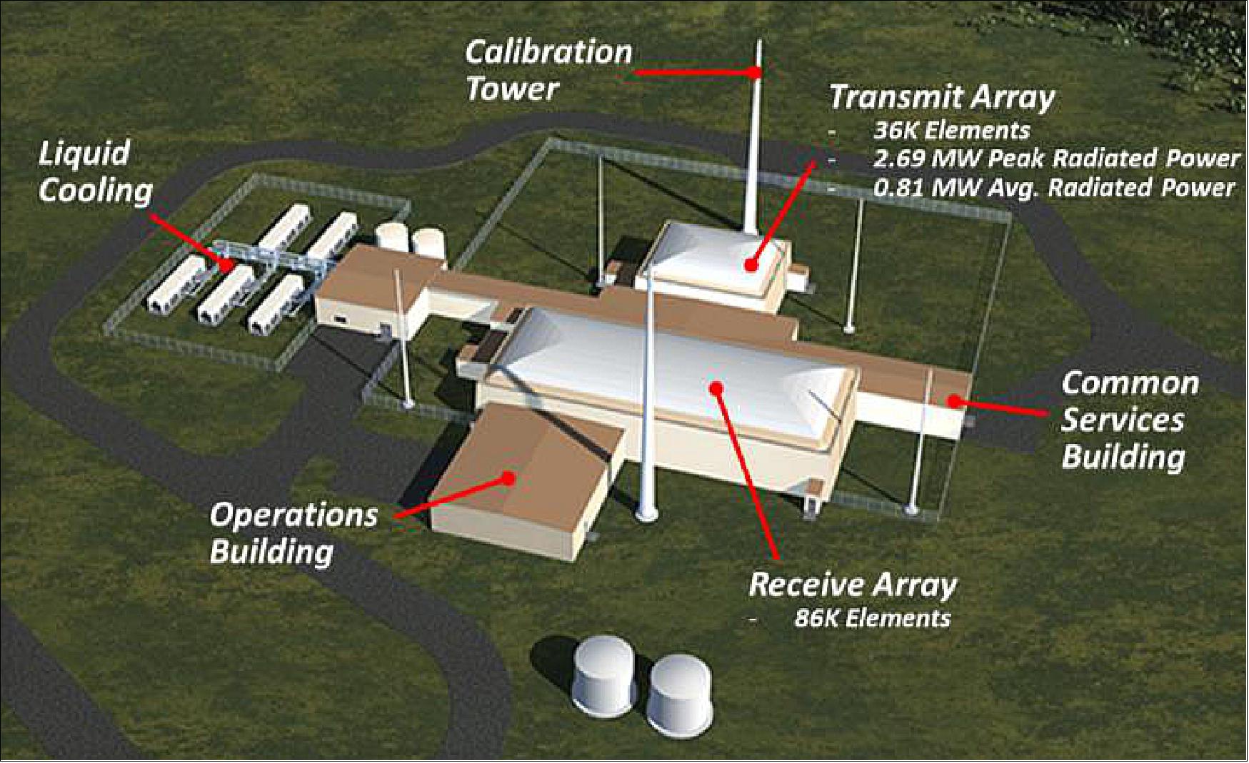
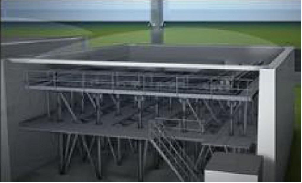
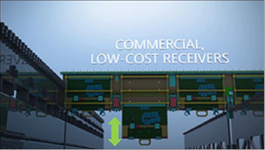
The layout of a sensor site is depicted in Figure 10. The radar architecture incorporates GaN and element-level DBF (Digital Beam Forming). These capabilities permit tremendous user-defined flexibility to customize volume surveillance and track sectors instantaneously without impacting routine surveillance functions. Arrays are built with scalable building block sections and LRUs (Line Replaceable Units) as shown in Figure 11 and Figure 12. Each array looks through a very low loss electronically transparent facility Kevlar radome that is air supported. Array electronics can be serviced from beneath while arrays are operational, permitting high system availability. Liquid cooling enables high performance and reliability. Radar control, signal and data processing, and mission processing are hosted on COTS (Commercial Off-the-Shelf) processing within the operations building.
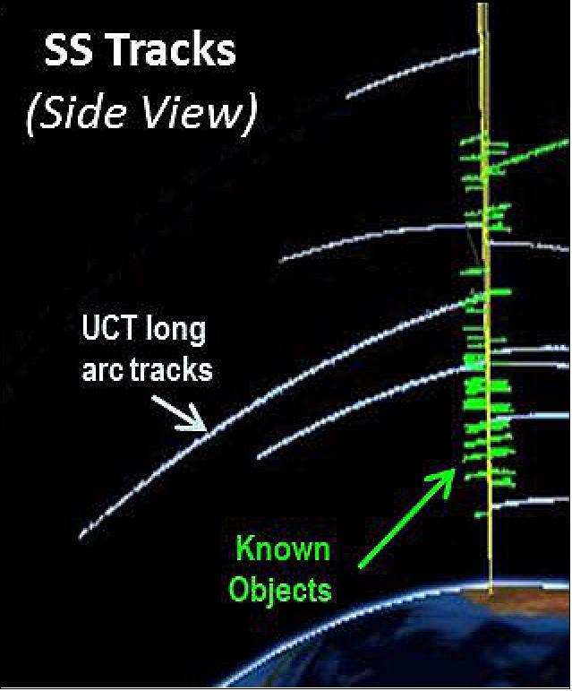
Use of element-level DBF allows the Space Fence to maintain persistent surveillance while performing tracks on hundreds of simultaneous objects detected in the fence (Figure 13). The system automatically manages resources by performing long-arc tracks on UCTs (Uncorrelated Targets) to support accurate initial orbit determination. For high-interest objects, a “micro fence” can be electronically constructed to gather more track data, focusing radar resources specifically on that object, providing more timely and accurate information, as depicted in Figure 14. Use of element-level DBF allows the Space Fence to support these cued tasks without interrupting uncued surveillance. System resource control automatically adjusts the number of beams and range extents to cover the required volume of the micro fence.
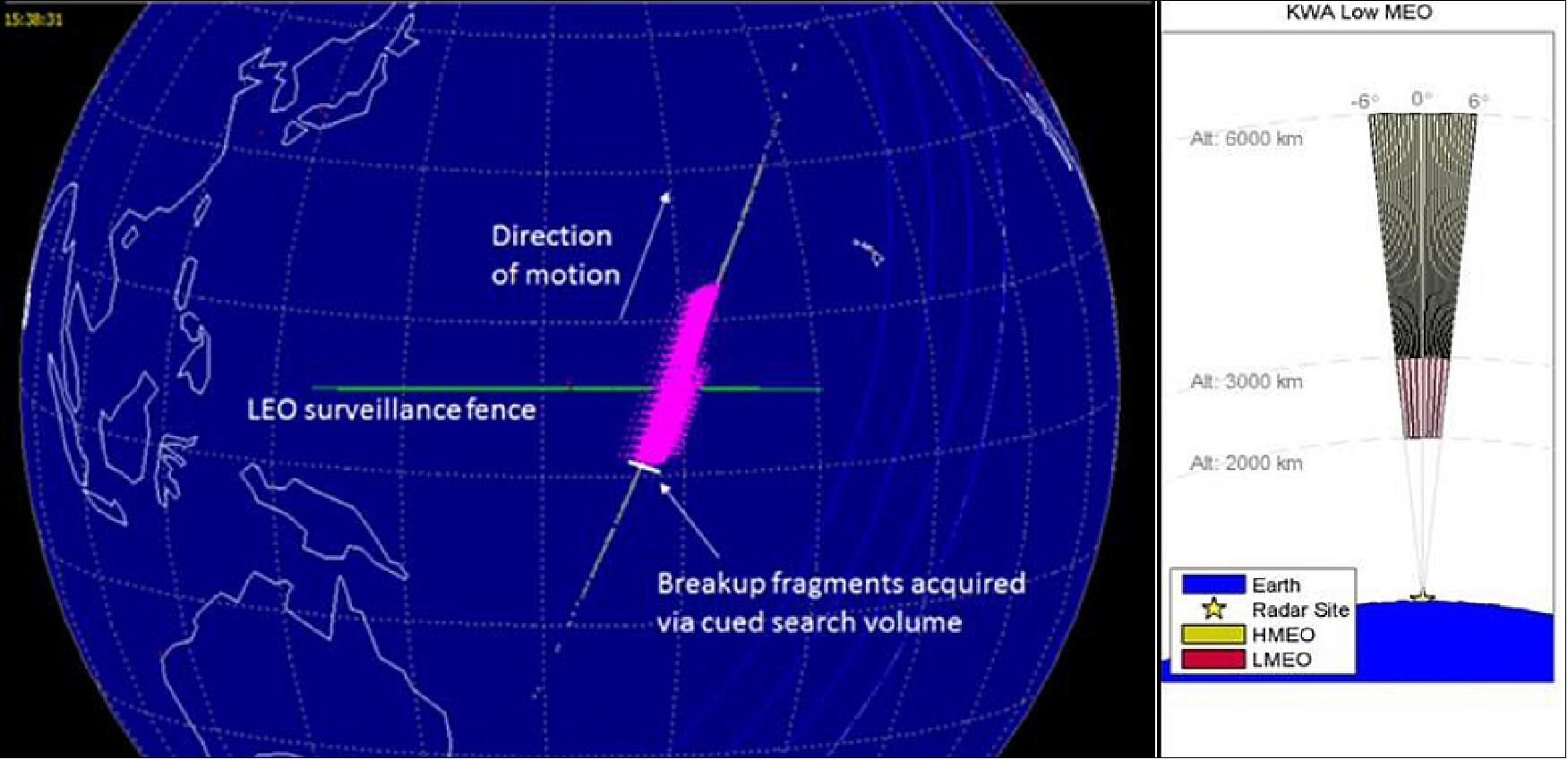
Space Fence is being developed with significant flexible coverage capabilities. For events and objects where orbit information is known, the micro fence capability can be used to put up a persistent volume without impact LEO performance. An example from high fidelity modeling and simulation is shown in Figure 14, a micro fence was used to keep a persistent volume along the ephemeris of a suspected breakup. Nearly 1000 new objects were detected and tracked as the micro fence and resources are automatically adjusted by the system to provide contiguous coverage of the suspected breakup. Micro fences can be erected anywhere in LEO, MEO or GEO coverage. When little is known about the objects of interest, another method of flexible coverage is to reallocate the uncued surveillance resources to another altitude regime such as MEO or GEO. Figure 14 also illustrates an example of uncued MEO surveillance; sized for a particular target size (available coverage will depend upon resources needed to detect the sensitivity of the objects of interest). Note during the M&S scenario for this flexible coverage case, the larger ‘future’ LEO catalog was still maintained automatically by the sensor site using micro fences and less than 1/3 of the radar resources.
Program Status
- March 30, 2020: United States Space Force officials formally declared initial operational capability and operational acceptance of the Space Fence radar system, located on Kwajalein Island in the Republic of the Marshall Islands, on March 27, 2020. 14)
- Space Fence provides significantly improved space surveillance capabilities to detect and track orbiting objects such as commercial and military satellites, depleted rocket boosters and space debris in low, medium, and geosynchronous Earth orbit regimes.
- Before Space Fence, the Space Surveillance Network (SSN) tracked more than 26,000 objects. With the initial operational capability and operational acceptance of Space Fence, the catalog size is expected to increase significantly over time. Information about objects tracked by the SSN is placed in the space catalog on https://www.space-track.org/auth/login.
- The Space Fence Program Office (AFLCMC/HBQB) operating under the acquisition authority of the Space and Missile System Center awarded a contract to the Lockheed Martin in June of 2014 to develop Space Fence. This system is the most sensitive search radar in the SSN, capable of detecting objects in orbit as small as a marble in low earth orbit (LEO).
- Space Fence is operated by the 20th Space Control Squadron (SPCS), Detachment 4, at the Space Fence Operations Center in Huntsville, Alabama, and provides data to the 18 SPCS located at Vandenberg Air Force Base, California. The 18 SPCS uses the data from Space Fence and other sensors within the SSN to maintain the space object catalog and screen operational satellites, both maneuverable and non-maneuverable, against all objects in the space catalog, which includes satellites, rocket bodies and debris.
- Space Fence provides precise positional data for Space Domain Awareness to maintain a robust and accurate space object catalog, ensure orbital safety, and provide early warning for conjunction events and indications of potential threats.
- Both the 18th SPCS and 20th SPCS are part of the 21st Space Wing, headquartered at Peterson Air Force Base in Colorado Springs, Colorado. The 21st SW is the Department of the Air Force’s only wing providing ground-based missile warning, missile defense and space surveillance data in defense of North America and its allies.
- General Jay Raymond, Chief of Space Operations, USSF (United States Space Force ) and Commander, U.S. Space Command, said Space Fence is revolutionizing the way space is viewed by providing timely, precise orbital data on objects that threaten both manned and unmanned military and commercial space assets. These space capabilities are critical to the national defense and way of life, which is why Space Fence is so important to enhance the ability to identify, characterize and track threats to those systems.
• December 10, 2019: When the U.S. Air Force declares operational acceptance of the Space Fence radar located on Kwajalein Atoll, it will play a critical role in providing a tactical advantage to our warfighters in the space domain. Space Fence will utilize its flexibility, coverage, and sensitivity to detect and accurately track significantly more objects than the current-day catalog. This crucial capability is now one step closer to providing unprecedented space situational awareness with the system completing its developmental and operational testing phases and has entered a trial period - one of the last steps before achieving operational acceptance. 15)
- Beyond cataloging objects, Space Fence will detect closely-spaced objects, breakups, maneuvers, launches and conjunction assessments from LEO through GEO. Frequent collisions and deterioration of assets, such as defunct satellites and rocket boosters, have increased the amount of space debris and raised the risk of future collisions in space. According to NASA's most recent Orbital Debris Quarterly News, NASA calculates about 17.6 million pounds of objects are in Earth orbit. That number will only grow as more commercial space projects launch massive constellations with thousands of small satellites, presenting a huge problem for both U.S. government and commercial organizations.
- That’s where the U.S. Air Force’s Space Fence will play a crucial role.
- The radar system will also play a crucial role in the everyday lives of Americans, as we become more dependent on spaceborne technologies for everything from weather forecasting, banking, global communications to GPS navigation. Today, these critical services are being threatened by hundreds of thousands of objects and space debris orbiting the Earth.
- “Space Fence will revolutionize the way we track and classify objects that threaten both manned and unmanned military and commercial space assets critical to our national defense and economy,” said Dr. Rob Smith, vice president and general manager of Lockheed Martin’s Radar and Sensor Systems. “The Air Force Space Surveillance Network currently tracks about 25,000 objects. When Space Fence comes online, the catalog will experience significant growth and when fully operational, Space Fence will be the world’s largest and most advanced radar system, providing unprecedented space situational awareness.”
- Space Fence has already begun to prove its unmatched capabilities. During testing of the system in March, it detected the debris field from an anti-satellite test conducted by India. Space Fence observed a significant amount of debris tracks surrounding the time of the event, and the system proved its ability to automatically predict and correlate their next crossing times.
- In a 2019 interview with Breaking Defense, Gen. John Hyten, U.S Strategic Command commander said of the Space Fence radar system, “I’ve been out there and the data is eye watering. It’s better than we even thought it would be.”
- Once the Trial Period is successfully completed, operational acceptance of the radar will be declared by the Air Force.
- Space Fence uses advanced solid-state S-band radar technology. The technology includes element level digital beamforming, Gallium Nitride-based, software defined programmability that can be adapted over time to address emerging needs of the warfighter.
- Air Force Space Command’s Space and Missile Systems Center, located at Los Angeles Air Force Base in El Segundo, California, is the U.S. Air Force’s Center of Excellence for acquiring and developing military space systems. Its portfolio includes the Global Positioning System, military satellite communications, defense meteorological satellites, space launch, range systems, satellite control networks, spaceborne infrared systems and space situational awareness capabilities.
• September 26, 2019: U.S. Strategic Command (USSTRATCOM) expanded the space situational awareness (SSA) program to academic institutions by signing the first such agreement with California Polytechnic (Cal Poly) State University. 16)
- Rear Adm. Richard Correll, director of plans and policy for USSTRATCOM, and Jeff Armstrong, president of Cal Poly, signed the agreement joining over 100 commercial and foreign nations working together to expand situational awareness within the space domain.
- “Academic partnerships such as these provide a foundation for research in space,” said Correll. “Improving SSA, through technical advancements and increased sharing, grows our collective ability to avoid collisions by rapidly detecting, warning, characterizing and attributing natural or man-made phenomena affecting space systems and the space environment.”
- Cal Poly already works closely with Vandenberg Air Force Base, California, providing data to support space flight safety for their CubeSats.
- “Cal Poly is honored to be the first academic institution to enter into an official partnership with U.S. Strategic Command,” said Armstrong. “This first-of-its-kind partnership will allow current and future Cal Poly students to gain hands-on experience working with our four CubeSats currently on orbit and how they affect, and are affected by, other satellites on orbit. These invaluable experiences will prepare our graduates for successful careers in the space and technology industries.”
- Cal Poly joins 20 nations — Australia, Japan, Italy, Canada, France, South Korea, the United Kingdom, Germany, Israel, Spain, the United Arab Emirates, Belgium, Norway, Denmark, Brazil, the Netherlands, Thailand, New Zealand, Poland and Romania; two intergovernmental organizations — the European Space Agency and the European Organization for the Exploitation of Meteorological Satellites; and more than 80 commercial satellite owner/operator/launchers already participating in SSA data-sharing agreements with USSTRATCOM.
- “Universities play a vital role in the exploration and understanding of space,” Correll said. “The future of space is reliant on research and the advancement of technology to enhance overall space-flight safety and the long-term sustainability, stability, safety, and security of the space environment.”
- SSA data-sharing agreements enhance multinational space cooperation and streamline the process for United States’ partners to request specific information gathered by Air Force Space Command’s 18th Space Control Squadron at Vandenberg AFB. The information is crucial for launch support, satellite maneuver planning, support for on-orbit anomalies, electromagnetic interference reporting and investigation, satellite decommissioning activities and on-orbit conjunction assessments. With the establishment of the 11th combatant command, future SSA agreements will be signed and facilitated by U.S. Space Command.
- USSTRATCOM has global responsibilities assigned through the Unified Command Plan that include strategic deterrence, nuclear operations, joint electromagnetic spectrum operations, global strike, missile defense, and analysis and targeting.
• June 21, 2019: The US Air Force (USAF) is cooling on funding and procuring the second Space Fence space situational awareness (SSA) site because the program's mission changed from space traffic management to detecting attacks and transitioned from a military to civilian need, according to a former USAF and Pentagon official. 17)
- Douglas Loverro, former deputy assistant secretary of defence and former USAF Space and Missile Systems Center (SMC) director, told Jane's on 21 June that the big need when the program was founded in 2007 was space traffic management - tracking the 20,000 objects, mostly in low Earth orbit (LEO), and ensuring objects did not collide with each other. The legacy Air Force Space Surveillance System (AFSSS), he said, was not able to track very small objects reliably enough.
- Loverro said by the time prime contractor Lockheed Martin was awarded a contract in 2014 to procure the first Space Fence site, the Pentagon's view of space traffic shifted from avoiding collisions to detecting attacks. The commercial space industry, he said, was also on the cusp of large growth in small satellites, which caused the Pentagon to realize that this was going to become a civil problem of space congestion, not a military problem.
- "Our mission is not really to go and do civil traffic management and traffic cop in space," Loverro said. "Our mission is to do defence against attacks. While Space Fence is a great system ... attacks in low Earth orbit do not require two space fences; they only require one."
- The USAF awarded Lockheed Martin a USD914.6 million contract in 2014 for Space Fence, a phased-array, gallium nitride (GaN)- powered S-band radar that can provide constant coverage for anything in LEO, which is 3,000 km and below.
• May 22, 2019: The U.S. Air Force Space Fence system detected the breakup field from an anti-satellite test conducted by India during a scheduled endurance exercise of the new space surveillance radar. 18)
- As MICROSAT-R was expected to pass through the un-cued surveillance fence, Space Fence automatically issued a "breakup alert" indicating there were multiple objects within close proximity. Space Fence observed a significant amount of debris tracks surrounding the time of the event crossing labeled as uncorrelated targets. Long-arc tracking was initiated within the orbital debris cloud to form accurate initial orbit determinations. With this information, the system was able to automatically predict and correlate the next crossing time.
- Lockheed Martin system operators then prepared for the next crossing by setting up an enhanced sensitivity task volume ahead of the normal un-cued surveillance fence to increase the low altitude track duration. Although the Space Fence is currently in its test phase and not yet operational, the Space Fence un-cued surveillance coverage showed its unique ability to observe these events unfolding at different altitudes in real time. Although the anti-satellite test was conducted at approximately 300 km, the debris cloud extended beyond the original parent object orbit.
- "Although the Space Fence system is still under test, it continues to demonstrate its advanced capabilities providing operationally-relevant information in all orbital regimes from Low Earth Orbit through Geosynchronous Earth Orbit," said Dr. Rob Smith, vice president and general manager of Radar and Sensor Systems for Lockheed Martin. "The criticality of space assets to both national defense and the world economy cannot be understated. As multiple new mega constellations consisting of thousands of satellites become a reality and the space domain continues to become more congested, the demand for more accurate and timely space situational awareness data will be of the utmost importance to the warfighter."
- The Space Fence system continues to track objects from the anti-satellite event through the government-led testing phase which began in early April.
- Colonel Stephen Purdy, Director of the Space Superiority Systems Directorate, Space and Missile Systems Center, Los Angeles Air Force Base, who oversees the Space Fence program said, "Space Fence is already proving itself as a capable system even before becoming operational. The Indian test showcased Space Fence's capabilities in a real-world event. The system was able to quickly respond to a highly dynamic situation providing critical data. Space Fence is the latest in a long line of capabilities we are collectively bringing to the warfighter as we continue to build out space capabilities for the United States."
• May 3, 2018: In June, Lockheed Martin plans to complete integration of the U.S. Air Force Space Fence on Kwajalein Atoll in the Marshall Islands and begin tracking objects, at least in a testing mode. 19)
- Full integration and testing is scheduled to begin in July as the company confirms the S-band radar array meets all contractual requirements. “After that, we will turn it over to the Air Force for testing and trials,” said Bruce Schafhauser, Lockheed Martin Space Fence program manager.
- As companies prepare to send hundreds or thousands of satellites into communications constellations in low Earth orbit, government agencies and commercial satellite operators are calling for enhanced space situational awareness and space traffic management.
- The Air Force Space Fence in Kwajalein will help but Lockheed Martin is hoping to provide additional observations with a second Space Fence in Western Australia. The Air Force authorized Lockheed Martin to begin surveying the site for the second radar facility but has not yet allocated funding to build it.
- “Having a second space fence will give you more opportunities to track and ultimately understand where things are so you can help prevent collisions,” said Matthew Hughes, business development manager for Lockheed Martin space surveillance programs.
- In early 2019, the Kwajalein Space Fence is scheduled to begin initial operations. The Space Fence will sends out a curtain of radio frequency energy wider than the continental United States. As satellites and debris pass through the curtain, the system will detect them and determine whether the objects are already in the Space Surveillance Network’s catalog, Schafhauser said.
- “If they correlate with what’s in the catalog, we drop them pretty fast,” said Schafhauser. “But if it’s something new, we track it through the entire field of regard and get a very accurate orbital determination.”
- In addition to keeping tabs on low Earth orbit, the Space Fence is designed to create smaller “micro-fences” in every orbit up to geostationary orbit,” Schafhauser said.
• November 15, 2016: Air Force, Army and industry leaders came together during a ribbon cutting ceremony at the new Air Force Space Fence Operations Center located at the ROC-H (Reagan Test Site Operations Center-Huntsville) facility in Huntsville,AL, Nov. 15. 20)
- The Space Fence will use S-band ground-based radars to provide the Air Force with detection, tracking and accurate measurement of space objects in orbit. The locations and higher wave frequency of the new Space Fence radars will permit the detection of much smaller microsatellites and debris than current systems. The new system's initial operational capability is scheduled for 2018.
• November 5, 2016: The program is on-track to 2018 IOC (Initial Operational Capability). 21)
- Extensive modeling, simulation and prototyping completed
- User evaluation periods have optimized operator controls and interfaces
- System design is focused on automating operator functions and reducing operator workload
- Space Fence will provide unprecedented capability for SSA (Space Situational Awareness).
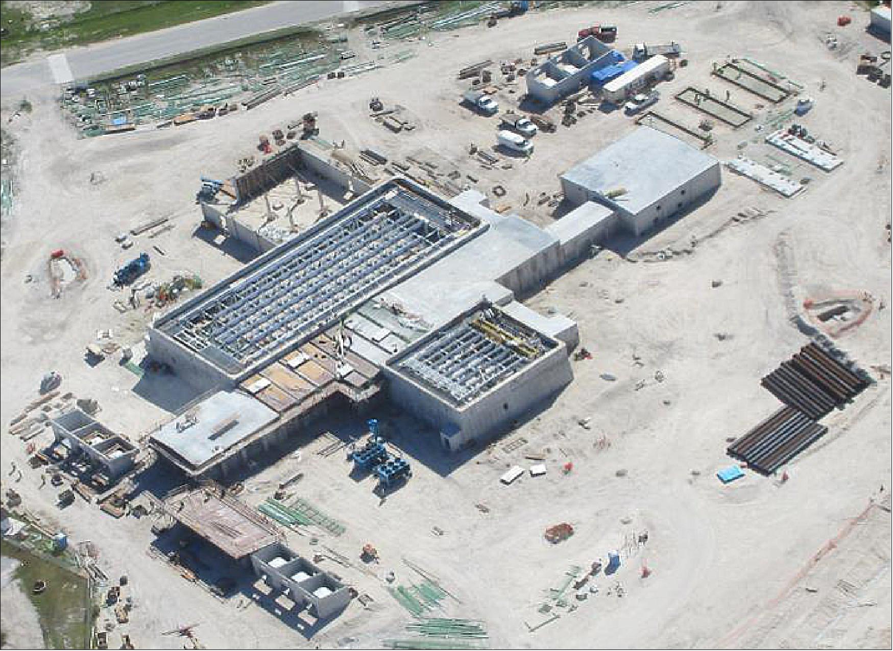
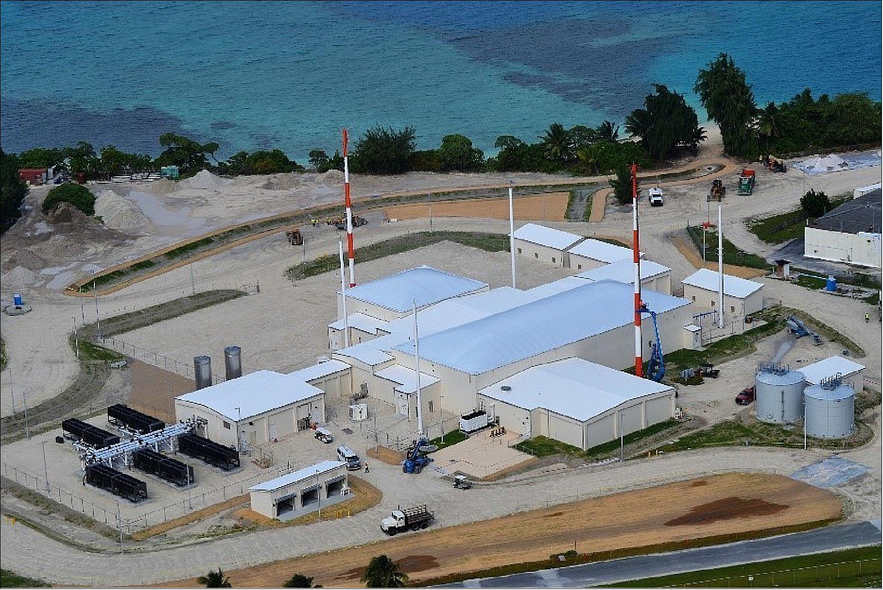
• September 2016: The Radar transmit and receive building construction for sensor site #1 (Kwajalein Atoll) is nearing completion while the SOC continues to make steady progress toward readiness for equipment installation later in 2016. The Space Fence Program is on-track for IOC (Initial Operational Capability) in 2018. The Australian sensor site (site #2) FOC (Full Operational Capability) is planned for 2021. 22)
• April 7, 2016: General Dynamics SATCOM Technologies completed the construction and walk-through of the 650 m2 radar receive array structure that is part of the U.S. Air Force Space Fence radar system. With the array structure complete, the General Dynamics Space Fence team will carefully dismantle the 317 ton steel structure and ship it to Kwajalein Atoll, Marshall Islands, for reassembly and integration into the Space Fence system. Officials from the Air Force Space Fence program office and representatives from General Dynamics SATCOM Technologies and Lockheed Martin, the prime contractor for the Space Fence program, participated in the walk-through. The structure was built at General Dynamics’ Wortham, Texas, precision manufacturing facility. 23)
- The structure stands 12 meters tall and is about the size of two regulation NBA basketball courts placed side-by-side. It is designed to withstand earthquakes, hurricane force winds and extremes in temperature and humidity while maintaining a consistent surface flatness that varies less than one millimeter from one end of the structure to the other and from side-to-side. To prepare for the journey to Kwajalein, workers at the Wortham facility will map the structure in meticulous detail, down to the location of each individual bolt. The components will then be carefully wrapped and arranged so the reconstructed array will be identical to the structure completed in Wortham.
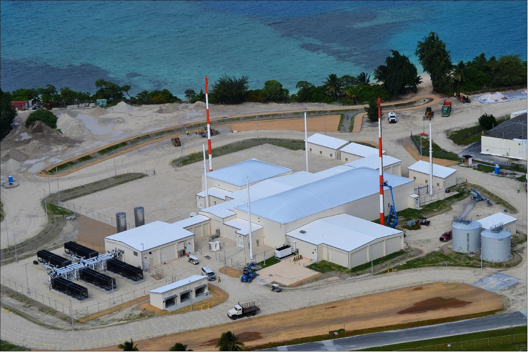
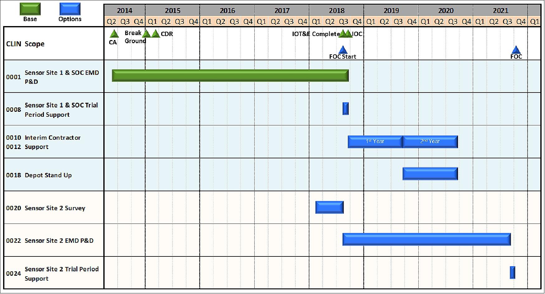
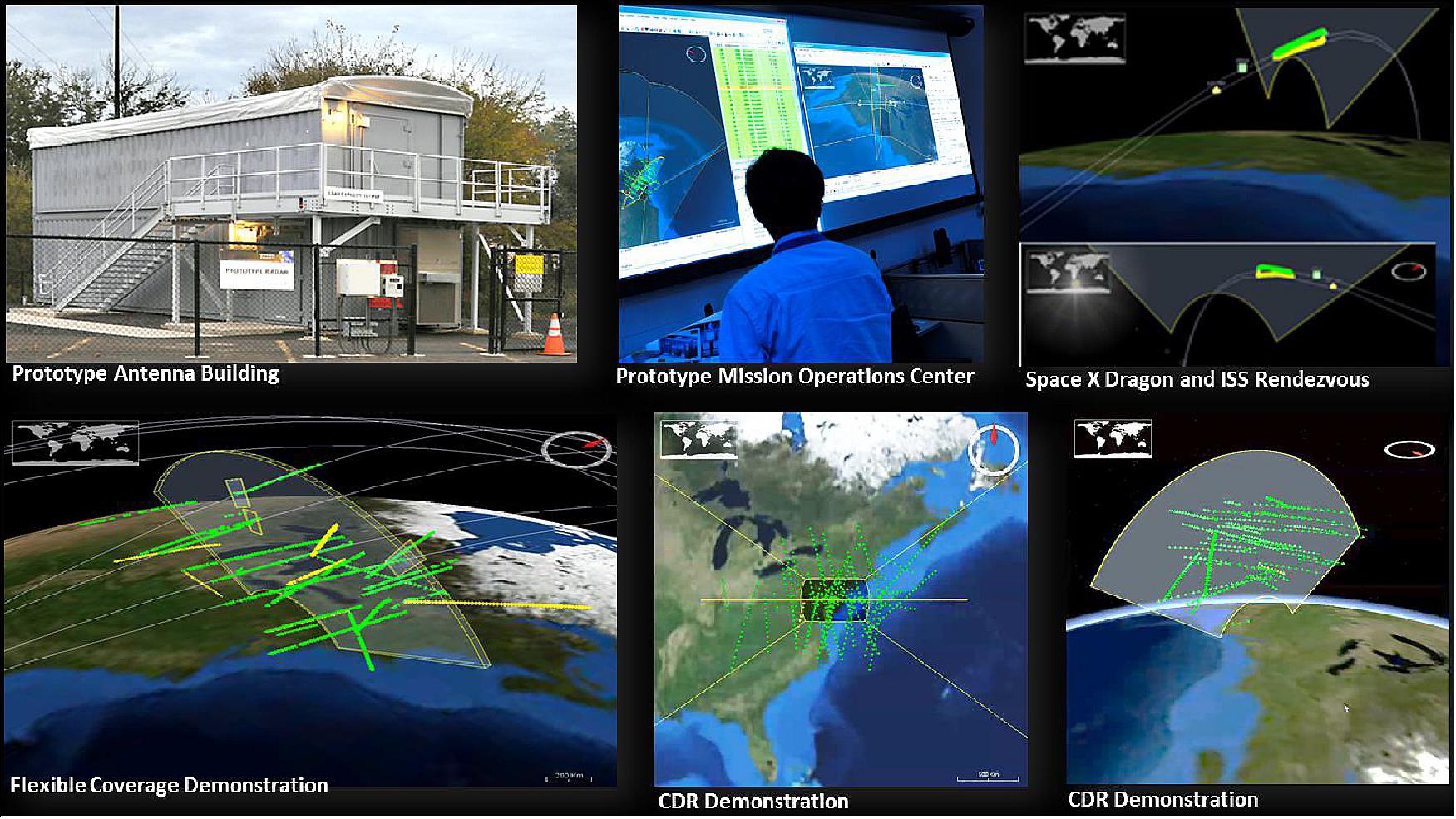
• The overall program schedule is depicted in Figure 19. In October 2015, the CDR (Critical Design Review) and 100% Facility Design Review were successfully completed. These events not only reviewed the design, but also assessed the TRL (Technology Readiness Level ) as level 7 and the MRL (Manufacturing Readiness Level) as level 7. During the CDR event an extensive end-to-end prototype demonstration of the system was successfully conducted (Figure 20). This prototype has been previously described as part of a multi-sensor (radar, laser, telescope) net-centric test bed. Ground breaking for sensor site 1 took place on Kwajalein Atoll in February 2015, as illustrated in Figure 22. The sensor site consists of the radar as well as a power plant annex to bolster the generation capabilities of Kwajalein. The Space Fence Program is on-track for IOC (Initial Operational Capability) in 2018. The second sensor site is planned for 2021 (Ref. 1).
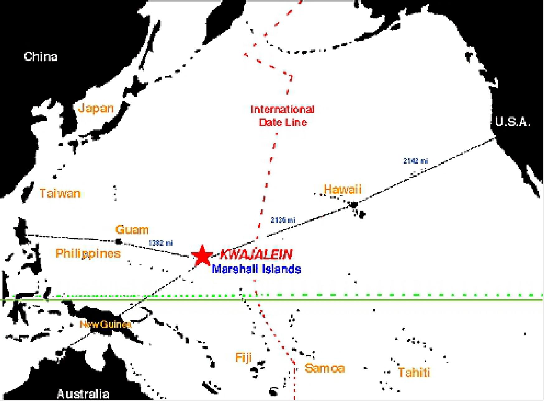

Legend to Figure 22: In a special February 2015 ceremony on Kwajalein Atoll in the Pacific Ocean – more than 2,100 nautical miles (3400 km) southwest of Honolulu – the U.S. Air Force and Lockheed Martin broke ground at the future six-acre site of the new Space Fence radar system. The event marks the official start of construction for the S-band ground-based radar system, designed to replace the 1960s AFSSS (Air Force Space Surveillance System) to improve the way objects are tracked in orbit and increase our ability to predict and prevent space-based collisions. 24)
Radar Model in a NASA 2030 Catalog Environment
Lockheed Martin’s high fidelity model of the SFS (Space Fence System) is actively used for capability analysis. The model runs using Mission and Radar control software used in the actual system, executing functions to point beams, analyze returns, determine orbits, and report observation data. Therefore, the model functions as a very accurate representation of the actual system. A modeling and simulation scenario is run by populating the simulated environment with orbiting objects both cataloged and uncataloged, then executing the simulated SFS with both a surveillance fence and optional taskings reporting on detections, observations and tracks as the operational system would. 25)
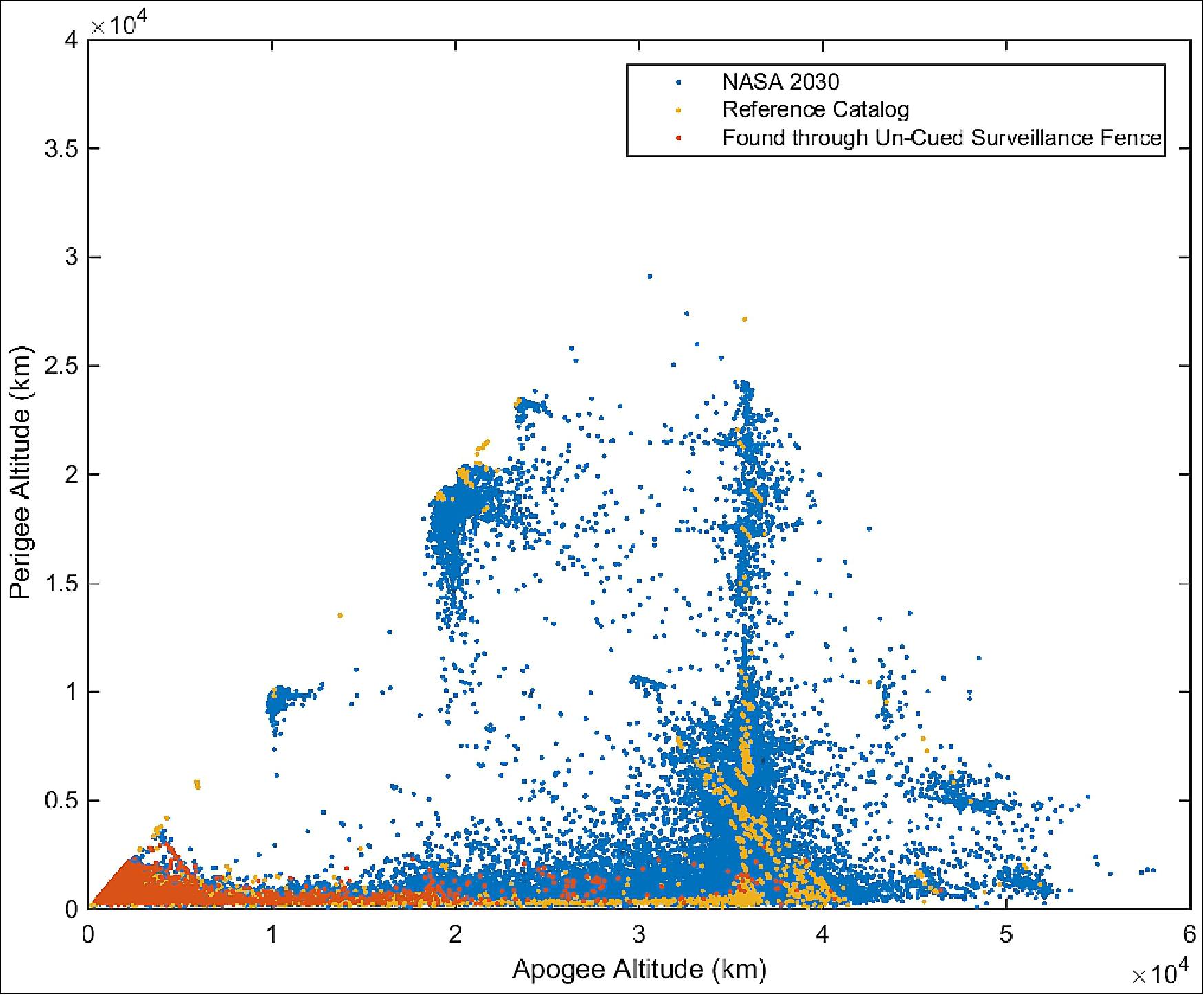
For this study, the model was run using an environment based on the NASA 2030 Simulated Catalog, which is an estimate of the future space environment consisting of over 150,000 objects of differing sizes down to 1cm and in a wide variety of orbits. The catalog was created in 2006 using two high-fidelity models, LEGEND (the NASA long-term orbital debris projection model) and NaKModule (the NASA sodium potassium droplet deposit model) . 26) The simulation environment lasted five days, where Space Fence Sensor Site 1 in Kwajalein was able to track the majority of the 14,011 objects in its reference catalog (a simulation of the current day NORAD two-line element set catalog) and discover 51,227 objects which were seen at least two times and correctly correlated between those passes. Thus, the radar maintained a steady state catalog of 65,238 objects over the course of the five days.
The Kwajalein radar’s LEO fence was modeled for the entirety of the simulation, detecting objects with an altitude below 3000 km. Figure 23 shows the apogee and perigee of objects the radar discovered and maintained of the modified NASA 2030 catalog. Notice all objects found by the SFS had a perigee whose altitude was within the fence. Also, note that the simulation only reported objects it could see; there were many instances where objects’ orbits did not pass through the fence. The majority of the objects in the reference catalog were in LEO, with a sampling through MEO (Medium Earth Orbit), HEO (Highly Elliptical Orbit), and GEO.
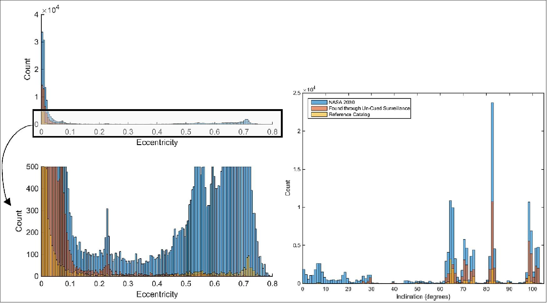
The simulation showed Space Fence’s ability to collect observations on elliptical and high inclination objects. Figure 24 shows how the radar expanded the catalog with trends similar to those in the modified NASA 2030 catalog. The radar’s un-cued fence is able to detect mainly semi-circular orbits. Due to typical inclinations of highly elliptical orbits, the object is unlikely to pass through the fence even though its altitude is within the fence’s detectable range. However, these objects could be tasked for tracks beyond the fence as the object moves towards or away from perigee. The figure also shows few objects were found at very low inclination, because the radar is geographically located at 9 degrees North latitude and the objects never passed through the fence. The radar did find many objects in typical LEO orbits with inclinations ranging from 60º to 110º.
Conjunction Assessment of Expanded Catalog
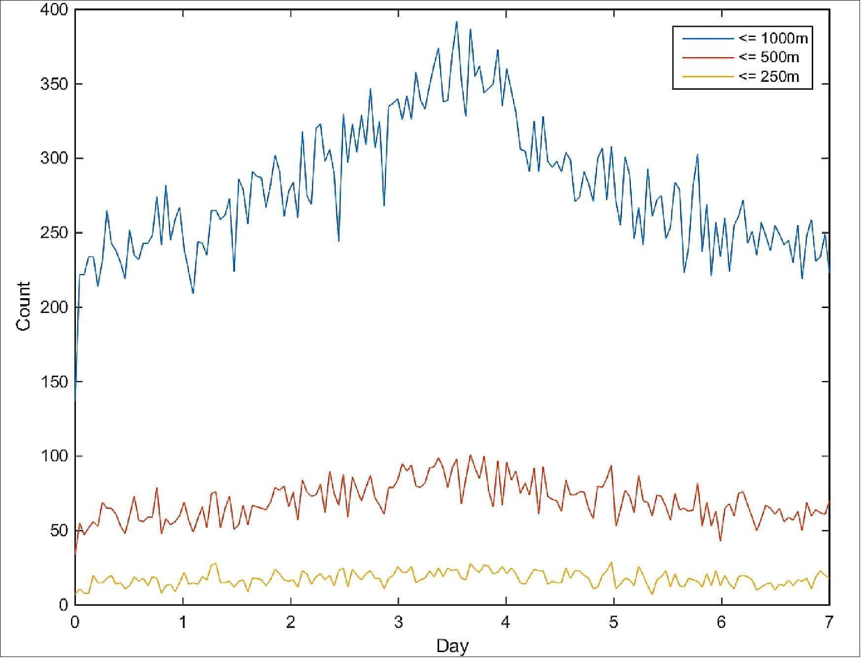
Conjunction assessment was conducted on a representative internal SFS catalog in steady state. Roughly 65,000 objects were analyzed using COMBO V5.4.2, the “Computation Of Miss Between Orbits” module in the Astrodynamic Standards Software suite. The program performed All-Versus-All CA over a 7 day period, calculating the time, distance, and relative speed of closest approach. The count of closest approaches showed a linear relationship with closest approach distance (Ref. 26), shown in Figure 25.
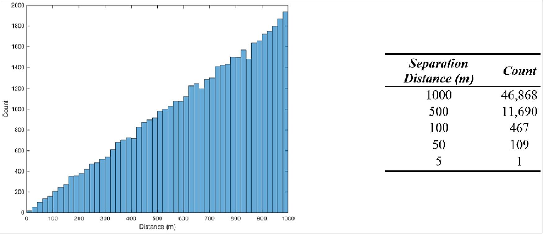
There were 46,868 occurrences when the objects came within 1 km of each other. The closest two objects came was within 5 meters in that simulated week. While the objects were modeled as discrete points, many would be roughly ten centimeters in diameter or larger. This could mean that debris-causing events, whose debris cloud would be in Space Fence’s view, may occur weekly. While these events are unfortunate, Space Fence would aid in the scientific analysis and model development of impacts by collecting observations of the debris cloud multiple times per day. In these instances, the radar operator could create a micro fence in the path of the debris cloud to find the new objects including those much smaller than the un-cued fence would naturally detect.
As seen in Figure 26 , there will be a periodicity associated with conjunctions, not a steady amount per day. Debris fields like those caused by the Iridium and Cosmos collision or the Chinese anti-satellite test would require more taskings if an object were to pass through the cloud. While many of the close approaches/collisions would not be between operational satellites, a plethora of objects flagged for close passes could be tracked to create a database of object interactions. This dataset could be used for probability of collision analysis and refinement. The radar scheduler can handle tens of thousands of taskings per day without interrupting LEO surveillance, thus the entirety of the objects with a possible conjunction under 1 km could be tasked to the radar to collect additional passes and observations.
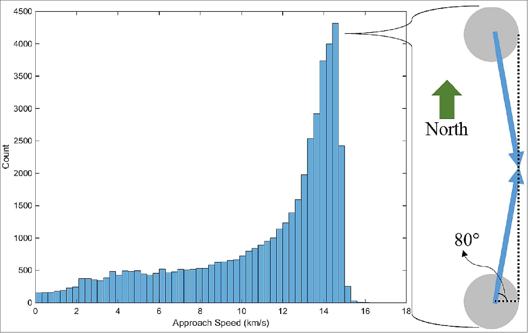
The impact speeds are shown in Figure 27, where the count increases exponentially with speed. Notice the peak at 14 km/s. This derives from objects in high inclinations impacting each other moving in opposite directions; this instance is visualized in the figure where the conjunction was flattened into a plane. The majority of the objects found by Space Fence in the simulation existed in LEO where orbit speeds are around 7 km/s and many of the objects’ inclinations were 80º. At such a high inclination, the objects’ north-south speed is roughly 98.5% of its total speed. Thus, two objects approaching each other with the majority of their speed in antiparallel directions would collide at 14 km/s as seen in the histogram.
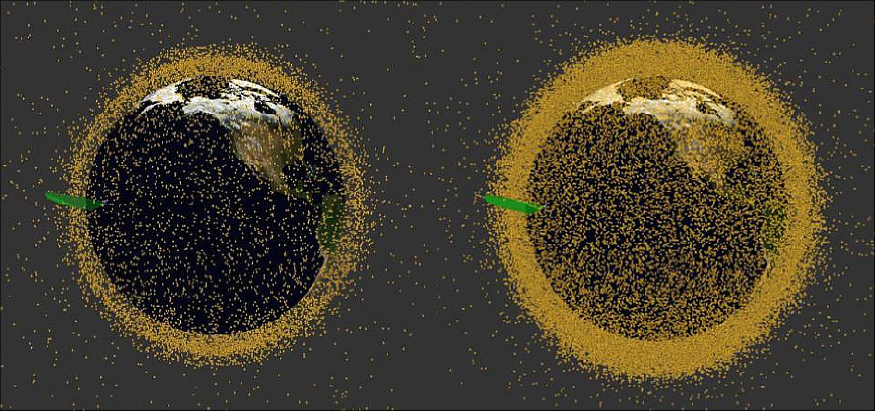
CA (Conjunction Assessment) of Expanded Catalog on NASA Satellites
There is a concern that when Space Fence becomes operational, current analysis tools and scripts will be overburdened by the massive increase in cataloged objects. This catalog increase is visualized in Figure 28. To understand the extent of the impact, a set of roughly sixty TLEs (Two-Line Elements) was analyzed for conjunctions against both a catalog of recently (within 30 days) updated RSOs (Resident Space Objects) from 13 July, 2016 and the expanded catalog of well-maintained objects from the simulation. The TLEs were representative of satellites actively monitored for conjunctions by NASA, which included all orbit regimes: LEO, MEO, HEO, and GEO. The catalog contained 10,626 objects whose TLEs epoch were sufficiently current for COMBO to analyze. Over a seven day period, there were 17 close approaches where two objects passed within 1 km of each other. These instances would be flagged by JSpOC and a notification would be sent to NASA for further analysis on the probability of collision between the debris and their satellites of interest. Compare this to the scenario where the NASA representative catalog was run against the expanded catalog. Over a seven day period, there were 48 conjunctions when objects came within at 1 km of each other. On average, it could be expected that seven instances per day satellites would be in danger of a collision and would require intensive probability of collision calculations conducted long beforehand. This is nearly a 300% increase in workload once the catalog expands.
Status Quo of Existing SSA Capabilities and Partnerships
In the timeframe of the early 21st century, all spacecraft operators experience the orbital congestion of operational spacecraft and debris, in particular in the LEO, GEO and MEO regions. SSA (Space Situational Awareness) is a global phenomenon,it is defined as the comprehensive knowledge of the population of space objects, of the space environment, and is critical to protecting space assets and providing assured space services — military, civil, and commercial.
The main implementing bodies of SSA activities are the USAF (U.S. Air Force), and NASA in the U.S. and the EC (European Commission) and ESA (European Space Agency) in Europe. In the U.S., USAF is the entity that operates and maintains SSA assets, while the Secretary of Defence and the Director of National Intelligence are responsible for policy and international cooperation on SSA, as well as for cooperating with the industry. The SSN (Space Surveillance Network) of NORAD, a bi-national U.S. and Canadian organization, is a key asset in the field of SSA, providing for a comprehensive space surveillance capability. Russia also has operational space surveillance capabilities and maintains a regularly updated space object catalog. SSA activities are becoming more important in terms of a comprehensive security and safety policy related to space. Spaceborne systems, such as navigation, Earth observation and communication satellites have become indispensable to the good functioning of economic and government structures. Any loss of services from these systems would have a serious impact on a wide range of commercial, civil and military activities (Ref. 41).
As more countries, companies and organizations field space capabilities and benefit from the use of space systems, it is in the collective interest of the space community to act responsibly, promote transparency and enhance the long-term sustainability, stability, safety and security of space.
A certain infrastructure is required by all participants in the SSA partnership club to share (receive/transmit and process) SSA warning functions and to be able to plan eventual evasion maneuvers in case of a collision thread.
• The U.S. Air Force has the best set of SSA capabilities, although not ideal: 27)
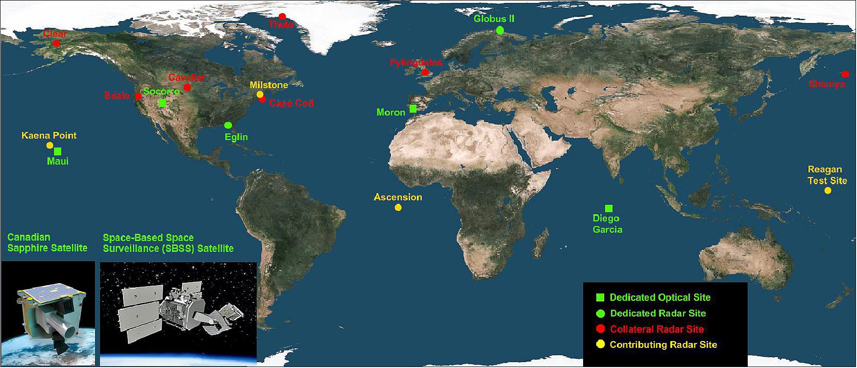
- USAF operates a global network of 30+ ground based radars and optical telescopes, plus 2 satellites in orbit, SBSS (Space-Based Space Surveillance) and Sapphire of Canada. The SBSS-1 pathfinder spacecraft was launched on September 26, 2010; The Sapphire minisatellite was launched on Feb. 25, 2013.
- Maintains the most complete tracking database of 23,000+ space objects bigger than 10 cm
- Data fed to JSpOC (Joint Space Operations Center) in California
- Provides a range of data and services for US government, satellite operators, and public.
• Limitations of the current U.S. SSA capabilities:
- Outdated hardware and software
- Very little coverage in the Southern Hemisphere or Asia, Africa, and South America.
• In 2014, the U.S. is in the middle of a significant shift in policy on its approach to space security:
- Old: unilateral approach with U.S. buying/operating a full spectrum of capabilities and giving allies access (politically-driven partnerships)
- New: cooperative approach with U.S. focusing on core capabilities and getting rest from allies/commercial industry (capability-driven partnerships).
- Between April and August 2014, JSpOC transitioned from CSM (Conjunction Summary Messages) to the standardized format CDM (Conjunction Data Message), defined by the CCSDS (Consultative Committee for Space Data Systems). 28) 29)
• Drivers of this fundamental shift:
- Declining defense budgets and fiscal pressure
- Inability to protect traditional space architecture against threats
- Increased focus on national security uses of space by other countries
- Commoditization of technology leading to explosion of private sector incentives, interest, and innovation.
- Each country will operate their own national space operations center
- Some level of communication/coordination between the national centers is needed.
• In September 2014, at a meeting in Ottawa, Canada, officials of the U.S. Strategic Command (Stratcom, also called USSTRATCOM) signed a MOU (Memorandum of Understanding) with three allied nations (Australia, Canada and the United Kingdom) on CSpO (Combined Space Operations) to strengthen deterrence, enhance resilience and optimize resources. The initiative will give participating nations an understanding of the current and future space environment, an awareness of space capability to support global operations and military-to-military relationships to address challenges and ensure the peaceful use of space, DoD officials said. 30) 31)
- Focus areas for combined space operations include space situational awareness, force support, launch and reentry assessment and contingency operations.
- Coalitions and partnerships represent a necessary step within national security that increases transparency, strengthens deterrence, improves mission assurance, enhances resilience and optimizes resources across participating nations.
• In all, the U.S. government has signed nearly 50 data-sharing agreements with other governments and private-sector entities, Defense Department officials said in September 2015. The United States has signed similar agreements with the United Kingdom, Canada, Australia, Italy, Japan, France, and Korea. The two international organizations are ESA and EUMETSAT. Germany joined the SSA club in January 2015. 32)
A number of counties and organizations are in the process of installing their own ground-based/or and spaceborne assets to contribute to the overall SSA scenario.
• The U.S. Strategic Command and ESA (European Space Agency) will share SSA (Space Situational Awareness) data, the organizations announced Oct. 30, 2014. The move continues a U.S. effort to bolster the number of countries and organizations, Strategic Command shares data with as the space environment becomes more congested. The more timely and customizable data exchange enabled by this agreement will improve our measures for collision avoidance as well as the safety of satellites immediately after launch in their early operations phase. The U.S. SSN (Space Surveillance Network) of ground- and space-based assets tracks the paths of debris large enough to be in its catalog and warns operators of possible future collisions so that the active satellites can be maneuvered out of the way. 33)
• One of the goals of ESA's SSA Program for SST (Space Surveillance and Tracking) is the successful establishment of expert centers for supporting optical and laser observations. These centers will serve as the focal point for interfacing with segment-external sensors and assets, provide feedback on the data and will be able to request and manage observations. 34)
- In April 2014, the European Commission established the European SST framework, to promote the use of national assets and processing capabilities of Members States. Those national capabilities have to guarantee an initial European architecture to provide SST services with the huge challenge of gradually becoming self-sufficient and independent in producing an integrated European space surveillance network.
- The national contribution to the European architecture will be composed of both radars and optical sensors, since they have different capability and provide a complementary type of information regarding targeted objects. Collected data from networked sensors will be sent to a national integration center in order to analyze it and make the orbit determination of the detected space debris using specific software tools.
- ESA's SSA program was authorized at the November 2008 Ministerial Council and formally launched on January 1, 2009. The mandate was extended at the 2012 Ministerial Council until 2019, and the program is funded through to 2016. 35)
- In July 2013, ESA’s existing PROBA-2 solar observatory satellite was shifted to the responsibility of the SSA program, becoming in effect ESA's first ‘SSA mission’.
- New SSA coordination centers for space weather (at Space Pole, Brussels) and for NEOs (at ESA/ESRIN) are being inaugurated, and these will start providing precursor services on a test and evaluation basis. A Tasking Center has been established at ESA/ESOC, and will begin providing a trial realtime response capability.
- European cooperation: A crucial aspect of SSA activities is cooperation. SSA is managed directly by ESA on behalf of the Agency’s Member States, who fund the program. SSA also includes cooperation with European national and regional authorities, including ministries of defense, national space agencies and national research establishments, particularly those with existing ground- and space-based sensors.
• Italian Air Force (ITAF) recognizes the relevance of a sensor architecture for a SST (Space Surveillance and Tracking) capability to protect its own space and satellite assets and infrastructure against the damage or destruction from collision with other space debris in orbit. In 2011, the Italian Government has delegated the ITAF, with collaboration of ASI (Italian Space Agency) and INAF (National Institute for Astrophysics), to study the feasibility of a national architecture using already existent assets and processing capabilities for SST. It was started a survey at national level and an experimentation using radar sensors, property of ITAF and INAF, both in monostatic and bistatic configuration. 36)
• April 16, 2015: The U.S. Strategic Command and the French Ministry of Defense have expanded their SSA (Space Situational Awareness) data-sharing agreement to include classified information, the countries announced April 16 at the 31st Space Symposium in Colorado Springs, CO. 37)
- The United States and France were already sharing unclassified SSA data under an agreement signed in January 2014. That agreement allowed Stratcom to provide data from the Joint Space Operations Center at Vandenberg Air Force Base, California, directly to the French military upon request. Previously, such requests had to be approved at higher levels of the U.S. government. This new agreement will allow the countries to share “advanced SSA” data and classified data when appropriate.
• Canada is very active in contributing to the SSA cause. On May 4, 2012, the Canadian Armed Forces (CAF) signed a Memorandum of Understanding with the U.S. Air Force, starting the SSA partnership with JSpOC to reduce the risk of loss of critical space capabilities, such as telecommunications, weather satellites, earth observation satellites, and GPS. Space is an integral part of Canadian society and economy, it is essential for the functioning of all key sectors, e.g. financial, power, agriculture, telecommunications, transport. Space is also an essential part of Canada’s military capability/missions. 38) 39)
- On February 25, 2013, Sapphire, Canada’s first dedicated operational military satellite was successfully launched by ISRO (Indian Space Research Organization). Sapphire is a minisatellite that collects observations of objects orbiting between 6000 and 40 000 km above the Earth’s surface using an optical sensor system. The Sapphire satellite is a key element of the Canadian space surveillance system and will contribute to the U.S. SSN (Space Surveillance Network). Sapphire provides accurate, timely data to the DND (Department of National Defence) and will be used to update the U.S. Satellite Catalog. Sapphire will contribute to the network by monitoring thousands of space objects on a 24-hour basis, and will provide daily data on objects of interest.
- CAF operates the SSOC (Sensor System Operations Center), located at CFB North Bay Ontario, which manages taskings and correlates, manages, archives and forwards the Sapphire data to the United States Air Forces JSpOC (Joint Space Operations Center). The Canadian Forces reported in 2014 that Sapphire was exceeding its design specifications and is making a valuable contribution to the United States SSN (Space Surveillance Network). 40)
• Monitoring the space environment from Japan is conducted by BSGC (Bisei Space Guard Center) optical telescope facility, and KSGC (Kamisaibara Space Guard Center) radar facility, located in the Okayama Prefecture. The Japanese government approved the plan to construct these facilities in 1998 as Japan’s first facilities for autonomously monitoring space debris and NEA (Near Earth Asteroids). 41)
- BSGC is equipped with a 50 to 25 cm and 1m diameter optical telescopes, mainly observing asteroids and space debris coming close to Japanese GEO satellites. BSGC is the only entity monitoring debris located in the area of GEO above the East Asia region. KSGC is a ground-based a radar facility dedicated to observing space debris in MEO and LEO. It has the capability to observe debris of 1m in diameter or more, at a range of about 600 km, and to track up to ten debris objects at once with its phased array antenna. The facility conducts an observation of re-entry of large structural objects and it successfully monitored the reentry of HTVs (H-II Transfer Vehicle) named "Kounotori".
- On Jan. 9, 2015, a new Japanese “Basic Plan on Space Policy” established, which states: (1) Establishing an SSA system in Japan and enhancing the capability; (2) Building up SSA operational framework by integrated with governmental bodies and JAXA. 42)
- Triggered by MOU on SSA Services and Information sharing between Japan and U.S. and establishment of “Basic Plan on Space Policy”, SSA activities in Japan are expected to be enhanced.
- JAXA, as “the core organization that provides technical support for the entire governmental development and utilization of space projects”, cooperates with related bodies which promote SSA activities for stable use of space.
• NPOI (Navy Precision Optical Interferometer) is a ground-based six-beam long-baseline optical interferometer, located in Flagstaff, Arizona; the facility is operated by a partnership between Lowell Observatory, the US Naval Observatory, and NRL (Naval Research Laboratory). NPOI operates every night of the year (except holidays) in the visible with baselines between 8 -100 m (up to 432 m is available), conducting programs of astronomical research and technology development for the partners. NPOI is the only such facility as yet to directly observe geostationary satellites, enabling milliarcsecond resolution of these objects. 43)
- The current small (12 cm) apertures have been used for development of a high-precision astrometric catalog, world-first interferometric observations of geosats, along with scientific investigations. 44)
- Next to NPOI, the Lowell observatory facility has a 4.3 m DCT (Discovery Channel Telescope). Both of these facilities are operating on-sky right now on a daily basis and constitute major infrastructure investments which can be immediately utilized to test and validate many of the techniques necessary for an operational geosat imaging facility.
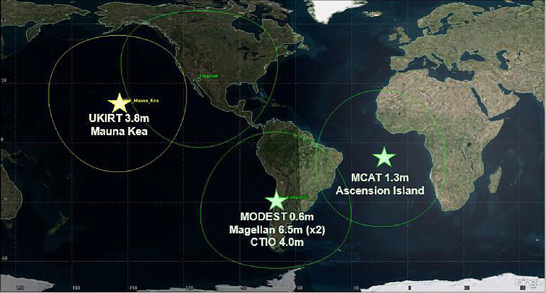
• NASA has successfully constructed the 1.3 m MCAT (Meter Class Autonomous Telescope) facility on Ascension Island in the South Atlantic Ocean (7º 58' 20" S, 14º 24' 4" W). MCAT is an optical telescope designed specifically to collect ground-based data for the statistical characterization of orbital debris ranging from LEO, MEO, GEO and GTO (GEO Transfer Orbit). The location of Ascension Island has two distinct advantages. First, the near-equatorial location fills a significant longitudinal gap in the GEODSS (Ground-based Electro-Optical Deep Space Surveillance) network of telescopes, and second, it allows access to objects in Low Inclination Low-Earth Orbits. 45)
- The MCAT facility is controlled by a sophisticated software suite that operates the dome and telescope, assesses sky and weather conditions, conducts all necessary calibrations, defines an observing strategy (as dictated by weather, sky conditions, and the observing plan for the night), and carries out the observations. It then reduces the collected data via four primary observing modes ranging from tracking previously cataloged objects to conducting general surveys for detecting uncorrelated debris. Nightly observing plans, as well as the resulting text file of reduced data, will be transferred to and from Ascension, respectively, via a satellite connection. Post-processing occurs at NASA/JSC ( Johnson Space Center).
- Construction began in September 2014 with dome and telescope installation occurring in April through early June, 2015. Engineering first light occurred on June 2, 2015; scientific first light was achieved on Aug 25, 2015. Acceptance testing, full commissioning, and calibration of this soon-to-be fully autonomous system commenced in summer 2015.
- MCAT is operated by the JSC / ODPO (Orbital Debris Program Office). From an observational perspective, the ODPO currently has access to telescopes on Mauna Kea (Hawaii) with the 3.8 m infrared UKIRT (United Kingdom Infra-Red Telescope) as well as in Chile where the optical MODEST (Michigan Orbital Debris Survey Telescope), CTIO (Cerro Tololo Interamerican Observatory) 4.0 m Blanco (optical), and Las Campanas Magellan (twin 6.5 m optical/infrared) telescopes are located (Figure 31).
- During the initial MCAT commissioning phase, 11 LEO objects, one MEO, and two GEO objects were observed, demonstrating the ability to easily track a multitude of earth-orbiting objects at all regimes. Designed to be fully automated, MCAT software is built to monitor weather, intelligently observe only when conditions allow, observe in four distinct modes, process data, and output a file with detected objects each night for further analysis at NASA JSC. All this is made possible due to the marriage of sophisticated automated software, a suite of weather sensors, advanced instrumentation, a fast tracking telescope and dome, and a very dedicated team of engineers and scientists.
• Since December 2010, KASI (Korea Astronomy and Space Science Institute) has been in the process to develop OWL-NET (Optical Wide-field patroL Network), an optical satellite tracking system of Korea for SSA monitoring. The primary objectives of OWL-Net are to monitor and to protect national space assets. OWL-NET has three goals: 46) 47) 48)
1) the optical tracking of domestic low earth orbit (LEO) satellites
2) the monitoring of the Geostationary Orbit (GEO) belt above Korea, and
3) the establishment and operation of a space debris collision risk-prediction and management system.
- Each OWL telescope is comprised of a 0.5 m class Ritchey-Chretien optics element and a 4 k CCD that covers a 1.4º x 1.4º FOV with a plate scale of 1.2 arcsec/pixel. The final limiting magnitude is estimated to be about 16 in the Johnson R-band. The network will be operated in fully autonomous mode with a minimum human intervention. In 2012, a prototype of the 0.5 m telescope system was successfully installed at the test bed site on the KASI campus.
- The installation of the telescope systems at three designated sites started in the first phase of the project (2011-2014) and the "OWL basic network" is in nominal operations from mid-2015 onwards. In the second phase of the OWL Project,Korea plans to place two additional 0.5 m class wide-field telescopes and to build a 2 m telescope system to complete the OWL network.
- The current three OWL-NET sites are at Daejeon, Korea, in Mongolia and in Morocco (Figure 32).
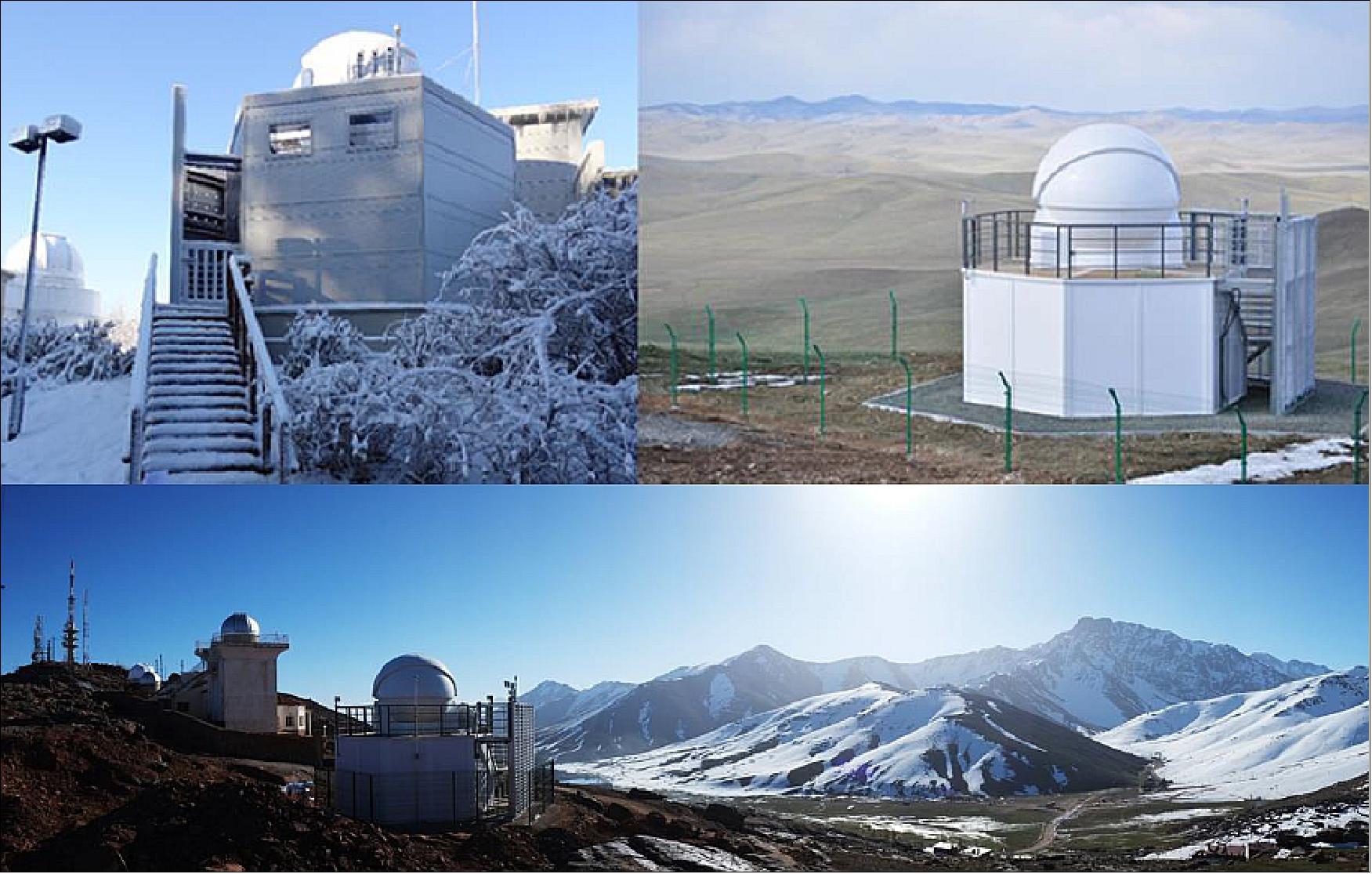
- Further OWL-NET sites of KASI will be installed at the Wise Observatory in Israel, at the University of Arizona (Mount Lemmon Observatory), USA, and a second OWL-NET site at the Oukaimeden Observatory, Morocco. During the calibration/validation phases so far, the OWL-NET team experienced various glitches on the hardware and the software of the system in operation. In addition, the team experienced many operational issues. The system at the two OWL-NET observatories has been struck by the frequent power outages on the sites, and it suffered from slow Internet speed and unstable connections available. Also, the weather plays a major role on many malfunctions, especially lightning. The team lost several components by lightning, even after implementing many countermeasures. Some unresolved issues remain.
A crucial aspect of SSA activities is international cooperation, which is becoming increasingly important. Through the research and development of the architecture design for Korean SSA system, it is expected that the development of SSA capability will be based on international collaboration.
• AEOS (Advanced ElectroOptical System): AEOS is a ground-based 3.67 m telescope space surveillance system specifically designed to improve the means of collecting, and the quality of, space data at the Maui Space Surveillance Complex facility in Hawaii. Primarily intended for DoD (Department of Defense) space surveillance missions, the telescope is also used by scientific and academic astronomy communities from across the United States. 49) 50)
- The origins of AEOS began in the middle of the 1980s. At that time, the Air Force was trying to develop a ground-based laser anti satellite capability. Maui appealed to AEOS planners for several reasons. Its maritime location, coupled with its 3000 m altitude, clear visibility, and location near the equator, made Haleakala a very stable environmental candidate. Taken together, these advantages made the site superb for routine observation of space objects. Work in support of the Western Test Range out of Vandenberg Air Force Base, California, and Barking Sands Missile Range on Kauai Island, Hawaii, and restricted airspace in this part of the Pacific Ocean also enhanced the site’s ability to meet its mission. The existing facilities at the Maui Space Surveillance Complex included the 1.6 m telescope, 1.2 m twin telescopes, Laser Beam Director, Beam Director/Tracker, and the GEODSS (Ground-based Electro-Optical Deep Space Surveillance System), as well as a proximity to the MHPCC (Maui High Performance Computing Center), made Maui even more attractive.
- When the program started, the AEOS mission was to support space test and tracking missions for U.S. Space Command. In the past, radar-based imaging techniques had been favored by U.S. Space Command over electrooptical methods. However, electrooptical systems could produce photographic images, while radar could not. These photographic images were more amenable to the human eye than those produced through radar signatures. Benefits expected from the AEOS and enhanced Maui Space Surveillance System included mission payload assessment and space object identification for Air Force Space Command, adaptive optic research for the AFRL (Air Force Research Laboratory), and use by government agencies and the national and international astronomy communities.
• Radar probing is the most powerful means of studying the LEO (Low Earth Orbit) satellite and space debris environment. There is no other technique capable of providing high-fidelity observations on the large number of objects in LEO. The radars comprising the US SSN (Space Surveillance Network), are high-resolution systems that contribute the bulk of the publicly available information on the space environment. 51)
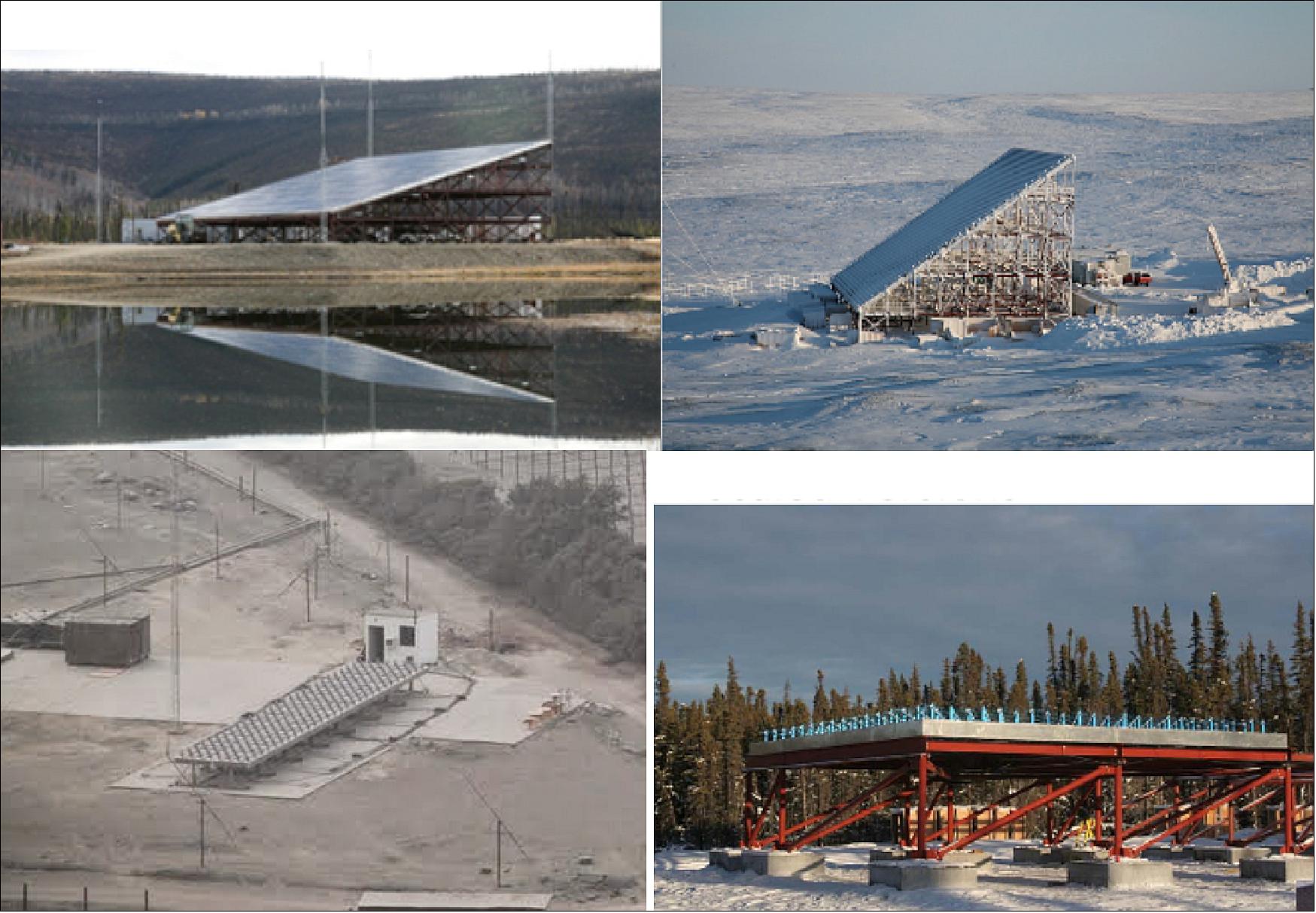
- The U.S. NSF (National Science Foundation) and the European Incoherent Scatter Scientific Association (EISCAT) operate a network of Geospace Facilities used to probe the upper atmosphere and ionosphere. The US network consists of high-power, large-aperture, sensitive radars including the L-band Sondrestrom radar in Greenland, the UHF Millstone Hill Radar in Massachusetts, the UHF Arecibo Observatory in Puerto Rico, and the VHF Jicamarca Radio Observatory in Peru. Most recently, the NSF funded the design and construction of a modern phased-array radar called the AMISR (Advanced Modular Incoherent Scatter Radar). AMISR systems are UHF phased-array radars comprised of building-block-like panels for modularity and relocatability, designed with the intention of deploying systems to many locations to pursue new avenues of scientific research.
- The AMISR systems are completely remotely operated and allow for pulse-to-pulse beam steering over their FOV (Field of View), resulting in great flexibility for satellite and debris studies. Moreover, the flexible software-based operations allow for the interleaving of different experiments on a pulse-to-pulse basis. This capability has been applied for the purposes of detecting and refining the orbits of satellites and space debris that appear in the public catalog.
- AMISR systems are modular, remotely operated, UHF 2D phased-array radars comprised of a number of building block-like panels. SRI International (Menlo Park, CA), with funding from the NSF, developed the AMISR technology. SRI designed, constructed, and now operates and manages, two AMISR facilities that are used to study the upper atmosphere and observe space-weather events. One operates at the Poker Flat Research Range in Alaska, and is named PFISR (Poker Flat Incoherent Scatter Radar). It was deployed in 2006. Two AMISR faces have been deployed to Resolute Bay, Nunavut, Canada and are named RISR-N (Resolute Bay Incoherent Scatter Radar) and RISR-C.
- AMISR’s modular configuration was designed for relative ease of relocation so that upper atmospheric activity can be studied around the globe. Remote operation and electronic beam steering allow researchers to operate and position the radar beam on a pulse-to-pulse basis to accurately measure rapidly changing space-weather events. AMISR is the only ISR ( Incoherent Scatter Radar) in operation capable of electronic pulse-to-pulse beam steering, and this is enabled by the phased-array antenna. This rapid steering capability allows scientists to resolve temporal/spatial ambiguities inherent in measurements from mechanically steered dish-based systems. PFISR is continuously operated and has an uptime of greater than 95%. This is especially significant since the system is based on remote, unattended operations in an arctic environment. Smaller AMISR systems have been deployed at the HAARP (High Altitude Auroral Research Program) in Gakona, Alaska and at the Jicamarca Radio Observatory outside of Lima, Peru.
- AMISR’s electronic steering capability enables it to observe greater than 4000 satellites per hour. Its scientific heritage gives it the ability to precisely correct for ionospheric delays in satellite measurements, one of the major sources of range biases at UHF. These corrections, and its large peak power, enables AMISR to track satellites with 20-meter range resolution. AMISR was designed to be highly redundant and
remotely operated so that systems can be placed around the globe in locations of interest for science. The data products will be of use to satellite operators interested in high quality, prioritized satellite and debris observations (Ref. 51).
• A rather vivid description of space congestion is the so-called Kessler syndrome, proposed by Donald J. Kessler and Burton G. Cour-Palais of NASA/JSC in 1978. It is a scenario, in which the density of objects in LEO is high enough that collisions between objects could cause a cascade—each collision generating space debris that increases the likelihood of further collisions. One implication is that the distribution of debris in orbit could render space activities and the use of satellites in specific orbital ranges unfeasible for many generations. 52) 53)
- The Kessler syndrome is especially insidious because of the "domino effect" and "feedback runaway" wherein impacts between objects of sizable mass spalls off debris from the force of collision. The shrapnel can then hit other objects, producing even more space debris: if a large enough collision or explosion were to occur, such as between a space station and a defunct satellite, or as the result of hostile actions in space, then the resulting debris cascade could make prospects for long-term viability of satellites in low earth orbit extremely low.
• Orbital debris — by definition all non-functional man-made objects, including fragments and elements thereof, in Earth orbit or reentering into Earth's atmosphere — is a threat to all functioning spacecraft: Orbital debris can instantly destroy or disable spaceborne resources. A collision with a high-speed 10 cm object would catastrophically damage a typical satellite, a 1 cm object would likely disable a spacecraft or penetrate the shields of the International Space Station, and a 1 mm object could destroy satellite subsystems. Once a risk of collision has been identified, the only effective way to mitigate the risk is to move the spacecraft out of the way. Moving a satellite, however, entails costs. Avoidance maneuvers cost fuel, shorten a spacecraft’s lifetime, and may disrupt data and service continuity. 54)
• As of 2013, scientific models estimate the total number of space debris objects in Earth orbit to be in the order of:
- 29,000 - for sizes larger than 10 cm
- 670,000 - for sizes larger than 1 cm
- More than 170 million - for sizes larger than 1 mm.
• Debris policies and spacecraft removal from orbit at end-of-life: A principal forum for debating orbital debris issues and new practices (including debris mitigation measures) is the IADC (Inter-Agency Space Debris Coordination Committee), created in 1993 by government representatives from USA (NASA), Europe (ESA, ASI, BNSC (now UKSA), CNES, DLR), Russia (Roskosmos), Japan (JAXA), India (ISRO, since 1995), China (CNSA, since 1995), and the Ukraine (NSAU, since 2000), Canada (CSA, since 2010), Korea (KARI since 2014). 55) 56)
- In 2002, IADC completed a set of debris mitigation guidelines agreed to by the agencies. In Feb. 2003, these guidelines were presented to UNCOPUOS (United Nations Committee on Peaceful Uses of Outer Space) for review and approval.
- In 2007, UNCOPUOS adopted a set of Space Debris Mitigation Guidelines. Subsequently, in 2008, France adopted a national space law, the European Union drafted a code of conduct for outer space activities, and ESA adopted a binding set of requirements on space debris mitigation for their space projects.
- Compliance with debris mitigation measures, such as the “25-year rule”, is the first defense against the increase of orbital debris. The 25-year rule for LEO spacecraft is an international understanding related to post-mission disposal. It stipulates that nations should not launch an object whose lifetime in space will exceed 25 years after the completion of its mission.
- At its 27th meeting in 2009, the IADC adopted a new Action Item (AI 27.1) to assess:
1) the stability of the LEO space object population and
2) the need to use ADR (Active Debris Removal) to stabilize the future LEO environment.
- The Action Item was undertaken by IADC Working Group 2 (Environment and Data Bases). The principal participants in the study were ASI, ESA, ISRO, JAXA, NASA, and UKSA.
- In addition to the 25-year rule, the IADC has recommended that if a satellite has a 1-in-10,000 chance of surviving atmospheric reentry, its reentry must be controlled so that it occurs over unpopulated areas.
• Debris removal from space: A first analysis on the stability of the current environment independent of human measures was conducted by NASA in 2009, which examined a future scenario in which no further objects are added to the space environment (i.e. no launches, no debris release). The results, which are confirmed by ESA’s simulations, show that the number of debris objects would continue to grow even under these idealized conditions – under which a collision rate of once every 10 years can be assumed.
- This is a clear indicator that the population of large and massive objects has reached a critical density in LEO. In turn, this means that the number of large and massive (mostly physically intact) objects must be reduced.
- Studies at NASA and ESA show that with a removal sequence planned according to target mass, the environment can be stabilized when on the order of 10 objects are removed from LEO per year.
1) The selected objects should have a high mass (they have the largest environmental impact in case of collision)
2) Should have high collision probabilities (e.g. they should be in densely populated regions)
3) Should be in high altitudes (where the orbital lifetime of the resulting fragments is long).
• As of 2015, ESA has plans to remove its defunct Envisat spacecraft of 8 tons from orbit. Envisat is drifting in its polar orbit of 800 km since contact with the spacecraft was unexpectedly lost in early April 2012 and the end of the mission was declared on May 9, 2012. It is the planned target of ESA’s proposed e.Deorbit mission, intended to pioneer the concept of space debris removal. Due for launch in 2021, e.Deorbit will rendezvous with the lost satellite and then secure it for a controlled atmospheric reentry. -The aim now is to bring e.Deorbit to a point where it is essentially ready to build if ESA’s Council of Ministers in December 2016 gives its assent for launch in 2021. 58)
Commercial SSA Service Providers
Improvements in information technology have also helped to fuel demand for commercial data on satellites and space junk. As satellites proliferate, defense contractors are starting to supplement government tracking of orbital debris. In 2015, the commercial market is still in its infancy, but growing fast. 59) 60)
• ComSpOC (Commercial Space Operations Center) of AGI (Analytical Graphics Inc.), Exton, PA, opened in March 2014 to track active satellites and ‘space junk’. ComSpOC relies on observations from a larger network of ‘off the shelf’ sensors around the globe. These include eight optical sites, three radio-frequency tracking sites and two radar installations. The center purchases many of its data from outside contractors that run the observation sites. 61)
- In Q3 2015, ComSpOC is tracking 6,000 to 7,000 objects, including active and inactive satellites and debris. This is significant less than what the USAF is tracking, but ComSpOC's quarry includes nearly all significant objects in GEO. AGI plans to bring two more radar facilities online next year, which should allow the company to track more objects in LEO where the largest population of satellites and debris is found.
- AGI's SSA software suite delivers SSA capabilities in a service-oriented architecture designed for scalability, reliability, full-database integration, secure operations and web-based user interactions. ComSpOC provides commercial satellite owner/operators and government space operations centers with persistent day/night tracking of space objects in Earth orbit. 62) 63) 64) 65)
• Aug. 25, 2014: Under a new strategic cooperation agreement, Lockheed Martin of Denver, CO and EOS (Electro Optic Systems Pty. Ltd.) of Canberra, Australia are developing a new space object tracking site in Western Australia that will paint a more detailed picture of space debris for both government and commercial customers. 66)
- The site will use a combination of lasers and sensitive optical systems like those found in telescopes to detect, track and characterize man-made debris objects. Electro-optical technologies that can zoom in on specific objects form a strong complement to radar-based systems like the U.S. Air Force’s Space Fence, which will sweep the sky and track 200,000 objects.
- Electro Optic Systems develops and produces a wide range of space-related technologies including telescopes and beam directors. They are among the largest producers of major optical telescopes in the world, and currently operate the Space Research Center, a satellite laser ranging and debris tracking facility, at Mt. Stromlo in the Australian Capital Territory.
- Dec. 1, 2015: The network in development by EOS and Lockheed Martin, called OSSTM (Optical Space Services),have broken ground on a new space object tracking facility in Australia. The expansion of space debris tracking by EOS and Lockheed Martin is expected to make a significant contribution to the preservation of the space environment, by providing data to commercial and government customers which will enable cost-effective debris maneuver for satellites. EOS expects to commence the delivery of data and services by late 2016. OSS is designed to complement the radar-based tracking such as the USAF Space Fence and is expected to operate in 2022. 67)
• Nov. 16, 2015: The USAF (USSTRATCOM), which has long relied on its own sensors to feed space situational awareness data to the JSpOC (Joint Space Operations Center) at Vandenberg Air Force Base, recently began a pilot program known as the ”Commercial Integration Cell” to get more-refined data from commercial satellite operators. 68) 69)
- In its Nov. 4 request to industry, the Air Force said the data it seeks must “provide a threat analysis for specified high interest U.S. satellites, depicting time and distance, as well as required time for a specified threat to maneuver into a threatening position.” It also must “provide predicted and real time characterization of all launch and early orbit operations, to include direct ascent anti-satellite (ASAT) threats, by determining orbital trajectories, [and] projected conjunctions with projected launch vehicle path.”
- In the past year, the Defense Department has been rapidly expanding the amount and type of space situational awareness data it gets from industry. The information will be used in a new space operations center, known as the JICSpOC (Joint Interagency Coalition Space Operations Center) at Schriever Air Force Base in warfighting experiments, an Air Force official said. With the newly established JICSpOC, the Defense Department and intelligence community plan to run exercises to help prepare for future conflicts. 70)
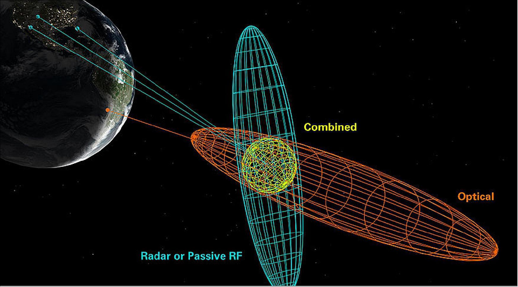
• December 11, 2015: DeSS (DEIMOS Sky Survey) is a new ground-based infrastructure owned by Elecnor Deimos, and it is devoted for the observation within the field of SST (Space Surveillance and Tracking) and NEO. This site is currently in commissioning phase and final set-up on Niefla mountain in the center of Spain, close to DEIMOS Castilla La Mancha premises. DeSS includes three optical sensors: two telescopes for observing high orbital regimes in surveillance and tracking modes and a third devoted to the observation of LEO orbital regime and fast moving NEO objects. 71)
- The new DeSS tracked the LISA Pathfinder spacecraft in orbit about 11 000 km above the center of Earth.
References
1) Joseph A. Haimerl, Gregory P. Fonder, ”Space Fence System Overview,” Proceedings of the 16th AMOS (Advanced Maui Optical and Space Surveillance Technology Conference), Maui, Hawaii, USA, Sept. 15-18, 2015, URL: http://www.amostech.com/TechnicalPapers/2015/SSA/Haimerl.pdf
2) Brian Weeden, ”2007 Chinese Anti-Satellite Test Fact Sheet, ” Nov. 23, 2010, URL: http://swfound.org/media/9550/chinese_asat_fact_sheet_updated_2012.pdf
3) J.-C. Liou, “USA Space Debris Environment, Operations, and Measurement Updates,” 52nd session of the Scientific and Technical Subcommittee, UNOOSA (United Nations Office for Outer Affairs), Vienna, Austria, Feb. 2-13, 2015, URL: http://www.unoosa.org/pdf/pres/stsc2015/tech-28E.pdf
4) ”Orbital Debris Quarterly News,” NASA, Volume 19, Issue 1, January 2015, URL: http://orbitaldebris.jsc.nasa.gov/newsletter/pdfs/ODQNv19i1.pdf
5) “USA Moves Ahead with Next-Generation 'Space Fence' Tracking,” Defense Industry Daily, June 2, 2011, URL: http://www.defenseindustrydaily.com
/Air-Force-Awards-First-Phase-of-Next-Generation-Space-Fence-05511/
6) “Lockheed Martin Space Fence Radar Prototype Tracking Orbiting Objects,” March 8, 2012, URL: http://www.lockheedmartin.com/us/news/press-releases/2012
/march/0306-ms2-space-fence-radar-prototype-tracking-orbiting-objects.html
7) “Lockheed Martin Submits Space Fence Radar Proposal to USAF to Detect and Track Orbital Objects,” Space Daily, Nov. 15, 2012, URL: http://www.spacedaily.com/reports/Lockheed_Martin_Submits_
Space_Fence_Radar_Proposal_to_USAF_to_Detect_and_Track_Orbital_Objects_999.html
8) http://www.lockheedmartin.com/us/products/space-fence.html
9) Stephen Clark, “Lockheed Martin wins contract for Space Fence,” Spaceflight Now, June 2, 2014, URL: http://www.spaceflightnow.com/news/n1406/02spacefence/#.U5moeXa4Ri0
10) ”Space Fence,” Lockheed Martin, URL: http://www.lockheedmartin.com/us/products/space-fence.html
11) ”Space Situational Awareness Efforts and Planned Budgets - Information Presented to the Senate Armed Services Committee,” GAO (Government Accounting Office), Aug. 10, 2015, URL: http://www.gao.gov/assets/680/672987.pdf
12) Linda Haines, Phillip Phu, “Space Fence PDR Concept Development Phase”, Proceedings of AMOS (Advanced Maui Optical and Space Surveillance Technologies Conference), , Maui, Hawaii, USA, September 13-16, 2011
13) ”Lockheed's Space Fence Program Completes Critical Design Review,” Lockheed Martin Press Release, Sept. 28, 2015, URL: http://www.lockheedmartin.com/us/news/press-releases/2015
/september/150928-mst-space-fence-program-completes-critical-design-review.html
14) ”Space Fence Now Operational,” Satnews Daily, 30 March 2020, URL: http://www.satnews.com/story.php?number=968027671
15) ”State-of-the-Art Space Fence Radar Enters Government-led Trial Period as it Nears Operational Acceptance,” Los Angeles Air Force Base, 10 December 2019, URL: https://www.losangeles.af.mil/News/Article-Display/Article/2036720
/state-of-the-art-space-fence-radar-enters-government-led-trial-period-as-it-nea/
16) ”The First to Sign ... Cal Poly Signs SSA Agreement with USSTRATCOM,” Satnews Daily, 26 September 2019, URL: http://www.satnews.com/story.php?number=378736465
17) Pat Host, ”Space Fence mission change has US Air Force rethinking second radar site,” Jane's Defence Weekly, 21 June 2019, URL: https://www.janes.com/article/89438
/space-fence-mission-change-has-us-air-force-rethinking-second-radar-site
18) ”U.S. Air Force's Space Fence Detects Debris from India Anti-Satellite Test,” PR Newswire, 22 May 2019: URL: https://www.prnewswire.com/news-releases
/us-air-forces-space-fence-detects-debris-from-india-anti-satellite-test-300855202.html
19) Debra Werner, ”Lockheed Martin prepares to turn on U.S. Air Force Space Fence on Kwajalein Atoll,” Space News, 3 May 2018, URL: https://spacenews.com
/lockheed-martin-prepares-to-turn-on-u-s-air-force-space-fence-on-kwajalein-atoll/
20) Jason B. Cutshaw, ”Huntsville center prepares to facilitate Space Fence,” USASMDC/ARSTRAT, Nov. 15, 2016, URL: https://www.army.mil/article/178533/huntsville_center_prepares_to_facilitate_space_fence
21) Kameron J. Simon, John P. Morse, Gegory P. Fonder, ”AN/FSY-3: Space Fence System Overview of User Interface and Conjunction Assessment Study,” SSA Operators' Workshop, Denver, Colorado, Nov. 3-5, 2016, URL: https://advancedssa.com/assets/img
/workshop/presentations/SpaceFence_2016SSAOperatorsWorkshop.pdf
22) Peter J. Hack, Ken Carbaugh, Kameron J. Simon, ”Automated Space Surveillance using the AN/FSY-3 Space Fence System,” Proceedings of the 17th AMOS (Advanced Maui Optical and Space Surveillance Technology Conference), Maui, Hawaii, USA, Sept. 20-23, 2016, URL: http://www.amostech.com/TechnicalPapers/2016/Poster/Hack.pdf
23) ”General Dynamics Completes U.S. Air Force Space Fence Radar Array Ground Structure,” General Dynamics, April 7, 2016, URL: http://www.generaldynamics.com/news/press-releases
/2016/04/general-dynamics-completes-us-air-force-space-fence-radar-array-ground
24) ”Construction Underway for U.S. Air Force Space Fence Radar in the Marshall Islands,” Lockheed Martin Press Release, March 22, 2015, URL: http://www.lockheedmartin.com/us/news/press-releases
/2015/march/150323-mst-iwss-construction-underway-for-us-air-force-space-fence-radar.html
25) Michael G. Koltiska, Han Du, Dan Prochoda, Kevin Kelly, ”AN/FSY-3 Space Fence System Support of Conjunction Assessment,” Proceedings of the 17th AMOS (Advanced Maui Optical and Space Surveillance Technology Conference), Maui, Hawaii, USA, Sept. 20-23, 2016, URL: http://www.amostech.com/TechnicalPapers/2016/Poster/Koltiska.pdf
26) Arthur Lue, ”The All-Versus-All Low Earth Orbit Conjunction Problem,” AMOS Conference, Maui, Hawaii, Sept. 13-16, 2011
27) Brian Weeden, ”The Importance of Space Situational Awareness and the Potential Role for Japan to Contribute,” JAMSS Space Diplomatic Study Group, Tokyo, Japan, June 24, 2014, URL: http://swfound.org/media/172630/bw_jamss_ssa_japan_june2014.pdf
28) ”Conjunction Data Message,” Recommended CCSDS standard, Blue Book June 2013, URL: http://public.ccsds.org/publications/BlueBooks.aspx
29) François Laporte, Stéphane Christy, Monique Moury, ”Collaborative Work Environment for Operational Conjunction Assessment,” Proceedings of the 16th AMOS (Advanced Maui Optical and Space Surveillance Technology Conference), Maui, Hawaii, USA, Sept. 15-18, 2015, URL: http://www.amostech.com/TechnicalPapers/2015/SSA/Laporte.pdf
30) Cheryl Pellerin, ”Stratcom, DoD Sign Space Operations Agreement With Allies,” DoD, Sept. 23, 2014, URL: http://www.defense.gov/News-Article-View/Article/603303
31) Joey Cheng, ”Stratcom signs space data agreement with U.K., Canada, Australia,” Defense Systems, Sept. 23, 2014, URL: https://defensesystems.com/articles/2014/09/23/us-multination-space-agreement.aspx
32) ”USSTRATCOM, Germany make arrangement to share space services, data,” Air Force Space Command, Jan. 29, 2015, URL: http://www.afspc.af.mil/news/story.asp?id=123437744
33) Mike Gruss, ”U.S. Strategic Command, ESA Sign Space Surveillance Data-sharing Agreement,” Space News, Oct. 31, 2014, URL: http://spacenews.com
/42384us-strategic-command-esa-sign-space-surveillance-data-sharing-agreement/
34) Tim Flohrer, Beatriz Jilete, Alexandru Mancas, Holger Krag, ”Conceptual Design for Expert Centers Supporting Optical and Laser Observations in an Space Surveillance and Tracking System,” Proceedings of the 16th AMOS (Advanced Maui Optical and Space Surveillance Technology Conference), Maui, Hawaii, USA, Sept. 15-18, 2015, URL: http://www.amostech.com/TechnicalPapers/2015/SSA/Flohrer.pdf
35) ”About SSA,” ESA, Oct. 29, 2015, URL: http://www.esa.int/Our_Activities/Operations/Space_Situational_Awareness/About_SSA
36) Giovanni M. Del Genio, Jacopo Paoli, Enrico Del Grande, Ferdinando Dolce, ”Italian Air Force Radar and Optical Sensor Experiments for the Detection of Space Objects in LEO Orbit,” Proceedings of the 16th AMOS (Advanced Maui Optical and Space Surveillance Technology Conference), Maui, Hawaii, USA, Sept. 15-18, 2015, URL: http://www.amostech.com/TechnicalPapers/2015/Adaptive_Optics_Imaging/DelGenio.pdf
37) Mike Gruss, ”U.S., France Expand Space Data-sharing Agreement,” Space News, April 16, 2015, URL: http://spacenews.com/us-france-expand-space-data-sharing-agreement/
38) ”Space Situational Awareness and the Sapphire Satellite,” CAF, Jan. 30, 2014, URL: http://www.forces.gc.ca/en/news/article.page?
doc=space-situational-awareness-and-the-sapphire-satellite/hr0e3oag
39) Elle Agnew, ”SSA – Cornerstone of the CAF Space Program,” 2015, URL: [web source no longer available]
40) Marc Boucher, Andre Dupuis, “An Overview of Canadian Military Space in 2014 - Part 2,” Space Ref Canada, Feb. 17, 2015, URL: http://spaceref.ca/military-space
/an-overview-of-canadian-military-space-in-2014---part-2.html
41) Yoshinori Kobayashi, ”Cooperation between Japan and Europe in the Space Situational Awareness (SSA) Field,” ESPI Perspectives No. 53, October 2011, URL: http://mercury.ethz.ch
/serviceengine/Files/ISN/133785/ipublicationdocument_singledocument
/401cb9b2-b0fd-43b6-809c-52e08d90374c/en/ESPI_Perspectives_53.pdf
42) Shizuo Yamamoto, ”Overview of JAXA Activities on Sustainable Space Development and Space Situational Awareness,” Feb. 26, 2015, URL: https://web.archive.org/web/20170829090925/http://www.jsforum.or.jp/debrisympo/2015/pdf/09S2DS2A2015_JAXA_KNote_0225.pdf
43) Gerard T. van Belle, ”Developing Geostationary Satellite Imaging at the Navy Precision Optical Interferometer,” Proceedings of the 16th AMOS (Advanced Maui Optical and Space Surveillance Technology Conference), Maui, Hawaii, USA, Sept. 15-18, 2015, URL: http://www.amostech.com/TechnicalPapers/2015/Optical_Systems/vanBelle.pdf
44) J. T. Armstrong, R. B. Hindsley, H. R. Schmitt, F. J. Vrba, J. A. Benson, D. J. Hutter, R. T. Zavala, ”Detection of a geostationary satellite with the Navy Prototype Optical Interferometer,” Proceedings of SPIE, Vol. 7734, 77343C-1, 2010, URL: http://www.dtic.mil/get-tr-doc/pdf?AD=ADA544862
45) S. M. Lederer, L. F. Pace, P. Hickson, T. Glesne, H. M. Cowardin, B. Buckalew, J. Frith, R. Maeda, D. Douglas, D. Nishimoto, E. G. Stansbery, ”Deploying the NASA Meter Class Autonomous Telescope on Ascension Island,” Proceedings of the 16th AMOS (Advanced Maui Optical and Space Surveillance Technology Conference), Maui, Hawaii, USA, Sept. 15-18, 2015, URL: http://www.amostech.com/TechnicalPapers/2015/Orbital_Debris/Lederer.pdf
46) ”Center for Space Situational Awareness,” KASI, Nov. 20, 2014, URL: http://creakier/english/Research/CenterforSpaceSituationalAwareness.aspx
47) Jung Hyun Jo, Jin Choi, Maru Park, Ju Young Son, Youngho Bae, Sun Youp Park, Jang Hyun Park, ”Early CAL/VAL process for an optical tracking system by Korea,” Proceedings of the 16th AMOS (Advanced Maui Optical and Space Surveillance Technology Conference), Maui, Hawaii, USA, Sept. 15-18, 2015, URL: http://www.amostech.com/TechnicalPapers/2015/Optical_Systems/Jo.pdf
48) Eun-Jung Choi, Sung-Ki Jo, Jang-Hyun Park, ”Architecture Design for the Space Situational Awareness System in the Preparedness Plan for Space Hazards of Republic of Korea,” Proceedings of the 16th AMOS (Advanced Maui Optical and Space Surveillance Technology Conference), Maui, Hawaii, USA, Sept. 15-18, 2015, URL: http://www.amostech.com/TechnicalPapers/2015/Poster/ChoiEun-Jung.pdf
49) ”Advanced ElectroOptical System,” USAF Fact Sheet, 2002, URL: http://www.kirtland.af.mil/shared/media/document/AFD-070404-028.pdf
50) ”Advanced Electro Optical System (AEOS),” URL: http://www.thelivingmoon.com
/45jack_files/03files/AEOS_Advanced_Electro_Optical_System.html
51) Michael J Nicolls, ”Space Debris Measurements using the Advanced Modular Incoherent Scatter Radar,” Proceedings of the 16th AMOS (Advanced Maui Optical and Space Surveillance Technology Conference), Maui, Hawaii, USA, Sept. 15-18, 2015, URL: http://www.amostech.com/TechnicalPapers/2015/Poster/Nicolls.pdf
52) ”Kessler syndrome,” Wikipedia, URL: https://en.wikipedia.org/wiki/Kessler_syndrome
53) Donald J. Kessler, Burton G. Cour-Palais, "Collision Frequency of Artificial Satellites: The Creation of a Debris Belt". Journal of Geophysical Research, Vol. 83, No A6, June 1, 1978,pp : 2637–2646, URL: http://webpages.charter.net/dkessler/files/Collision%20Frequency.pdf
54) Steven A. Hildreth, Allison Arnold, ”Threats to U.S. National Security Interests in Space: Orbital Debris Mitigation and Removal,” CRS (Congressional Research Service) Report, Jan. 8, 2014, URL: https://www.fas.org/sgp/crs/natsec/R43353.pdf
55) J. Yan, “20 Years of IADC,” Proceedings of the 51st Session of Scientific & Technical Subcommittee of UNCOPUOS, Vienna, Austria, Feb. 11-22, 2014, URL: http://www.unoosa.org
/pdf/pres/stsc2014/tech-32E.pdf
56) ”Stability of the Future LEO Environment,” Report of an IADC Study, 50th Session of the Scientific and Technical Subcommittee, UNCOPUOS, Feb. 11-22, 2013, URL: http://www.unoosa.org
/pdf/pres/stsc2013/tech-12E.pdf
57) ”Debris Removal,” ESA, April 19, 2013, URL: http://www.esa.int/Our_Activities/Operations/Space_Debris/Debris_removal
58) ”ESA heading towards removing space debris,” ESA, June 2, 2015, URL: http://www.esa.int/Our_Activities/Space_Engineering_Technology
/Clean_Space/ESA_heading_towards_removing_space_debris
59) Ilima Loomis, ”Private firms spy a market in spotting space junk,” Nature News, Sept. 23, 2015, URL: http://www.nature.com/news/private-firms-spy-a-market-in-spotting-space-junk-1.18425
60) Christopher J. Sullivan, Edward Pier, Scott Gregory, Michael Bush, ”Space Situational Awareness using Market Based Agents,” Proceedings of AMOS (Advanced Maui Optical and Space Surveillance Technology Conference), Maui, Hawaii, USA, Sept. 11-14, 2012, URL: http://www.amostech.com/TechnicalPapers/2012/Data_Services/SULLIVAN.pdf
62) ”Space Situational Awareness,” AGI, January 9, 2016, URL: http://www.agi.com/solutions/SSA/
63) ”AGI Receives Operational Upgrade Award for the Joint Space Operations Center Mission System (JMS) Program,” AGI Press Release, January 8, 2014, URL: http://www.agi.com
/media-center/press-releases/display.aspx?id=961
64) ”AGI Software for Space Situational Awareness,” AGI, URL: http://www.agi.com/downloads/resources/white-papers/AGI-SSA-Whitepaper.pdf
65) Thomas M. Johnson, ”SSA Sensor Calibration Best Practices,” Proceedings of the 16th AMOS (Advanced Maui Optical and Space Surveillance Technology Conference), Maui, Hawaii, USA, Sept. 15-18, 2015, URL: http://www.amostech.com/TechnicalPapers/2015/Poster/JohnsonT.pdf
66) ”Lockheed Martin And Electro Optic Systems To Establish Space Debris Tracking Site In Western Australia,” Lockheed Martin Press Release, Aug. 25, 2014, URL: http://www.lockheedmartin.com/us/news/press-releases/2014/august/0825-ss-electro.html
67) ”A Closer Look at Space Debris: Lockheed Martin and Electro Optic Systems Break Ground on Australian Space Tracking Site,” Lockheed Martin Press Release, Dec. 1, 2015, URL: http://www.lockheedmartin.com/us/news
/press-releases/2015/december/121201-ssc-EOS-announcement.html
68) Mike Gruss, ”U.S. Air Force Seeks New Space Situational Awareness Data To Track Threats,” Space News, Nov. 16, 2015, URL: http://spacenews.com
/u-s-air-force-seeks-new-space-situational-awareness-data-to-track-threats/
69) Caleb Henry, ”JFCC Space Details Commercial Integration Cell Goals,” Satellite Today, July 20, 2015, URL: http://www.satellitetoday.com/regional/2015/07/20
/jfcc-space-details-commercial-integration-cell-goals/
70) ”New Joint Interagency Combined Space Operations Center to be established,” DoD, Release 352-15, Sept. 11, 2015, URL: http://www.defense.gov/News/News-Releases/News-Release-View
/Article/616969/new-joint-interagency-combined-space-operations-center-to-be-established
71) ”Elecnor Deimos observatory DEIMOS Sky Survey (DeSS) has tracked LISA Pathfinder,” Elecnor Deimos, Dec. 11, 2015, URL: https://web.archive.org/web/20160801082756/http://www.deimos-space.com/en/noticias/showNew.php?idNew=212
The information compiled and edited in this article was provided by Herbert J. Kramer from his documentation of: ”Observation of the Earth and Its Environment: Survey of Missions and Sensors” (Springer Verlag) as well as many other sources after the publication of the 4th edition in 2002. - Comments and corrections to this article are always welcome for further updates (eoportal@symbios.space).
Solution Program Status Capabilities and partnerships References Back to top