SMM (Solar Maximum Mission)
Non-EO
NASA
GSFC
Quick facts
Overview
| Mission type | Non-EO |
| Agency | NASA, GSFC |
SMM (Solar Maximum Mission)
Overview
SMM was an early NASA/GSFC solar mission. The objectives were to support studies of solar flares (trigger mechanisms) and related phenomena over a wide band of wavelengths in the UV, X-ray and gamma-ray regions of the spectrum; coverage of the maximum period of a sunspot cycle; to gain a better understanding of the violent nature of the sun and its effects on the Earth; measurement of radiation fluxes. The SMM observations were coordinated with in situ measurements of flare particle emissions made aboard the ISEE 3 spacecraft. 1) 2) 3) 4) 5)
Spacecraft
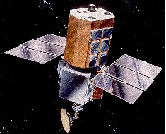
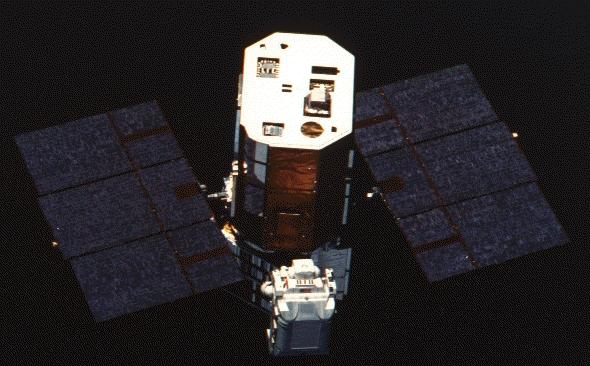
SMM is of modular bus design (built by Fairchild), referred to as the MMS (Multimission Modular Spacecraft); the MMS design was developed in the 1970s, and was also used for the Landsat 4 and 5, TOPEX/Poseidon, UARS, and the EUVE missions.
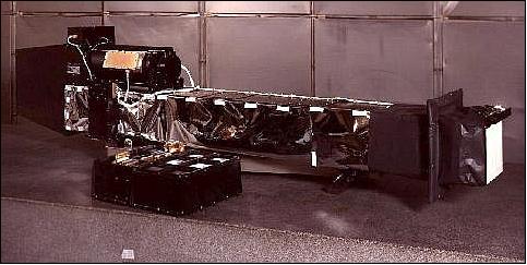
The spacecraft measured approximately 4 m in length, fitting into a circular envelope 2.3 m in diameter. The instrument module occupied the top 2.3 m and contained the solar payload instruments together with the fine-pointing sun-sensor system. Below the instrument module was the MMS containing the subsystems for attitude control (ACS), power, communication and data handling (C&DHS). Between the instrument module and the MMS is the transition adaptor, supporting two fixed solar paddles that supply between 1500 and 3000 W of power. Satellite mass = 2315 kg. 6) 7) 8) 9)
RF communications
Onboard storage of science data was provided. S-band downlink at 2287.5 GHz. The downlink for science data was considerably improved with the availability of TDRS in April 1983. Data from ground-based sun observations (collation of telescopic data and magnetograms with Solar Max's maps) served as forecast event-predictions on the sun for instrument precision pointing setup of the flare watch on the actual flare site.
Launch
The launch of SMM took place on Feb. 14, 1980 with a Thor-Delta vehicle from Cape Canaveral, FLA.
Orbit
circular Earth orbit, apogee = 512 km, perigee = 508 km, inclination = 28.5º, period = 96 min (the S/C spends about 60 min of each orbit in full view of the sun).
Note: After the serving mission in April 1984, the orbit of SMM was considerably lower than the initial one, namely at an altitude of 405 km x 408 km with an inclination of 28.5º and a period of 92.7 min.
Mission Status
• The SMM spacecraft reentred the Earth's atmosphere on December 2, 1989 (latitude 3.1º North, longitude 88.6º East). The coronagraph generated ~240,000 images of the solar corona before its fiery demise.
• The SMM mission provided solar observations until Nov. 17, 1989. Launched during a period of maximum solar activity (Feb. 14, 1980), SMM observed more than 12,000 flares and over 1,200 coronal mass ejections during its lifetime. 10)
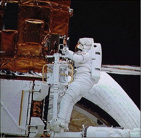
• SMM servicing mission: NASA opted for a Shuttle mission to repair the SMM spacecraft (to test also the potential of the Shuttle fleet applications). Then, on April 11, 1984 SMM became the first satellite in history to be retrieved, repaired, and redeployed in orbit by a Shuttle crew (Challenger, STS-41C, April 6-13, 1984). The SMM spacecraft was captured on April 10 with the RMS (Remote Manipulator System), the robot arm of the Shuttle, provided/built by Canada. The Shuttle crew was able to restore the spacecraft's malfunctioning attitude control system and replaced a failed electronics box for the coronagraph/polarimeter. The opportunity was also used to replace in orbit a dish antenna, enabling SMM to transmit its data via TDRS-1 (this repair job required over 6 hours of EVA by two astronauts, George D. Nelson and James D. A. van Hoften).
However, after mission repair, the orbit of SMM was considerably lower than the initial one, namely at an altitude of 405 km x 408 km with an inclination of 28.5º and a period of 92.7 min.
• SMM performed flawlessly until an attitude-control system failure (actually a failure of a fuse) occurred in the solar pointing system in the time frame Dec. 1980 - Jan. 1981, which kept the S/C from pointing precisely at the sun. However, good sun-pointing was needed for the solar payload of SMM.
Sensor Complement
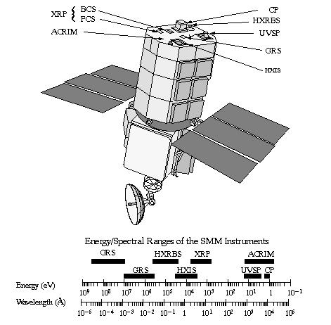
There were seven instruments on board the spacecraft, covering a wide spectral range, from white light to gamma rays. 11) 12)
ACRIM-I (Active Cavity Radiometer Irradiance Monitor-I)
The ACRIM-I instrument was designed and developed at NASA/JPL; PI: R. C. Willson, JPL. Objective: regular long-term observations of the TSI (Total Solar Irradiance) commonly referred to as the “solar constant”. The goals of the experiment are: 13) 14)
1) To begin a long-term climatological database on solar irradiance variability
2) To provide a shorter-term database for solar physics investigations.
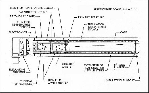
ACRIM-I has three active cavity radiometer (ACR) type IV sensors. The instrument views the sun through a 5º (full angle) field of view. ACRIM-I uses a black-body cavity to measure the total solar irradiance of the visible hemisphere of the sun.
ACRIM is a cavity pyrheliometer with a conical-cavity detector, a shutter that can block solar radiation, and a reference cavity that permanently views a surface at the temperature of a heat sink. A servo system maintains the observing cavity at a temperature slightly above that of the reference cavity. Measurements consist of voltage determinations for the heater circuit in this servo loop. A difference between shutter-open and shutter-closed readings, normally obtained in a two-minute cycle, then provides a measurement of solar irradiance. Hence, the solar irradiance at the Earth is proportional to the difference between the heating rates with shutter open and closed. 15) 16)
In Figure 5, the triangles in the body of the modules are the conical sensors. The primary cavity views the sun when the shutter in front of it (not shown) is open. The secondary cavity serves as a thermal reference to the primary cavity. The primary aperture provides a precisely measured opening that defines the surface area that the incoming light hits. The measurement the sensor produces is in W/m2 (power/area). 17)
The ACRIM experiment operated in the electrically self-calibrated mode to realize maximum accuracy and precision. A measurement precision of better than ± 0.002% was sustained while operating in the self-calibrated mode during the first 300 days of (normal) SMM operations. Two of ACRIM-I's three cavity sensors were kept shuttered most of the time; they were used sparingly to calibrate degradation of the continuously monitoring sensor.
After the ERB (Earth Radiation Budget) sensor on Nimbus-7 (launch Oct. 24, 1978), ACRIM-I represents also a pioneering instrument for the measurement of Earth's radiation budget [it is in fact the second instrument anywhere utilizing the ESCC (Electrically Self Calibrating Cavity) technique]. ACRIM-I showed that the sun is actually brighter during the maximum of the sunspot cycle when more spots are observed on the sun's surface. Although the sunspots themselves are dark and produce dimming, they are surrounded by faculae that are bright and, on average, more than offset the dimming due to the sunspots. ACRIM-I detected a short-term (less than 27-day solar rotational period) irradiance variability of as much as 0.2% and a long-term variability of about 0.1%.
ACRIM I was the first instrument to clearly show that the energy from the sun is not a constant value but instead varies over time. These energy changes are small but significant and they cycle approximately every 11 years (solar cycle).
Note: The ACRIM instrument experienced later a number of improvements and reflights on the following missions:
• ACRIM-II was flown on the following Shuttle missions, each time in parallel with the SOLCON instrument: STS-45 (March 24 - April 2, 1992, referred to as ATLAS-1); STS-56 (April 8-17, 1993, referred to as ATLAS-2); STS-66 (Nov. 3-14, 1994, referred to as ATLAS-3)
• ACRIM-II is also flown on the UARS (Upper Atmosphere Research Satellite) mission (launch Sept. 12, 1991) - providing over 10 years of continuous observations.
• ACRIM-III is flown on ACRIMSat (launch Dec. 20, 1999) and fully operational in 2011.
CP (Coronagraph/Polarimeter)
CP instrument PI: R. M. MacQueen, NCAR Boulder, CO. Objective: corona change monitoring over time, observation of the corona's large-scale magnetic structures and their evolution. The CP instrument is an externally occulted Lyot coronagraph with a vidicon detector. An arrangement of multiple internal and external occulting discs are used to block out the direct light from the sun's photosphere, thereby permitting the faint light of the sun's outer corona to be recorded. Images of the corona with 10 arcmin spatial resolution are built up in four quadrants by means of sector mirrors (spectral range: 4465 - 6385 Å in 7 bands). In addition, with seven filters and three polaroids with principal axes 60º apart, the CP is able to obtain measurements of coronal electron densities and distinguish ejected material from coronal features at chromospheric temperatures. 18) 19)
GRS (Gamma-Ray Spectrometer)
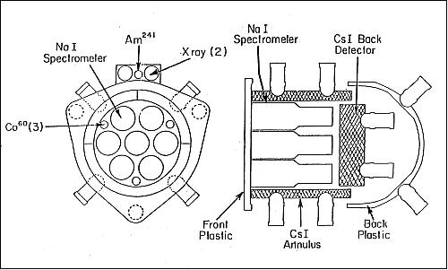
GRS is a collaborative effort between the University of New Hampshire, the Max Planck Institute in Garching, Germany, and the Naval Research Laboratory (NRL), Washington DC. The instrument includes seven integral-line calibrated NaI(Tl) detectors for nuclear lines between 0.3 and 0.9 MeV (7 gain-controlled detectors 7.6 cm diameter x 7.6 cm thick). The energy resolution (FWHM - full width at half maximum) of these detectors is > 7% at 0.662 MeV. In addition, a thick CsI(Na) crystal, along with the NaI(Tl) spectrometers, is sensitive to gamma-rays in the range 10-140 MeV and to neutrons with energies above 20 MeV. An auxiliary system of two NaI detectors yields hard X-ray fluxes from 10 to 140 keV. Time resolutions are typically about 2 s and 16 s, but can be as fine as 64 ms for the 300-350 keV energy band.
Prior to SMM only a handful of solar flares had been observed in the gamma-ray region. Based on these early data, the consensus was that flare acceleration took place in two phases. The first phase was thought to accelerate electrons to energies of ~ 100 keV in about 1 s. The second phase, which was thought to occur only in large flares, was thought to be the Fermi accelerations of ions and electrons to very high energies on a timescale of minutes. 20)
Among other things, GRS made important contributions to the international study of Supernova 87A, which in Feb. 1987 provided astronomers with their first local opportunity since 1604 to study such an explosion.
HXRBS (Hard X-Ray Burst Spectrometer)
HXRBS instrument PI: B. R. Dennis, GSFC. The primary objective of HXRBS was to study hard X-ray spectra of solar flares on time scales as short as 10 ms.
• to determine the nature of the mechanisms which accelerate electrons to 20-200 keV in the first stage of the solar flare, and to >1 MeV in the second stage of many flares
• to characterize the spatial and temporal relation between electron acceleration, storage and energy loss throughout the solar flare.
The instrument is a collimated X-ray spectrometer. The detector consists of two primary scintillation crystal components. Scintillation events in its actively collimated CsI(Na) detector are read out every 128 ms in fifteen energy channels between ~25 to ~500 keV. A circulating memory is able to accumulate relatively brief periods of data during the more intense flares with time resolution down to 1 ms. The full width at half maximum field of view is ~40º. Since the SMM views the Earth during the nighttime portion of each orbit, only about 1 event on 40 is detected with a pi/6 sr field of view for which the spectra are not badly contaminated by the shield-processed contributions. Between launch and mid-1985, more than 15 gamma-ray bursts were seen by the HXRBS. 21) 22)
HXIS (Hard X-Ray Imaging Spectrometer)
HXIS instrument PI: C. de Jager, Astronomical Institute, Utrecht, NL, and University of Birmingham, UK. Objective: study of the energy problem associated with hard X-ray generating electrons. Study of flare models and mechanisms. The instrument consists of an imaging collimator of ten grid plates, each divided into 576 sections, and a position-sensitive detector system consisting of 900 mini-proportional counters. The grids form a coarse FOV 6.35 arcmin in extent and a fine field of view 2.67 arcmin across (with 8 arcsec square pixels). Each pixel is sampled in six energy bands ranging from 3.5 to 30 keV, with time resolution down to 1.25 s. 23)
HXIS served as “flare alarm” to alert the other instruments electronically. Note: HXIS malfunctioned in June 1981 and could not be repaired in the SMM rescue mission in April 1984.
The 1980 HXIS data set, however, forms a most impressive record of the spatial and energetic distribution of X-rays in solar flares, with a spatial resolution never before achieved at such high energies. The data from HXIS consist of solar flare images in X-rays, built up from simultaneous photon counting rates in each of 6 energy bands with boundaries at 3.5, 5.5, 8.0, 11.5, 16, 22, and 30 keV, from each of 432 contiguous square regions of the sun.
UVSP (Ultraviolet Spectrometer and Polarimeter)
UVSP instrument PI: E. Tandberg-Hanssen, NASA/MSFC. Objective: Study of UV radiation from the solar atmosphere, in particular from the active regions, flares, prominences, and the active corona. UVSP consists of an aplanatic Gregorian telescope of about 2” resolution, an Ebert-Fastie spectrometer, and five photomultiplier detectors. The telescope secondary is mounted on gimbals and may be rastered to build up an image of an area on the sun of up to 256 x 256 arcsec, in steps of as little as 1 arcsec. The entrance apertures range in size from 1 x 1 arcsec to 15 arcsec x 286 arcsec, and the exit slits range from 0.1 to 3.0 Å in second order. 24)
A polarimeter may be inserted behind the exit aperture; it consists of two systems: a three-quarter wave retarder for those wavelengths where the spectrograph grating is an effective linear polarizer, and a quarter-wave retarder and linear polarizer for use at wavelengths at which the grating polarization is very low. The instrument is sensitive to wavelengths of 1170 - 1800 Å in second order and up to 3600 Å in first order.
In April 1985, the UVSP grating drive mechanism became stuck; the grating appeared to be fixed at a wavelength of about 1380 Å (second order; about 2760 Å in first order). During periods of solar activity, UVSP is used in second order to provide pointing and timing information for other SMM instruments; at other times, first order measurements of ozone concentration in the Earth's atmosphere are carried out at S/C sunrise and sunset (occultation measurements). These unique observations make possible a mapping of ozone concentrations at latitudes of ±50º at altitudes of 50 - 75 km. Approximately 20,000 separate ozone altitude profiles were obtained from late 1985 through March 1989. 25)
XRP (Soft X-Ray Polychromator)
XRP instrument PIs: J. L. Culhane, U. College, London; K. J. H. Phillips, RAL (Rutherford Appleton Laboratory), UK; K. T. Strong, Lockheed, Palo Alto, CA. Objective: investigation of those aspects of solar activity that lead to the production of plasma temperatures in the 1.5 to 50 million degree range. 26) 27)
The XRP consists of two distinct instruments, the BCS (Bent-Crystal Spectrometer), PI: J. L. Culhane and FCS (Flat-Crystal Spectrometer). The FCS is able to rotate its crystals to provide its seven detectors with access to the spectral range 1.40-22.43 Å. The BCS, with a collimator field of view of 6 arcsec, is able to obtain spectra in the range 2-3 Å, at a resolving power λ/Δλ of ≈104 with eight position-sensitive proportional counters.
References
1) S. P. Maran, B. E. Woodgate, “A Second Chance for Solar Max,” Sky & Telescope, June 1984, pp. 498-500
2) A. Chaikin, “Solar Max: Back from the Edge,” Sky & Telescope, June 1984, pp. 494-497
3) http://solarscience.msfc.nasa.gov/SMM.shtml
4) http://heasarc.gsfc.nasa.gov/docs/heasarc/missions/solarmax.html#overview
5) J. D. Bohlin, K. J. Frost, P. T. Burr, A. K. Guha, G. L. Withbroe, “Solar Maximum Mission,” Solar Physics, Vol. 65, No 1, Feb. 1980, pp. 5-14
6) “NASA's Solar Maximum Mission: A Look at the New Sun,” June 1987, NASA brochure, edited by J. B. Gurman
7) “The Solar Maximum Mission Experiments,” Solar Physics, Volume 65, pp. 5-109
8) http://www.solarviews.com/eng/solmax.htm
9) http://nssdc.gsfc.nasa.gov/nmc/spacecraftDisplay.do?id=1980-014A
10) Chris St.Cyr, Joan Burkepile, “Solar Maximum Mission Overview,” URL: http://smm.hao.ucar.edu/smm/smm_mission.html
11) http://heasarc.gsfc.nasa.gov/docs/heasarc/missions/solarmax.html
12) http://umbra.nascom.nasa.gov/smm/
13) R. C. Willson, S. Gulkis, M. Janssen, S. H. Hudson, G. A. Chapman, “Observations of Solar Irradiance Variability,” Science, Volume 211, Feb. 1981, pp. 700-702
14) R. C. Willson, “Measurements of Solar Total Irradiance and Its Variability,” Space Science Reviews, Vol. 38, 1984, pp. 203-241.
15) http://badc.nerc.ac.uk/data/gedex/detail/smmacrim.det
16) R. C. Willson, “ Solar Total Irradiance Observations by Active Cavity Radiometers,” Solar Physics, Vol. 74, 1981, p. 218
17) http://acrim.jpl.nasa.gov/mission/mission_cavity.html
18) “Coronal Mass Ejections from the Solar Maximum Mission,” URL: http://smm.hao.ucar.edu/smm/smmcp_cme.html
19) Chris St.Cyr, Joan Burkepile, “Solar Maximum Mission Coronagraph / Polarimeter Instrument Description,” http://smm.hao.ucar.edu/smm/smmcp_info.html
20) “The Gamma-ray Spectrometer Experiment on the Solar Maximum Mission Satellite,” Satellite Final Report, 14 Oct.. 1984 - 15 April 1986, University of New Hampshire, URL: http://ntrs.nasa.gov/archive/nasa/casi.ntrs.nasa.gov/19870003961_1987003961.pdf
21) L. E. Orwig, K. J. Frost, B. R. Dennis, “The Hard X-Ray Burst Spectrometer on the Solar Maximum Mission,” Solar Physics., Vol. 65, Feb. 1980, pp. 25-37
22) L. G. Workman, J. L. Wolfgang, “Design and performance of the solar maximum mission Hard X-ray Burst Spectrometer,” American Institute of Aeronautics and Astronautics, 19th Aerospace Sciences Meeting,, St. Louis, MO, USA, Jan 12-15, 1981, AIAA-1981-205
23) H. F. Van Beek, P. Hoyng, B. Lafleur, G. M. Simnett, “The Hard X-ray Imaging Spectrometer (HXIS),” Solar Physics, Vol. 65, No 1, Feb. 1980, pp. 39-52
24) B. E. Woodgate, E. A. Tandberg-Hanssen, E. C. Bruner, J. M. Beckers, J. C. Brandt, W. Henze, C. L. Hyder, M. W. Kalet, P. J. Kenny, E. D. Knox, A. G. Michalitsianos, R. Rehse, R. A. Shine, H. D. Tinsley, “ The Ultraviolet Spectrometer and Polarimeter on the Solar Maximum Mission,” Solar Physics, Vol. 65, No 1, Feb. 1980, pp. 73-90
25) A. C. Aikin, W. Henze, D. J. Kendig, R. Nakatsuka, H. J. P. Smith, “Variations of Mesospheric Equatorial Ozone as observed by the Solar Maximum Mission,” Geophysical Research Letters, Vol. 17, No. 3, March 1990, pp. 299-300
26) L. W. Acton, J. L. Culhane, A. H. Gabriel, R. D. Bentley, J. A. Bowles, J. G. Firth, M. L. Finch, C. W. Gilbreth, P. Guttridge, R. W. Hayes, E. G. Joki, B. B. Jones, B. J. Kent, J. W. Leibacher, R. A. Nobles, T. J. Patrick, K. J. H. Phillips, C. G. Rapley, P. H. Sheather, J. C. Sherman, J. P. Stark, L. A. Springer, R. F. Turner, C. J. Wolfson, “ The soft X-ray polychromator for the Solar Maximum Mission,” Solar Physics, Vol. 65, No 1, Feb. 1980, pp.53-71
27) Ken Phillips, “Solar Maximum Mission,” URL: http://www.sstd.rl.ac.uk/project/smm/
The information compiled and edited in this article was provided by Herbert J. Kramer from his documentation of: ”Observation of the Earth and Its Environment: Survey of Missions and Sensors” (Springer Verlag) as well as many other sources after the publication of the 4th edition in 2002. - Comments and corrections to this article are always welcome for further updates (eoportal@symbios.space).