SLATS (Super Low Altitude Test Satellite) / Tsubame
Non-EO
JAXA
Quick facts
Overview
| Mission type | Non-EO |
| Agency | JAXA |
| Launch date | 23 Dec 2017 |
SLATS (Super Low Altitude Test Satellite) / Tsubame
Spacecraft Launch Mission Status Sensor Complement References
Overview
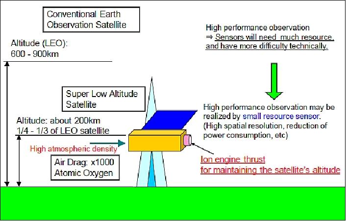
SLATS is a technology demonstration minisatellite of JAXA to orbit the Earth at an altitudes in the range of 180-250 km. Its main objectives are to understand the effects of high-density atomic oxygen on the satellite and to verify the possibility of orbit control using an ion engine system. In this mission, an ion engine system is used to compensate for air drag, which cannot be neglected in such a low Earth orbit. 1) 2) 3) 4) 5) 6) 7)
The Tsubame nickname of the mission, meaning swallow, was chosen by JAXA in 2014 in a public renaming campaign.
Specific goals of the mission are:
1) Verification of super low altitude satellite system
2) Measurement of atmospheric density in super low altitude
3) On-orbit monitoring of atomic oxygen to understand the effects of high-density atomic oxygen on the satellite.
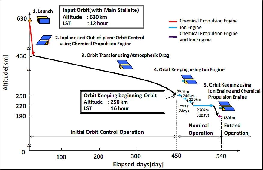
SLATS is planned to be launched as a secondary payload on the ALOS-2 mission in 2013/14 on the H-IIA vehicle. Hence, the microsatellite will be deployed into a sun-synchronous orbit of ~630 km altitude, inclination = 97.9º, the LSDN (Local Sun time on Descending Node) is 12:00 hours ± 15 min.
In the IOC (Initial Orbit Control) operation period, SLATS will reach the 250 km altitude and LSDN of 16:00 hours orbit using its own chemical propulsion system (RCS). At this level and below, the ion engine is used to compensate for the atmospheric drag. A long duration operation of the ion engine is needed.
Orbit | Initial: 628 km, circular orbit, LSDN = 12:00 hours | |
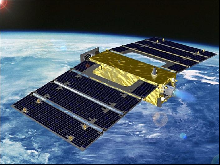
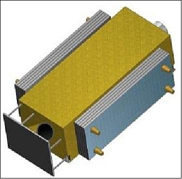
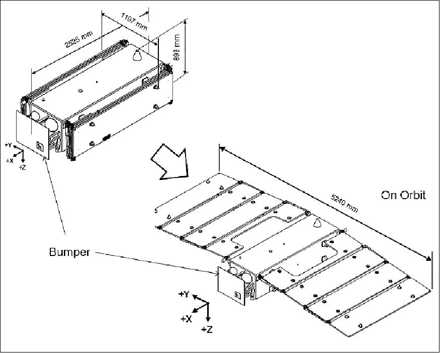
Minisatellite mass, size | 383 kg, 2.5 m x 5.2 m x 0.9 m (deployed) | |
Mission life | ~2 years or longer | |
Electric power consumption | ~700 W (max) | |
Sensor complement | AOFS (Atomic Oxygen Fluence Sensor) | |
Ion engine | Thrust: 10-28 mN (1 engine) | |
Chemical propulsion engine | Thrust: 1 N x 4 engines | |
In mid-2012, SLATS is in the critical design phase. The project is developing a new ion engine system for the SLATS and the practical satellites to follow based on the ETS-VIII/Kiku-8 ion engine system.
Verification of super low altitude satellite system
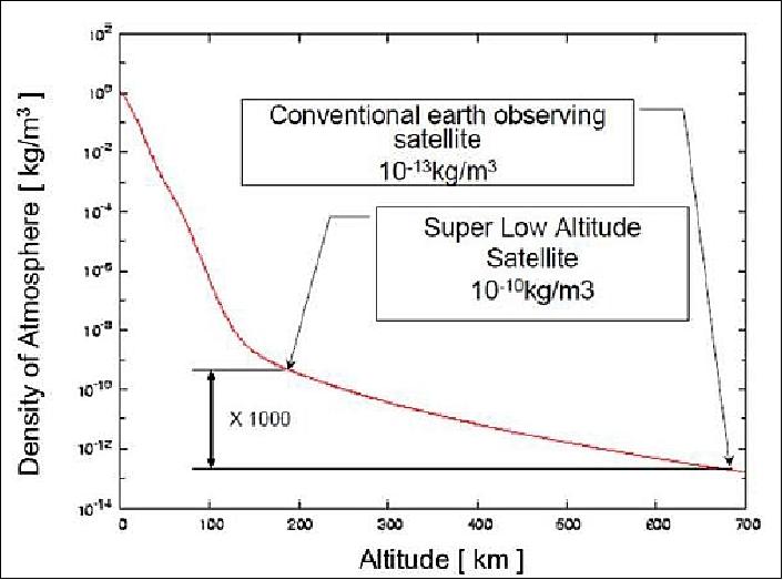
In the super low altitude orbit, ~200 km high, atmospheric density is too high to keep satellite's altitude by high air drag. Figure 4 shows the relation between the altitude and the air density. By the study of the air drag for the super low altitude satellite, it is found that the satellite's aerodynamic shape and the particular attitude direction to the velocity vector is an important factor for drag compensation. In order to observe the Earth continuously at super low altitude orbit, it is necessary to cancel the air drag to maintain the satellite's altitude.
The SLATS project will conduct on-orbit engineering tests regarding the orbit and altitude control of the spacecraft with the ion engine system as shown in Figure 5.
Measurement of atmospheric density in super low altitude
There is a need for air density measurements in the altitude range of ~200 km. Currently, applicable data is estimated by using an air density model based on actual measurement in nominal LEO (Low Earth Orbit), higher than about 400 km and on the ground. In the aerodynamic design of SLATS, the project takes account of the worst case in estimated data. Actual measurements of atmospheric density data will be acquired to be correlated with AOCS and GPS receiver data to study the effect caused by atmospheric density.
Monitoring on-orbit atomic oxygen data
Since the atmosphere in the altitude range of 180-200 km contains a lot of atomic oxygen (AO), it can deteriorate the materials of a satellite and may cause some unexpected issues. Hence, actual AO density data measurements in the super low altitude range is also a very desirable parameter next to that of atmospheric density data. The project requirements call for the degradation monitoring of material samples (surface change) in the super low altitude environment.
Spacecraft
The SLATS microsatellite is intended to be a precursor mission to follow-on operational super low altitude satellites. 8)
NSTT (Next-generation Star Tracker)
JAXA in collaboration with NEC Toshiba Space Systems is developing NSTT to provide high-accuracy attitude determination results: the random error is < 4 arcsec (3σ), while the bias error is < 6 and 4 arcsec (3σ), respectively, for wide and narrow temperature ranges. NSTT is able to track and acquire stars under high attitude-rate of 2º/s with 99.9% probability. A demonstration/qualification flight of NSTT is scheduled for SLATS. 9)
Parameter | Performance specification | |
Attitude accuracy | Cross boresight axis | < 4 arcsec (3σ, angular rate is < 0.3º/s) |
Boresight axis | < 40 arcsec (3σ, angular rate is < 0.3º/s) | |
Attitude accuracy (bias) | Cross boresight axis | < 6 arcsec (3σ, accuracy is defined within operation temperature) |
Boresight axis | < 20 arcsec (3σ, accuracy is defined within operation temperature) | |
Max acquisition rate | > 3º/s (99.9% of the whole celestial sphere) | |
FOV (Field of View) | 16º x 16º | |
Output rate | 4 Hz | |
Sun avoidance angle | 25º | |
Maximum power consumption | < 20 W | |
Instrument mass | < 6.2 kg | |
Vibration tolerance | > 20 G rms | |
Shock tolerance | > 1000 G srs | |
Operation temperature | -25º to 55ºC | |
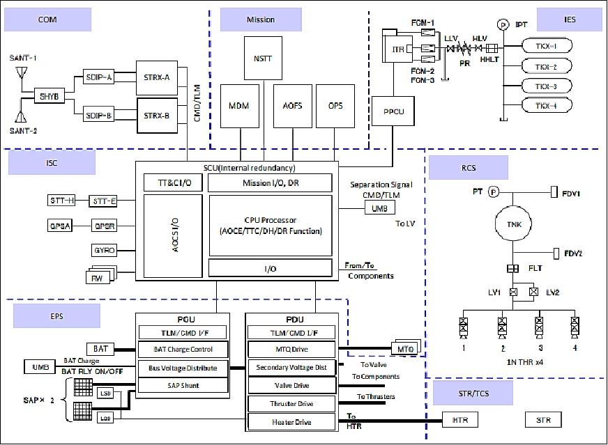
IES (Ion Engine System)
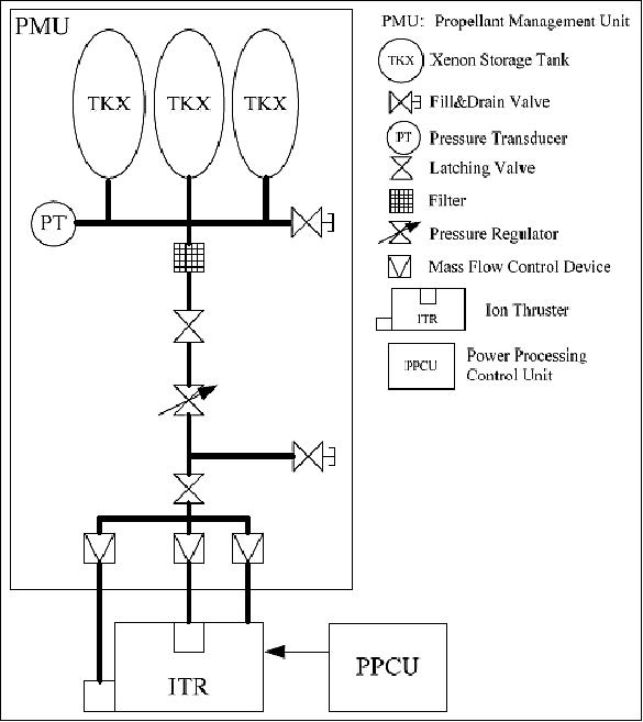
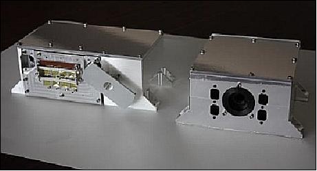
The IES consists of a PMU (Propellant Management Unit), an ion thruster and a PPCU (Power Processing Control Unit), including an Ion thruster controller. The PMU supplies xenon gas to the ion thruster. The PPCU supplies electrical power to the ion thruster according to on-board control sequence. The ion thruster generates ion beam and thrust. 10)
The PMU is almost the same unit as used in the ETS-VIII (Kiku-8) propellant management system. Xenon is used as propellant and is stored in three tanks at a pressure of approximately 7MPa. The xenon mass flow rate into the thruster is controlled properly through a high-pressure latching valve, a regulator, a low-pressure latching valve and mass flow control devices. The mass flow control device is a fixed orifice and the mass flow rate is determined only based on the upstream pressure. The mass flow rate is adjusted at 10.5 cm3/s (including 2 cm3/s for the neutralizer).
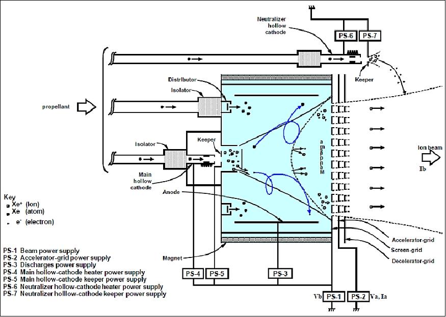
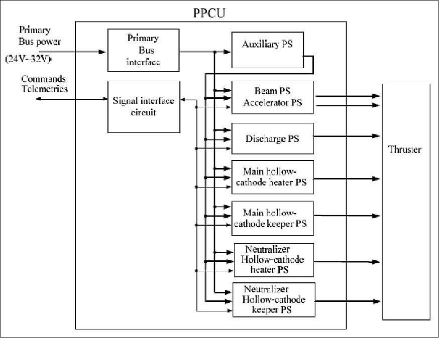
The PPCU, developed at MELCO and JAXA, is a new 20 mN class ion engine system used for air drag compensation on the spacecraft. The PPCU consists of seven power supplies (PS-1~PS-7) for an ion thruster, an auxiliary power converter, a primary bus interface, and a signal interface circuit. The Kiku-8 ion thruster has the lifetime of 16,000 hours at 20mN; hence, the lifetime satisfies the SLATS requirement. 11) 12) 13) 14)
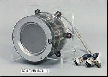
The ion engine (Figure 8) produces thrust through the reaction force obtained when ions accelerated by an electrical force are expelled. It consists of an "ion generator" (generates ions from a propellant such as xenon), an "ion acceleration system" (accelerates those ions), a "neutralizer" (emits electrons for neutralizing the ions expelled into space), seven "power sources" (operate the above three sections), and a "controller" (controls the power sources).
The electrical interface with the satellite system has been changed from the Kiku-8 system. The primary input voltage of the Kiku-8 PPU is 100 V. On the other hand, the SLATS PPCU is designed to work under an input voltage between 24 V and 32 V. The control algorithm is different from that of the Kiku-8 IES. The SLATS keeps its altitude by thrust on/off control. The on/off command must be given to the PPCU autonomously as the contact time from a ground station is very short. The thrust is automatically generated or stopped using orbit data gained by an on-board GPS receiver.
The signal interface circuit is connected to the satellite data bus and contains the operation modes. The ORBIT mode is used in the altitude keeping operation of SLATS. The control logic of the operation modes are installed in FPGAs. PS-1 and PS-2 use the same high-voltage transformer to synchronize their output voltage. Their power efficiency of 90 % is required.
Mode | Operation |
IDLG | Neutralizer and main hollow-cathode heating (PS-4 and PS-6 on, low level) |
ACTV_N | Neutralizer hollow-cathode activation (PS-6 on, high level) |
ACTV_M | Main hollow-cathode activation (PS-4 on, high level) |
NEUT | Neutralizer discharge on (PS-7 on) |
DISC | Main hollow-cathode discharge and main discharge on (PS-5 and PS-3 on) |
ORBIT | All discharge on and beam on/off by command from orbit control system (PS-3, PS-5 and PS-7 on and PS-1 on/off by command) |
CM | Grid cleaning, short-circuit opening (function for failure) |
Power Supply | Name | Voltage range (V) | Current range (A) | Ripple (%) P.P. | Regulation (%) C.V (constant current) | Maximum Power (W) |
PS-1 | Beam PS | 800~1,100 | 0.2~0.6 | 5 | C.V ±3 | 660 |
PS-2 | Accelerator PS | 400~500 | 0.001~0.1 | 5 | C.V ±5 | 5.5 |
PS-3 | Discharge PS | 45 | 1.5~3.5 | 5 | C.V ±5 | 140 |
PS-4 | Main hollow cathode heater PS | 15 | 1.4~4.0 | 5 | C.C ±3 | 60 |
PS-5 | Main hollow cathode keeper PS | 15 | 0.5 | 5 | C.C ±5 | 7.5 |
PS-6 | Neutralization hollow cathode heater PS | 15 | 1.4~4.0 | 5 | C.C ±3 | 60 |
PS-7 | Neutralization hollow cathode keeper PS | 30 | 0.5 | 5 | C.C ±5 | 15 |
Engine type | Kaufman |
Propellant | Xenon |
Thrust | 11.5~17mN |
Mass flow rate | 10.5 cm3/s |
Instrument mass, primary voltage | 43 kg, 24-32 V |
Power consumption | <403 W @ 11.5 mN, <580W @ 17 mN |
Signal interface | RS422 |
Propellant mass | 12 kg |
MEOP | 15 MPa (LBB designed tank) |
Proof pressure | >1.5 x MEOP (LBB designed tank) |
Burst pressure | 2.0(tank), 2.5(valve), 4.0(tube etc.) x MEOP (LBB designed tank) |
Leakage | internal: <0.5 Pa m3/h(Ghe), external: <1x10⁻⁷ Pa m3/s(Ghe) |
Launch
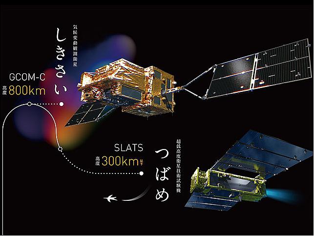
The demonstration/qualification flight of SLATS / Tsubame was launched as a secondary payload on 23 December 2017 (10:26:22 JST, 01:26:22 UTC) from TNSC (Tanegashima Space Center), Japan. The primary payload on this flight was the GCOM-C1 spacecraft of JAXA. The launch provider was Mitsubishi Heavy Industries, Ltd. (upgraded H-IIA launch vehicle). 15) 16) 17)
The H-IIA launch vehicle No. 37 incorporates JAXA's newly developed technology to insert GCOM-C1/Shikisai and SLATS/Tsubame into different orbital altitudes, respectively. It will expand opportunities of multiple satellite launch and take full advantage of the capability of H-IIA.
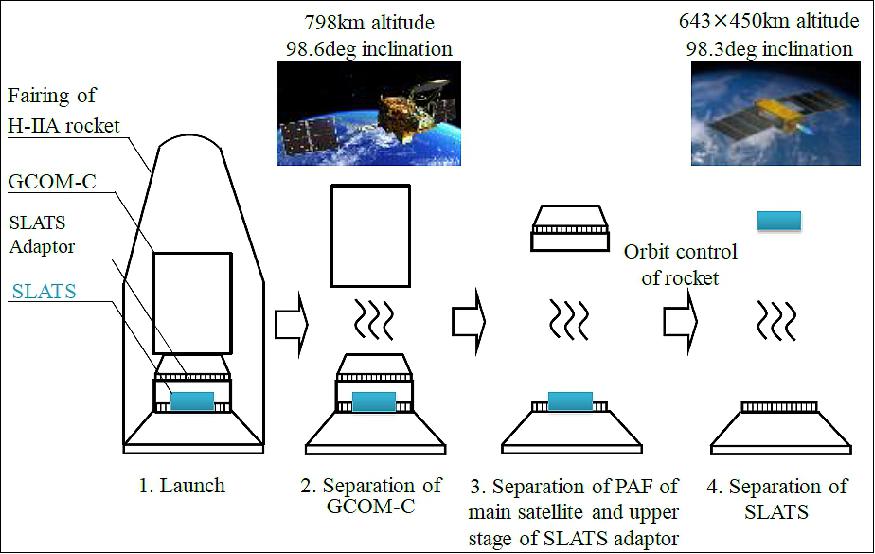
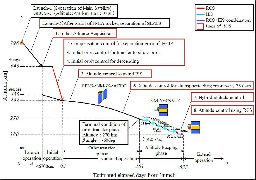
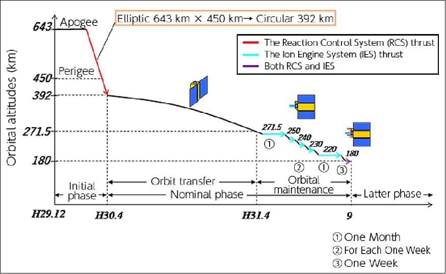
Launch operation sequence: Figure 12 shows the launch sequence. First, GCOM-C was released into 798 km altitude and 98.6º inclination, LST10:30 of SSO (LST =Local Sun Time of descending node). Second, the upper stage of the SLATS adapter was released. Third, the altitude and inclination were controlled by injections of H-IIA Launch Vehicle second stage engine. Finally, SLATS was released into 643 x 450 km altitude and 98.3º inclination, LST10:30 of the elliptical orbit. SLATS had to be released at such a high altitude elliptical orbit due to the GCOM-C orbit and the orbit control performance of H-IIA Launch Vehicle. It took less than 6,700 seconds to release SLATS from the launch vehicle. 18)
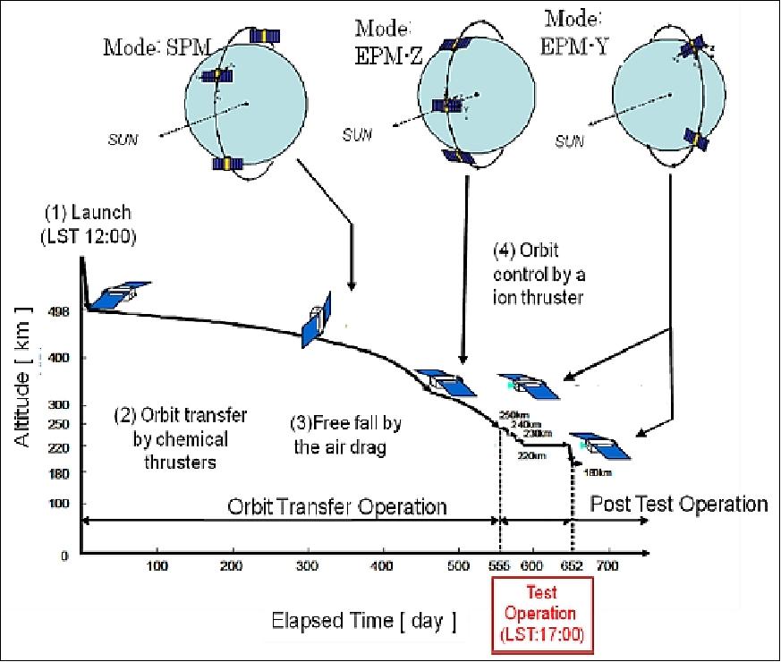
Initial operation: After SLATS was separated from the launch vehicle, SLATS performed the rate damping, the three-axis determination, the sun acquisition and the deployment of solar panels. After that, SLATS checked its own housekeeping devices and began the operation of all mission sensors. After checking all devices, SLATS transferred to a circular orbit and descended to an altitude of 393 km using its chemical RCS (Reaction Control System). This control term is called "initial orbit control". In this phase, the nominal attitude mode is SPM (Sun Pointing Mode). When conducting optical observation and the thrust of RCS, SLATS used NM-Z attitude mode.
Orbit
Initial sun-synchronous elliptical orbit, altitude 643 x 450 km, inclination of 98.3º.
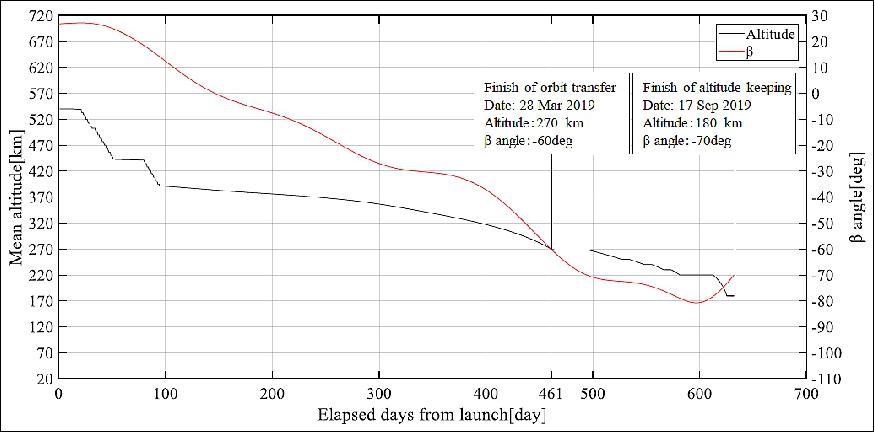
Orbit transfer phase: In this phase, SLATS reaches 270 km altitude and -60º β angle at the same time using atmospheric drag, the RCS and geopotential perturbations. The -60º β angle is required for the solar power generation of the ion engine in the next orbit keeping phase (the solar power generation is proportional to sin|β|). The change of the β angle consists mostly of the long-term change of right ascension of the ascending node by geopotential (dΩ/dt).
The period of this phase can be shortened by increase of the inclination (increase of dΩ/dt). However, the inclination of H-IIA Launch Vehicle was changed from 98.6º for GCOM-C to 98.3º in the launch phase. Because the β angle of orbit keeping phase has to be smaller than -60º to restrict electricity consumption of the ion engine. Figure14 shows the β angle begins to increase after about -80º when the orbit plane and the sun direction cross at right angle. Because the β angle is also changed by the north-south moving of the sun, this timing doesn't correspond to the -90º β angle strictly. If the inclination is bigger than 98.3º,the β angle is bigger than -60º before finishing of 180 km altitude keeping, therefore, SLATS begins to descend from 393 km altitude and 98.3º inclination orbit gradually.
The altitude history of this phase is called NDO (Nominal Descending Orbit). NDO is defined before launch and is updated based on the practical separation orbit after the launch. SLATS flies along this altitude history using the atmospheric drag of SPM attitude mode mainly. The design of NDO uses NRLMSISE-00 atmospheric model, 19) Marshall solar activity future estimation model as the solar and geomagnetic activity future prediction model and SLATS atmospheric drag model.
In the case that SLATS doesn't reach to β angle -60º at 268 km altitude, it's impossible to use the ion engine and the altitude keeping mission is put on hold. Therefore, SLATS tracks NDO using the aero attitude control mode and the RCS. This operation is called "NDO tracking".
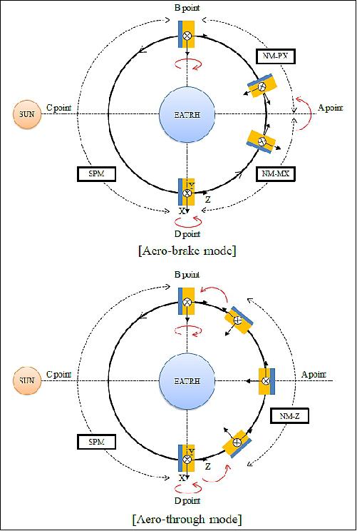
SLATS has the aero attitude control mode which is divided into "Aero-braking mode" and "Aero-through mode". Figure 15 shows the sequence of attitude change of the both aero attitude control mode in the one cycle. Aero-braking mode is to maximize the atmospheric drag. In this mode, SLATS uses the NM-PX or the NM-MX attitude mode and maintains its attitude that the solar array panel faces to the satellite flight direction in the shadow. On the contrary, the Aero-through mode is to minimize the atmospheric drag. In this mode, SLATS uses the NM-Z attitude mode and maintains its attitude that the edge plane of its solar array panel faces to the satellite flight direction in the shadow. Although the constant use of NM-PX/NM-MZ or NM-Z in the one cycle maximizes the effect of drag control, these attitude modes can't generate enough solar power. Therefore, SLATS uses these attitude modes only in the shadow. The duration of these attitude modes is about 40% of the orbital period.
SLATS tracks NDO mainly using the aero attitude control mode and it uses the RCS secondarily at the end of every month. SLATS has only 34.3 kg of the RCS fuel, but SLATS uses the RCS in many scenes (Figure 13). Consequently, saving the fuel of RCS is very important for the mission success of SLATS.
In this phase, because SLATS descends from 393 km to 270 km altitude, there is a possibility of passing through ISS orbital altitude. To avoid the collision, the unified flight dynamics system (uFDS) of SLATS analyses the interference between SLATS and ISS every day. If the interference is expected, SLATS will avoid the ISS orbit actively.
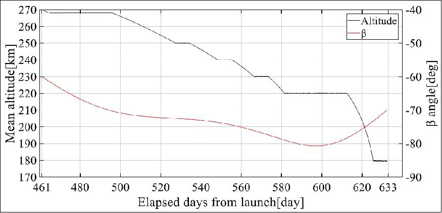
Altitude keeping phase: This phase operates the altitude keeping which is the main mission of SLATS. In this phase, SLATS keeps 268 and 220 km altitude for more than 31days, respectively, and 250, 240, 230, 220 and 180 km altitude for more than 7 days, respectively. SLATS uses the IES (Ion Engine System) above 220 km altitude. Because the atmospheric drag at 180 km altitude is expected to be very high, SLATS uses the IES and the RCS at the same time. The attitude of this phase is basically NM-Y for solar power generation. Available time of the IES has been decided at each keeping altitude according to the β angle because the electrical consumption of IES accounts for about half of total consumption of SLATS. Table 6 shows the use ratio of IES at each keeping altitude, and SLATS only uses the IES for the time which multiply this value by the cycle period in the one cycle. The target accuracy of altitude control is ±1km (1σ) at each altitude. The thrust time of RCS is about 80 sec in the one cycle and is decided by the altitude keeping analysis in order to satisfy the accuracy of altitude control (Table 6). Figure 16 shows the result of keeping altitude analysis.
Keeping altitude ([km) | 268 | 250 | 240 | 230 | 220 | 180 |
Maximum β angle (º) | -62 | -73 | -74 | -76 | -78 | -70 |
Use ratio of IES (-) | 0.3 | 1.0 | 1.0 | 1.0 | 1.0 | 0.6 |
Altitude error (m) µ σ | 9.75 | 66.0 | 70.6 | 52.8 | 66.7 | -315 |
30.3 | 67.6 | 64.1 | 59.6 | 91.5 | 226 | |
where µ is the average of altitude error which means altitude minus required keeping altitude | ||||||
SLATS judges whether to use the IES (Ion Engine System) and/or the RCS (Reaction Control System) in the cycle at descending node automatically. If the cycle period measured by on-board GPS is lower than the objective value uploaded every keeping altitude, SLATS uses the IES and/or the RCS in the cycle. The keeping altitude is changed by uploading the next objective cycle period. Furthermore, this value is defined for the IES and the RCS independently. The value of RCS is smaller than the IES. Therefore, if the thrust of IES can't exceed an atmospheric drag, the RCS is used automatically. This setting is the core of the hybrid altitude control. The both engines are injected in the regions which have the north or south pole in the center for keeping the circle orbit. The period from launch to finish of 180 km altitude keeping is estimated to be about 633 days.
Mission status
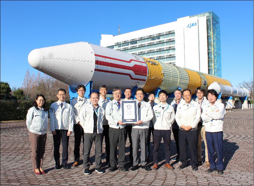
- December 24, 2019: JAXA (Japan Aerospace Exploration Agency) announced that its Super Low Altitude Test Satellite "TSUBAME" (SLATS) was registered by the Guinness World Records as having achieved the "lowest altitude by an Earth observation satellite in orbit." 20)
Note: Guinness World Records is a registered trademark by Guinness World Records Limited.
1) Details on the Guinness World Record set by the Super Low Altitude Test Satellite "TSUBAME" (SLATS): 21)
- The lowest altitude by an Earth observation satellite in orbit is 167.4 km (104 mi) and was achieved by JAXA's TSUBAME (JAPAN) during its mission from 23 December 2017 to 1 October 2019.
- TSUBAME was a Super Low Altitude Test Satellite operated by JAXA. With its ion engine, TSUBAME was able to capture high-resolution satellite images despite the atmospheric drag and density of atomic oxygen present in super low altitudes. It maintained seven different orbital altitudes, with 167.4 km being the lowest. At 167.4 km altitude, TSUBAME used both its ion engine system and gas-jet thrusters.
2) Achievements made by "TSUBAME" (SLATS) and future prospects: A super low altitude satellite has the merit of being able to take high resolution satellite images using a small sensor. However, when in orbit at an altitude that is categorized as being super low—at an altitude between 200 km and 300 km—the satellite will be exposed to 1,000 times more atmospheric resistance and concentrated atomic oxygen that would cause it to deteriorate as compared to other Earth observation satellites orbiting at the usual altitudes. Thus, super low altitude has been considered as being unsuitable for Earth observation satellites that require precise positioning, orbit control and long-term satellite operations.
- "TSUBAME" first maintained an orbital altitude of 271.5 km, which was gradually lowered to finally reach the 167.4 km altitude that was recognized as a world record this time by the Guinness World Records. This orbit in super low altitude was maintained for a period of seven days. During its time orbiting in the record-breaking altitude, "TSUBAME" conducted tests on taking high resolution satellite images, and succeeded in obtaining good results. The test satellite also succeeded in acquiring data of atmospheric density, atomic oxygen density, and the level of deterioration of material samples that were exposed to the atmosphere. Furthermore, the satellite also succeeded in demonstrating that the material developed by JAXA has the ability to withstand exposure to atomic oxygen for a long period of time.
- JAXA will make use of the information acquired through "TSUBAME" to achieve further utilization of space for the future in order to help achieve scientific and technological growth and contribute toward resolving social issues in Japan.
Comment from Masanori SASAKI, SLATS Project Manager: "I think we managed to create this unprecedented satellite that is able to maintain orbit in super low altitude, not only because of the systematic and fundamental technologies that we possess to develop and operate artificial satellites, including our many years of experience of the ion engine and the tracking & control technologies, but also because of the high level of science and technology we have in Japan. I would like to make use of this achievement toward the future science, technology and satellite utilization, and contribute toward helping to solve as many of our social issues as possible."
- March 18, 2019: JAXA launched the SLATS (Super Low Altitude Test Satellite)/Tsubame mission, on December 23, 2017. The Tsubame satellite completed its orbit transfer phase and will transition on April 2 to the orbit keeping phase, powered by the ion engines. Designed to open up the possibilities of satellite use in a super low orbit, Tsubame gradually lowered its altitude using atmospheric drag and the onboard gas jet and has been in good health. 22)
- The ensuing orbit keeping operation executes the descent in five stages at altitudes of 271.5 km, 250 km, 240 km, 230 km, and 220 km. Each altitude is sustained for some time. In an orbit at 180 km, the target altitude, where there is significant atmospheric resistance, the gas jet is turned on in addition to the ion engines to withstand the drag. (See the images of the orbital maintenance operation profile).
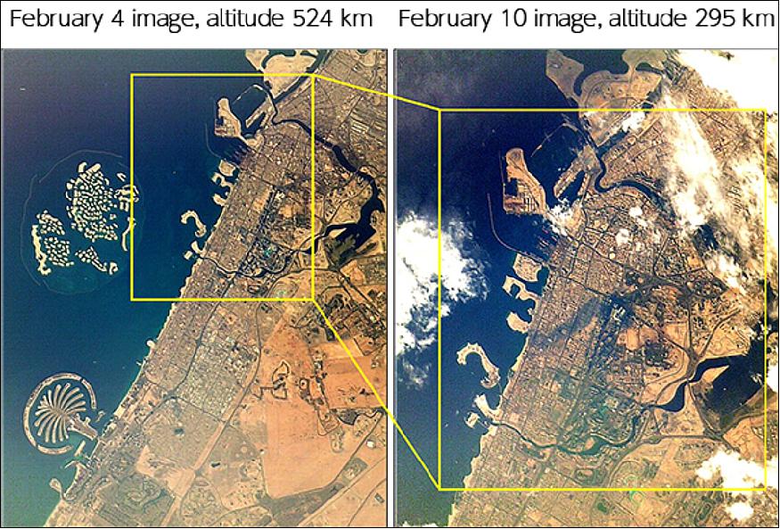
- From 2 April through 2 May, the Tsubame satellite will be sustained at 271.5 km, its recurrent orbit. Stationary measurments are scheduled every day of the month-long period above the Tokyo metropolitan area at high resolution, one advantage that satellite operation in a super low orbit affords. Thereafter, the satellite gradually lowers its altitude and enters the orbit keeping operation through September. During this operation, data is to be acquired of the atmosphere and atomic oxygen in a super low altitude. Photographing with the SHIROP (Small and High Resolution Optical Sensor) will also be experimented.
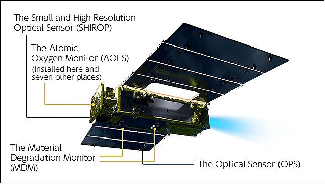
- SLATS/Tsubame's three onboard mission instruments are:
a) SHIROP (Small and High Resolution Optical Sensor)
b) OPS (Optical Sensor)
c) AMO (Atomic Oxygen Monitor) system – comprising of the Atomic Oxygen Fluence Sensor (AOFS) and the Material Degradation Monitor (MDM).
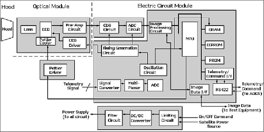
SHIROP
With a mass of 19.4 kg and a diameter of 20 cm, the SHIROP is a small optical sensor, providing a resolution of <10 m. It is designed to demonstrate observations at super low altitudes. Compared to 30 cm in diameter and 2.5 meter resolution of the Panchromatic Remote-sensing Instrument for Stereo Mapping (PRISM) onboard Daichi /ALOS (Advanced Land Observing Satellite), launched on January 24, 2006, the SHIROP is smaller and has a more sensitive resolution, as it observes in a super low orbit.
OPS
With a mass of 1.9 kg and a diameter of 2 cm, the instrument is used for wide-swath imaging. It returns 30 m resolution color images.
- October 2018: Results of SLATS operation (Ref. 18)
- Launch operation: SLATS was released according to the plan. The launch operation needed 6,480 seconds. Because errors of the separation orbit were very small, SLATS didn't compensate the separation errors of H-IIA (Figure 13).
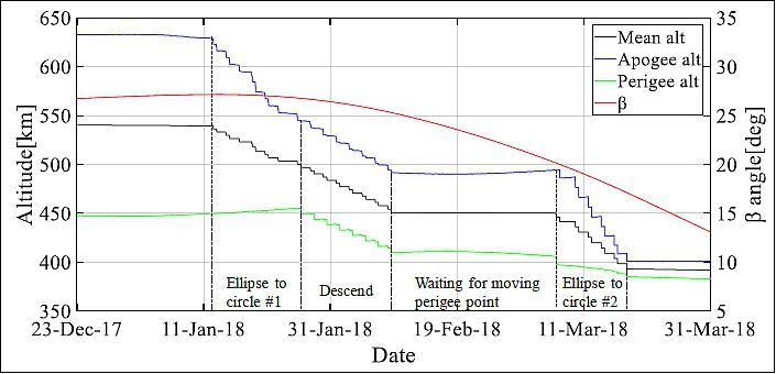
- Initial operation: SLATS used the RCS 40 times from 6 January to 18 March 2018 and transferred from a 643 x 450 km altitude elliptical orbit to 393 km altitude circular orbit. Furthermore, because SLATS descended below the altitude of the ISS, SLATS didn't need the altitude control to avoid the ISS (Figure 13).
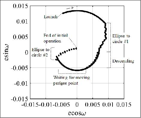
Figure 23 shows the history of the altitude and the β angle from launch to the end of initial operation (March 2018). Figure 23 indicates that SLATS stopped using the RCS from 9 February to 7 March, 2018. In this period, SLATS waited for the perigee point takes 15min away from the D point (Figure 15, at the D point, the angle between the vector from center of the earth to SLATS, and the vector from center of the Earth to the sun, is a right angle at the south pole side), because it can change SPM to NM-Z during the attitude mode only at the D point. If the perigee is close to the D point, SLATS can't take NM-Z attitude and can't use the RCS reversely at the perigee point. Therefore, SLATS divided the control for elliptical to circular into two phases. Figure 24 shows the eccentricity vector in the initial operation. As shown in this figure, SLATS could transfer to a frozen orbit at the end of initial operation.
- Nominal operation: SLATS is in the 'orbit transfer phase' at the end of August 2018 and is descending using the atmospheric drag and the RCS. At the end of August 2018, SLATS was at an altitude of 368 km. By the end of August, SLATS had used four times the RCS reversely for NDO tracking. Because the atmospheric drag which was estimated before launch is greater than the actual one.
Figure 25 shows the comparison of atmospheric density between the SLATS data calculated by the change of orbital period measured by the on-board GPS and the SLATS atmospheric drag model, and the atmospheric models which are NRLMSISE-00 (Ref. 19), JB2008, 23) DTM2013. 24) Figure 25 also shows: 1) The atmospheric density of NRLMSISE-00 has more than +20% bias compared with the other, 2) the value of JB2008 and DTM2013 correspond well on an average basis with the SLATS data. Because this trend has been going on throughout four months,the SLATS project decided to revise the NDO to cut off the future fuel of RCS.
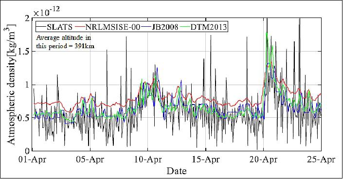
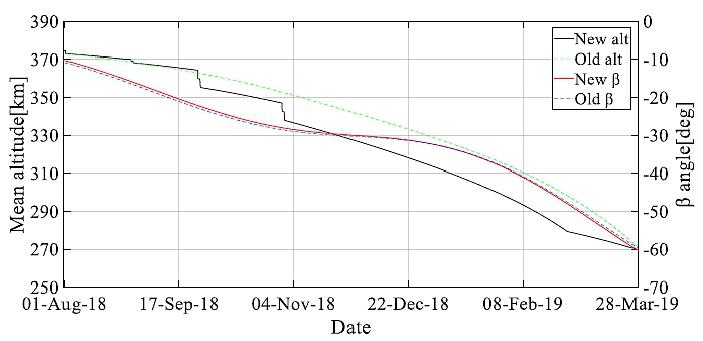
Figure 26 shows the altitude history of the new NDO. The descend rate of the new NDO is smaller than the old NDO by reducing the atmospheric drag estimation. In the new NDO, SLATS will use the RCS reversely at the end of September and October. After that, it is estimated that the orbit of SLATS adapts the new NDO without the RCS compensation.
- In summary, SLATS finished the launch operation and initial operation successfully and is descending toward the super low altitude. SLATS is in good condition and has the sufficient fuel of RCS. SLATS will be able to reach 270 km altitude at the end of March 2019. JAXA will continue to operate SLATS carefully for accomplishing its mission (Ref. 18).
- June 1, 2018: JAXA transitioned the phase of the Agency's SLATS mission from the initial operations to the orbit transfer. After the launch on December 23, 2017, SLATS completed its initial operations phase in March 2018.
Note: After the launch, performances and functions of the satellite were confirmed and using the onboard gas jet, the satellite's orbit was transferred from the insertion altitude by the launch vehicle to the orbital transfer altitude. 25)
- In the ongoing orbit transfer phase, the spacecraft is slowly descending its orbital altitude by the effect of atmospheric drag. At around the altitude of 380 km, SLATS is now continuing its nominal operations. Following are the three mission instruments that SLATS' observation operation is based on:
1) SHIROP (Small and High Resolution Optical Sensor)
2) OPS (Optical Sensor)
3) AMO (Atomic Oxygen Monitor System)
- SLATS continues lowering its altitude and is expected to reach its super low altitude at 268 km around April 2019. Thereafter, the onboard ion engine is used to provide the thrust to keep precisely the altitude.
- December 24, 2017: JAXA received telemetry data from GCOM-C1 /SHIKISAI and SLATS/TSUBAME, confirming that their satellite attitude control system had transitioned to the steady state. The current status of both satellites is stable. 26)
- Subsequently, the following procedure occurred – power generation that supports the satellites' operation by the deployed solar array wings, ground communications and sound attitude control that maintains those operations. Combined by the completion of the series of other operations, such as powering up of the bus and mission equipment, the satellites have entered the state where they can be sustained in orbit. This concludes their critical operations phase.
- SHIKISAI and TSUBAME will move on to the next operations phase, where the functions of the satellites' onboard apparatus will be examined approximately in the next three-month period.
- JAXA conveys deep appreciation for the support by all for the satellites' launch and tracking.
- December 23, 2017: Approximately at 12:54 p.m. (Japan Standard Time, JST), the JAXA Santiago Ground Station, Chile received the signals from TSUBAME/SLATS, launched from the JAXA Tanegashima Space Center earlier at 10:26:22 a.m. (JST), December 23, 2017. The signal reception confirms that the satellite's solar array deployment and attitude control based on the onboard sun sensors have occurred as scheduled. 27)
Sensor complement
The super-low altitude of SLATS requires to observe the material response in the surrounding environment of simultaneous hyperthermal collisions both of AO (Atomic Oxygen) and of N2.
Note: a description of the sensor complement will be provided when available.
AMO (Atomic Oxygen Monitor System)
The AO (Atomic Oxygen) effects are measured by AMO (Atomic Oxygen Monitor System). AMO consists of eight TQCMs (Thermoelectric Quartz Crystal Microbalances ) with polyimide film and its controller. The TQCMs are located inside/outside of the SLATS structure, they measure the mass decrease of polyimide film which reacts with AO to become gas. The amount of AO is calculated on the basis of the mass decrease data.
MDM (Material Degradation Monitor)
MDM consists of the material samples and the optical camera. The samples consist of the conventional outside satellite materials and the next generation AO-resistance materials and so on. They are located on the under surface of the SLATS structure facing the moving direction. The optical camera takes imagery of the samples for studying the mechanism of degradation due to AO.
OPS (Optical Sensor) for Earth observation
The small OPS system will observe Earth's surface to verify the merit in spatial resolution. The spatial resolution of optical cameras is proportional to the altitude. The project will examine the change of spatial resolution following orbit transfer.
References
1) Hiroshi Nagano, Kenichi Kajiwara, Yukio Hayakawa, Toshiyuki Ozaki:, Hiroyuki Osuga, "Development of the ion engine system for SLATS," Proceedings of the 61st IAC (International Astronautical Congress), Prague, Czech Republic, Sept. 27-Oct. 1, 2010, IAC-10.C4.4.1
2) Hiroshi Nagano, Kenichi Kajiwara, Hiroyuki Osuga, Toshiyuki Ozaki, Takafumi Nakagawa, Kazuo Shuto, "Development Status of a New Power Processing Unit of Ion Engine System for the Super Low Altitude Test Satellite," 31st International Electric Propulsion Conference, University of Michigan, Ann Arbor, Michigan, USA, Sept. 20–24, 2009, paper: IEPC-2009-058, URL: http://erps.spacegrant.org/uploads/images/images/iepc_articledownload
_1988-2007/2009index/IEPC-2009-058.pdf
3) Shunsuke Imamura, Masayoshi Utashima, "Initial Orbit Control of SLATS using Atmospheric Drag," Proceedings of the 28th ISTS (International Symposium on Space Technology and Science), Okinawa, Japan, June 5-12, 2011, paper: 2011-d-48
4) Akio Tsujihata, "Strategy and R&D for Space Applications Mission," Microelectronics Workshop,Tsukuba International Congress Center, Japan, Nov. 10, 2010, URL: https://eeepitnl.tksc.jaxa.jp/mews/en/23rd/data/10-03.pdf
5) Kazuya Konoue, S. Yamakawa, S. Imamura, H. Kohata, "Development of Super Low Altitude Test Satellite (SLATS)," Proceedings of the 63rd IAC (International Astronautical Congress), Naples, Italy, Oct. 1-5, 2012, paper: IAC-12-B1.2.18
6) Haruo Kawasaki, Hiroki Kohata, Kazuya Konoue, Yohei Satoh, Shunsuke Imamura, "Development of the Super Low Altitude Test Satellite and Thermal Control," Proceedings of the 29th ISTS (International Symposium on Space Technology and Science), Nagoya-Aichi, Japan, June 2-8, 2013, paper: 2013-r-27
7) "Super Low Altitude Test Satellite 'SLATS'," JAXA, URL: http://global.jaxa.jp/projects/sat/slats/
8) Kazuya Konoue, Nobuaki Igarashi, Shunsuke Imamura, Shiro Yamakawa, Hiroki Kohata, "Development of Super Low Altitude Test Satellite (SLATS)," Proceedings of the 28th ISTS (International Symposium on Space Technology and Science), Okinawa, Japan, June 5-12, 2011, paper: 2011-n-06
9) Shuichi Matsumoto, Takanori Iwata, Hiroshi Kawai, Isamu Higashino, Kazuhide Noguchi, Koshi Sato, "Precision Autonomous Star Tracker for Agile Spacecraft," Proceedings of the GNC 2011, 8th International ESA Conference on Guidance, Navigation & Control Systems, Carlsbad (Karlovy Vary), Czech Republic, June 5-10, 2011
10) Hiroshi Nagano, Yukio Hayakawa, Hiroyuki Osuga, Toshiyuki Ozaki, Kazuo Shuto,"A New Orbit Control Algorithm for the 20 mN Class Ion Engine System," Proceedings of the 33rd International Electric Propulsion Conference (IEPC), Washington D.C., USA, Oct. 6-10, 2013, paper: IEPC-2013-064, URL: http://www.iepc2013.org/get?id=064
11) Hiroshi Nagano, Yukio Hayakawa, Kenichi Kajiwara, Hiroyuki Osuga, Isao Terukina, Kentaro Suzuki, Kazuo Shuto, "A New Power Processing Control Unit for a 20 mN Class Ion Engine System," Proceedings of the 63rd IAC (International Astronautical Congress), Naples, Italy, Oct. 1-5, 2012, paper: IAC-12.C4.4.26
12) Hiroshi Nagano, Kenichi Kajiwara, Yukio Hayakawa, Toshiyuki Ozaki, Yukikazu Kasai, "Optimization of the Operating Parameters for a 20 mN Class Ion Thruster," 32nd International Electric Propulsion Conference, Wiesbaden, Germany, September 11 – 15, 2011, paper: IEPC-2011-032, URL: http://erps.spacegrant.org/uploads/images/images/iepc
_articledownload_1988-2007/2011index/IEPC-2011-032.pdf
13) Katsuhiro Miyazaki, Hiroshi Nagano, Kenichi Kajiwara, Yasushi Okawa, "Research and development of an ion engine for a super-low-altitude satellite," 2011, JAXA, URL: http://www.ard.jaxa.jp/old/eng/publication/sorasor
a/2011_no42/ss2011no42_02.html
14) Hiroshi Nagano, Kenichi Kajiwara, Hiroyuki Osuga, Toshiyuki Ozaki, Kazuo Shuto, "Design of a new discharge power supply for ion engine," 14th International Power Electronics and Motion Control Conference (EPE/PEMC), Ohrid, Macedonia, Sept. 6-10, 2010
15) "Successful Launch, H-IIA Launch Vehicle No. 37 - Encapsulating SHIKISAI and TSUBAME," JAXA Press Release, 23 Dec. 2017, URL: http://global.jaxa.jp/press/2017/12/20171223_h2af37.html
16) "Launch of Global Changing Observation Mission - Climate "SHIKISAI" (GCOM-C) and Super Low Altitude Test Satellite "TSUBAME" (SLATS) aboard H-IIA Vehicle No. 37," JAXA Press Release, 27 October, 2017, URL: http://global.jaxa.jp/press/2017/10/20171027_h2af37.html
17) Keizo Nakagawa, "R&D of JAXA Satellite Application Mission," MEWS26 (26th Microelectronics Workshop), Tsukuba, Japan, Oct. 24-25, 2013, URL: https://eeepitnl.tksc.jaxa.jp/mews/jp/26th/data/1_1.pdf
18) Shunsuke Imamura, Masayoshi Utashima, Takashi Ozawa, Kyohei Akiyama, Masanori Sasaki, "Current status of the on-going orbit transfer of Super Low Altitude Test Satellite (SLATS)," Proceedings of the 69th IAC (International Astronautical Congress) Bremen, Germany, 1-5 October 2018, paper: IAC-18-C1.8.1, URL: https://iafastro.directory/iac/proceedings/IAC-18/IAC-1
8/C1/8/manuscripts/IAC-18,C1,8,1,x45579.pdf
19) J. M. Picone, A. E. Hedin, D. P. Drob, A. C. Aikin, "NRLMSISE‐00 empirical model of the atmosphere: Statistical comparisons and scientific issues," Geophysical Research, Vol. 107(2002), No. A12, 1468, https://doi.org/10.1029/2002JA009430
20) "Super Low Altitude Test Satellite (SLATS) "TSUBAME" has set a GUINNESS WORLD RECORDS(R)," JAXA Press Release, 24 December 2019, URL: https://global.jaxa.jp/press/2019/12/20191224a.html
21) "Name of record: Lowest altitude by an Earth observation satellite in orbit. Record values: Orbital altitude of 167.4 km," https://www.guinnessworldrecords.jp/world-records/592663-lowest
-altitude-earth-observation-satellite-in-orbit
22) "Tsubame Transition to Orbit Keeping Operations," JAXA Press Release, 18 March 2019, URL: http://global.jaxa.jp/press/2019/03/20190318a.html
23) Bruce R. Bowman, W. Kent Tobiska, Frank A. Marcos, Cheryl Y. Huang, Chin S. Lin, William J. Burke, "A New Empirical Thermospheric Density Model JB2008 Using New Solar and Geomagnetic Indices," AIAA/AAS Astrodynamics Specialist Conference, 18-21 August 2008, Honolulu, Hawaii, paper: AIAA 2008-6438, URL: http://sol.spacenvironment.net/jb2008/pubs/AIAA_2008-6438_JB2008_Model.pdf
24) Sean Bruinsma, "The DTM-2013 thermosphere model," Journal of Space Weather and Space Climate, Vol. 5, 2015, https://doi.org/10.1051/swsc/2015001, URL: https://www.swsc-journal.org/articles/swsc/pdf/2015/01/swsc140037.pdf
25) "Operational Update, Super Low Altitude Test Satellite (SLATS)," JAXA Press Release, 1 June 2018, URL: http://global.jaxa.jp/press/2018/06/20180601_slats.html
26) "Completion of Critical Operations Phase, SHIKISAI and TSUBAME," JAXA Press Release, 24 Dec. 2017, URL: http://global.jaxa.jp/press/2017/12/20171224_shikisai_tsubame.html
27) "Super Low Altitude Test Satellite "TSUBAME" (SLATS), Current Status," JAXA Press Release, 23 Dec. 2017, URL: http://global.jaxa.jp/press/2017/12/20171223_tsubame.html
The information compiled and edited in this article was provided by Herbert J. Kramer from his documentation of: "Observation of the Earth and Its Environment: Survey of Missions and Sensors" (Springer Verlag) as well as many other sources after the publication of the 4th edition in 2002. - Comments and corrections to this article are always welcome for further updates (eoportal@symbios.space).
Spacecraft Launch Mission Status Sensor Complement References Back to Top