skCUBE CubeSat
Non-EO
UNIZA
STU
SOSA
Quick facts
Overview
| Mission type | Non-EO |
| Agency | UNIZA, STU, SOSA |
| Launch date | 23 Jun 2017 |
skCUBE — the first Satellite of Slovakia
Spacecraft Launch Sensor Complement Ground Segment References
Overview
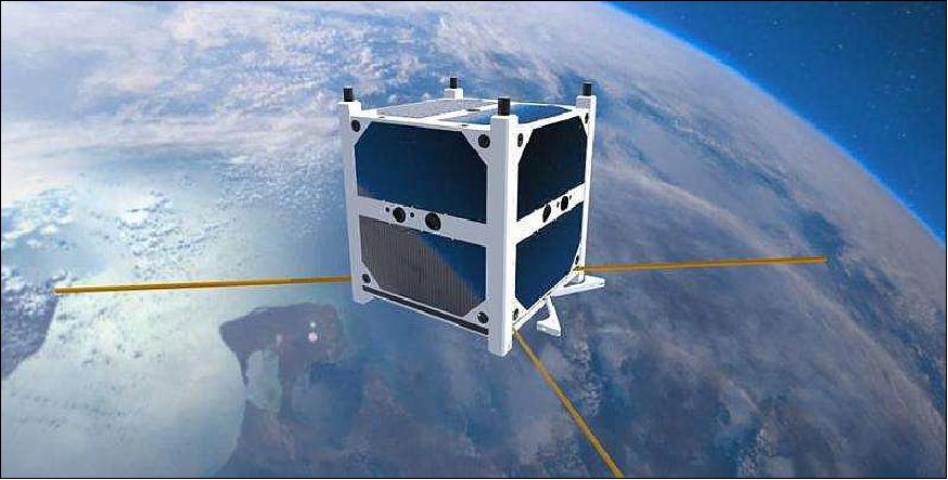
skCUBE is a 1U CubeSat, the first Slovak satellite, which was completely developed and constructed by the University of Zilina (UNIZA) in cooperation with the University of Technology (STU) in Bratislava and with SOSA (Slovak Organization for Space Activities), a non-governmental organization in Bratislava to promote space science in the Slovak Republic. The project is supported by the Slovak government. The overall objective is to gain hands-on experience with everything involved in satellite manufacturing and to strengthen Slovakia's position within the European Space Agency's (ESA's) group of cooperating states. CubeSats are an ideal way of gaining the know-how and experience in making relatively cheap experiments in space. 1)
Spacecraft
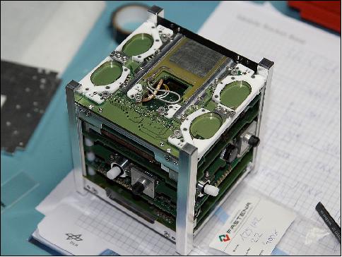
The skCUBE , with a mass of ~1kg and a size of 10 cm x 10 cm x 10 cm, was built essentially from scratch. Virtually all of CubeSat was designed and constructed by the project team, including the circuit boards, sensors, parts of the testing equipment, software and calibration methods The structure of the CubeSat uses aluminum which provides the required stiffness, endurance and heat conduction. Two solar panels are placed on each side of the cube. There are 5 pieces of PCB (Printed Circuit Board) connected with 104 pin connector inside the skelet. Dipole antennas and patch antenna will be deployed at the bottom of the satellite. 2)
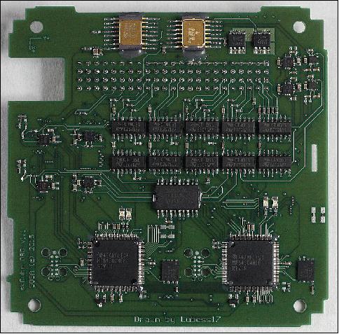
OBC (On-Board Computer)
The OBC is the brain of the satellite. It communicates with other peripherals, stores information to the internal memory and divides tasks. It is designed in a redundant way, so in the case of failure, control is taken over by a backup system. The heart of the OBC is the MSP430 processor with a static architecture and a connectable FRAM (Ferroelectric Random Access Memory) to improve its radiation resistance. Failure is equally detected by a radiation resistant watchdog, a component that monitors the work of the active microcomputer. The OBC also has a unique real-time operating system developed by the skCUBE team for a period of more than 3 years. 3)
COM (Communications subsystem)
COM is a redundant subsystem. Its primary channel works at a frequency of 437.1 MHz (UHF) and is used to transmit telemetry housekeeping data using the AX.25 protocol at a data rate of 9.6 kbit/s. The team also developed an S-band system with a frequency of 2.401 GHz for the transmission of imagery at a speed up to 240 kbit/s. With colleagues from Žilina University, the team developed progressive encoding methods using LDPC (Low Density Parity Check) channel codes, which will secure a reliable reception even at low SNR (Signal to Noise Ratio) levels.
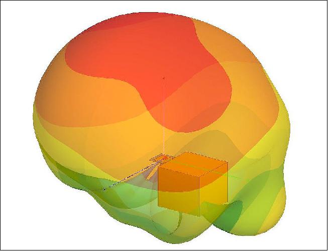
Communication inherently involves antennas. Here, the team had to figure out the antenna deployment and their release from their containers. The system works in such a way, that antennas are rolled inside the satellite like a measuring tape, blocked by doors and held by a thread. This system was developed to be very reliable, so that for instance the antennas would not deploy prematurely in the rocket, and the resistors would burn the holding thread and release the antennas at the right moment. The antennas are crucial for the communication system, which is why a great number of concepts and measurements were tried before the team found parametrically the right antenna design.
An interesting piece of the satellite's technology is the patch antenna for the 2.4 GHz S-band system, where the main problem was the available space for it. Thus, it had to fit within a space of 40 x 40 cm with a height of 1.5 mm. Nevertheless, the antenna has a good gain of 6 dBi and provides right-handed polarization.
ADCS (Attitude Determination and Control Subsystem)
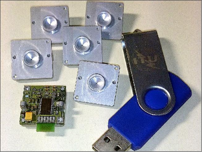
The ADCS is a complex system acquiring the position and orientation of the satellite, based on the information from on-board sensors the: magnetometer, gyroscope, sun sensor and Earth sensor. Both the magnetometer and gyroscope are small SMDs (Surface Mount Devices) with a MEMS structure, which are needed to be calibrated before use. The project used the system of Helmholtz coils and accurate fluxgate magnetometers for the calibration of the magnetometers. A unique component of the satellite is the sun sensor, which can be used to determine the position of the satellite with respect to the Sun. The Sun is a great navigational point in space within our Solar System. The sun sensor is made of a bilateral PSD (Position Sensitive Detector), which is subject to subsequent processing by an AD convertor. Its theoretical accuracy in its position determination can be up to 0.1º.
Furthermore, the last sensor for position determination is the Earth sensor. It is basically an infrared camera with resolution of 16 x 4 pixels, which is capable to determine Earth's horizon based on temperature contrast. By optimal fusion of these sensors, the team can determine position and orientation of the CubeSat on orbit. The CubeSat will gain initial random rotation after deployment from the launch vehicle, needed to compensate and stabilize the satellite. For rotation reduction, the team will use the B-dot algorithm, which can control active coils based on magnetic field measurements.
Active coils are electromagnetic coils with a core, which can interact with magnetic field of Earth. In fact, we'll use magnetic field line as a support point around which we turn the satellite. A big problem of such coils is the hysteresis of the core itself, which results in a remnant magnetism and which then interacts with further magnetic measurements. Therefore, the project manufactured a core with extremely small hysteresis loop. It took the team about a year to find the right material, do computer simulations, measurements, tests and build the core together with the wire winding.
EPS (Electrical Power Subsystem)
The EPS secures energy from the solar panels, stores it in batteries (LiFePO4 accumulators 2 x 1100 mAh) and distributes it into individual modules and subsystems. The design of the printed circuit board will last for about 2 years and it is the most complicated part of the whole satellite. The team had to fit approximately 1000 components into a very small space of 6 layers. Not all of the components could be purchased in high enough quality for deployment in space. Therefore, the rest of the components had to pass radiation tests, to be able to determine approximately their life expectancy. Based on these results,the original design had to be modified. Radiation measurements of the satellite's critical components have been secured by RCM together with the University Center of Electron Accelerators of the Slovak Medical University. The average power of EPS is 2 W.
Development status: The project delivered the skCUBE satellite to ISL ( Innovative Space Logidtics B.V.), the launch service provider of Delft, the Netherlands, in April 2016. ISL will secure the integration of skCUBE together with other CubeSats into a so called flight container. Subsequently, ISL will deliver skCUBE to the VAFB in California and mount it to SpaceX's Falcon 9 rocket.
Orbit
Sun-synchronous near-circular orbit, altitude of 505 km, inclination = 97.8º, LTDN (Local Time on Descending Node) at 9:30 hours.
Launch
The skCUBE satellite was launched as a secondary payload on 23 June 2017 (03:59 UTC) on the PSLV-C38 vehicle in XL configuration of ISRO from SDSC (Satish Dhawan Space Center), India. The primary payload on this flight was CartoSat-2E (~712 kg), the sixth satellite in the Cartosat-2 series (total launch mass of ~955 kg). 5) 6)
All 31 Satellites separated successfully. 7)
Secondary payloads (30 satellites with a total mass of 243 kg):
The Dutch company ISISpace (Innovative Solutions In Space) accommodated most of the secondary payloads aboard the multi-satellite launch. Engineers stowed the CubeSats in QuadPacks before shipping them to the Indian launch site.
Orbit: Sun-synchronous near-circular orbit, altitude of 505 km, inclination = 97.8º, LTDN (Local Time on Descending Node) at 9:30 hours.
Secondary payloads (30 satellites with a total mass of 243 kg):
The Dutch company ISISpace (Innovative Solutions In Space) accommodated most of the secondary payloads aboard the multi-satellite launch. Engineers stowed the CubeSats in QuadPacks before shipping them to the Indian launch site.
• NIUSAT (Noorul Islam University Satellite), located in Kumarakovil, Thuckalay, Kanyakumari District Tamil Nadu, India. NIUSAT is an Earth observation nanosatellite (15 kg). NIUSAT features a RGP camera with a ground resolution of 25 m and a frame size of 50 km x 50 km.
• CE-SAT-1 (Canon Electric Satellite-1), a microsatellite (50 kg) of Canon Electronics Space Technology Laboratory, Japan. The microsatellite features an optical imaging system based on a 40 cm diameter Cassegrain telescope.
• Max Valier, a nanosatellite (16 kg) of the "Max Valier" school Bolzano and the "Oskar von Miller" school Merano, in South Tyrol, Italy.
• D-SAT (Deorbit Satellite), a 3U CubeSat mission (3.5 kg) by the Italian company D-Orbit to demonstrate active end-of-life reentry.
• 3 Diamond nanosatellites (Blue, Green, Red) of Sky and Space Global, UK, developed by GomSpace ApS of Denmark. The three 3U CubeSats (each 6 kg) are pathfinders for Sky and Space Global's 200 Satellite LEO constellation.
• Pegasus, a nanosatellite (2U CubeSat) of FH Wiener Neustadt, Austria (thermosphere research). Pegasus is a member of the QB50 constellation with the m-NLP payload.
• InflateSail, a 3U CubeSat of SSC (Surrey Space Centre) at the University of Surrey, UK (technology demonstration nanosatellite). Part of the QB50 constellation.
• UCLSat (University College London Satellite), a 2U CubeSat of UCL with the INMS (Ion and Neutral Mass Spectrometer), ionosphere research. UCLSat is part of the QB50 constellation.
• NUDTSat (National University of Defense Technology Satellite), Belgium, a 2U CubeSat of NUDT for ionosphere research. NUDTSat features a FIPEX instrument of the QB50 constellation.
• COMPASS-2 (DragSail CubeSat), a 3U CubeSat of FH Aachen, Germany (technology demonstration nanosatellite). COMPASS-2 is part of the QB50 constellation.
• LituanicaSAT-2, a 3U CubeSat of Vilnius University, Lithuania. The CubeSat is part of the QB50 constellation with a FIPEX payload.
• URSA MAIOR (University of Rome la SApienza MicroAttitude In ORbit testing), a 3U CubeSat to study the lower thermosphere. USRA MAIOR is a member of the QB50 constellation with the m-NLP payload.
• VZLUSat-1, a 2U CubeSat Czech technology nanosatellite of VTLU, developed in cooperation with Czech companies (RITE, HVP Plasma, 5M, TTS, IST) and universities (CVUT, University of West Bohemia). The nanosatellite carries on board the following experiments: a miniaturized X-ray telescope, composite material for radiation shielding, FIPEX, a QB50 instrument, to measure the concentration of oxygen in the thermosphere.
• SUCHAI-1 (Satellite of the University of Chile for Aerospace Investigation), a 1U CubeSat (1 kg).
• Venta-1, a nanosatellite (7.5 kg) of Ventspils University, Latvia, developed by Ventspils University College in cooperation with Ventspils High Technology Park, Bremen University of Applied Sciences and OHB Systems.
• Aalto-1, a Finnish student nanosatellite (3U CubeSat) of Aalto University, Aalto, Finland.
• ROBUSTA-1B (Radiation on Bipolar Test for University Satellite Application), a nanosatellite with a scientific experiment developed by the University of Montpellier students (France), a successor to the ROBUSTA satellite, which was launched in February 2012.
• skCube, a 1U CubeSat for educational and popularization outreach developed by SOSA (Slovak Organization for Space Activities ) at the University of Zilina. It is Slovakia's first satellite.
• CICERO-6 (Community Initiative for Cellular Earth Remote Observation-6), a 6U CubeSat of GeoOptics Inc. (~10 kg), Pasadena, CA, built by Tyvak Nanosatellite Systems. The objective is to demonstrate radio occultation observations for a commercial customer. CICERO-6 features Cion (CICERO Instrument for GPS-RO) with a mass of 1.2 kg. Cion has a size of 30 x 10 x 6 cm, power of 8 W. 8)
• Tyvak-53b, a technology demonstrator by Tyvak Nanosatellite Systems, Inc. (Irvine, CA) for deorbiting of nanosatellites.
• Lemur-2 x 8. Lemur-2 is commercial satellite constellation of Spire Global Inc., San Francisco, CA, The objective of the Lemur-2 constellation is ship tracking via AIS (Automatic Identification System) with SENSE. The STRATOS instrument makes use of GPS occultation measurements to determine temperature, pressure and humidity profiles of Earth's atmosphere for application in operational meteorology.
Sensor Complement
VLF Experiment
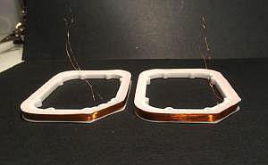
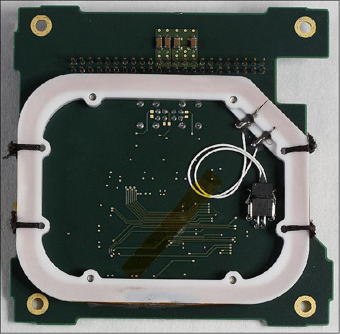
The scientific experiment is a VLF (Very Low Frequency) receiver of radio signals in the 3-30 kHz band range, capable of subsequent signal processing. The goal is to use the system for the detection of so-called whistlers to study terrestrial lightning and Earth's ionosphere. The detector consists of a nearly square-shaped air-core loop/coil (Figure 2), which serves as an antenna of the VLF receiver, a coil with a 1000 windings and a cross-sectional area of 42 cm2. The coil signal is amplified, converted in an AD converter and processed in a microcontroller. Digital filtration of the signal, spectral analysis and event detection based on power flux density is performed on-board as well.
The experiment works in 2 modes. The first slow one allows for the monitoring of the evolution of spectral changes throughout skCUBE's orbit and the detection of potential anomalies. The second mode executes very fast sampling of the detected signal, based on an excess of power flux density over specific limits, which will be set in the orbit. It will allow for the analysis of fast events occurring in the top side of the ionosphere. 9)
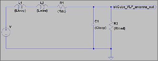
Properties of the magnetic loop antenna: The VLF antenna can be approximated by the diagram shown in Figure 4. It consists of an ideal voltage generator V with a value defined by the equation:

where V is the induced voltage in Volts, µ0 is the permeability of vacuum equal to 4π x10-7H/m, N is the number of coil turns, A is the area of each winding in m2, ν is frequency in Hz, Hrms is the RMS value of the magnetic field's strength in A/m, θ is an angle between the magnetic field vector and the coil frame normal. The circuit includes further loop inductance Lloop (the inductance of the wire winding around the frame), wire inductance Lwire (the inductance of the wire of the antenna winding), wire resistance Rdc and the distributed capacitance Cloop. Each of the elements contributes to the antenna's performance and properties.
Measured properties:
• L = 150 mH (inductance)
• Rdc = 390 Ω (resistance)
• f0 ~70 kHz (resonance frequency)
The VLF detector works with antenna's current over wide frequency band and Rload → 0.
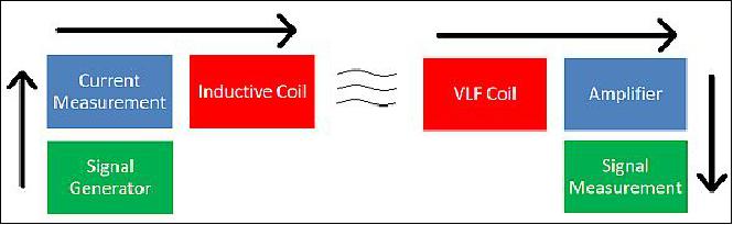
Legend to Figure 9: Arrows indicate measurement sequence from signal generation, with pre-determined properties, up to its amplification and final detection. The signal generator (PC sound card); current measurement (Fluke 287 multimeter); inductive coil (one loop with a diameter of 25 cm, distance 17 cm from the detection VLF coil); amplifier (OPA2314); signal measurement (Creative X-FI USB sound card).
Signal processing: The signal processing has a hardware part and a software part (Figure 10). The hardware part consists of an antenna, the air-core VLF coil, which is connected to a transimpedance amplifier (TIA) and which transforms the current from the coil to voltage. The output voltage is therefore directly proportional to the magnetic flux. That signal goes further into an anti-aliasing filter with a threshold frequency of 25 kHz.
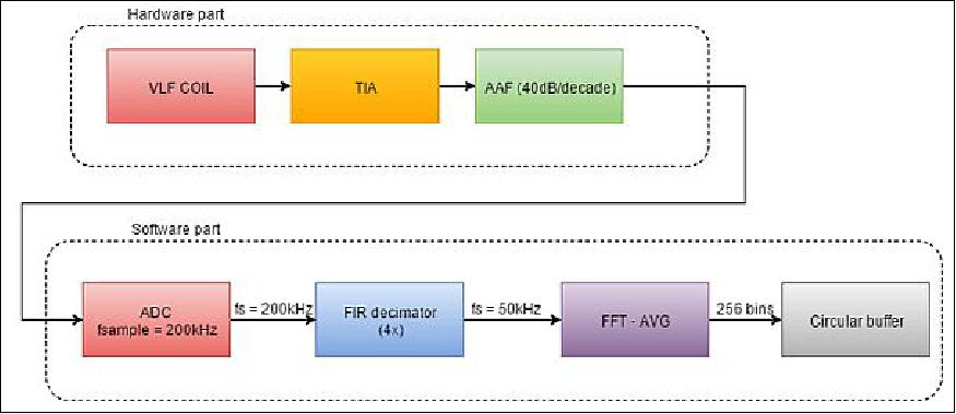
Legend to Figure 10: TIA (Transimpedance Amplifier), AAF (Anti-Aliasing filter), ADC (Analog-to-Digital Converter), FIR (Finite Impulse Response), FFT (Fast-Fourier transform).
The software part begins with an internal analog-to-digital converter of a microprocessor, which samples the signal at a frequency of 200 kHz. When samples reach buffer limits, the FIR decimates the under-samples input signal by a factor of 4. These output samples then undergo spectral Fourier analysis using 256 frequency bins. The signal is further averaged in the spectral domain. The spectral signal is stored in a circular buffer.
Summary of the basic signal processing parameters:
- ADC resolution: 12 bits
- number of input channels: 3 (the multiple channels are connected to active coils utilized primarily for the stabilization of the satellite, but they are able to detect VLF radio waves as well. We plan to describe them more in detail in our future publications)
- sampling frequency of ADC: 200 kHz
- simultaneous sampling: no
- decimation: 4x - 80 TAPS FIR
- buffer size: 50000 samples
- buffer processing period: 125 ms
- buffer processing time: 40 ms
- FFT: 256 bins.
VLF radio waves in low-Earth orbit and related scientific research
Sources of VLF radio waves in the Earth's low orbit will be primarily lightning discharges, the ionosphere, charged particles in the magnetosphere and human-related activity. The spectrum of such radiation depends on the properties of the source and the location of its origin. If the location of the source is close to the ground, the signal must pass through the ionosphere. Plasma in the ionosphere changes the waves' original properties. The characteristics of such waves can thus reflect the charged particle densities in the ionosphere and the properties of the omnipresent magnetic field.
Whistlers: Whistlers are typical radio signals in the VLF band from dispersed frequency components of the lightning spectrum. Travel through the ionosphere causes high frequencies to arrive first (Figure 11). Their sources near skCUBE's low orbit will be thunderstorms over which the satellite will fly . This means that whistlers will come into the VLF detector from below. The characteristics of whistlers depend on the properties of the lightning itself, together with the free electrons, ion density and the magnetic field in the ionosphere.
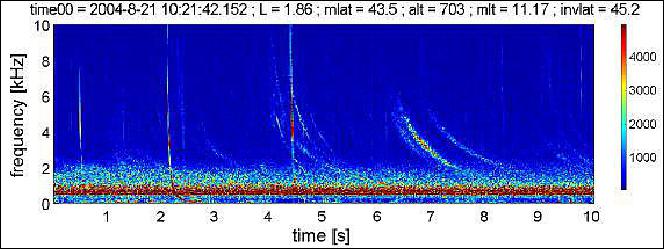
The properties of the whistlers can be approximately explained by Appleton's equation, which expresses the phase refractive index for electromagnetic waves passing through magnetized plasma. In this case, it will be the Earth's ionosphere, due to ultraviolet radiation and X-rays coming from the Sun, which ionize upper parts of our atmosphere. Appleton's equation considers only the effects of free electrons and for more precise understanding of whistlers, free ions will need to be taken into consideration. Therefore, the analysis of whistlers will also bring new information about the ionosphere, which is ultimately important for any radio communication and position measurements between the Earth and satellites in space.
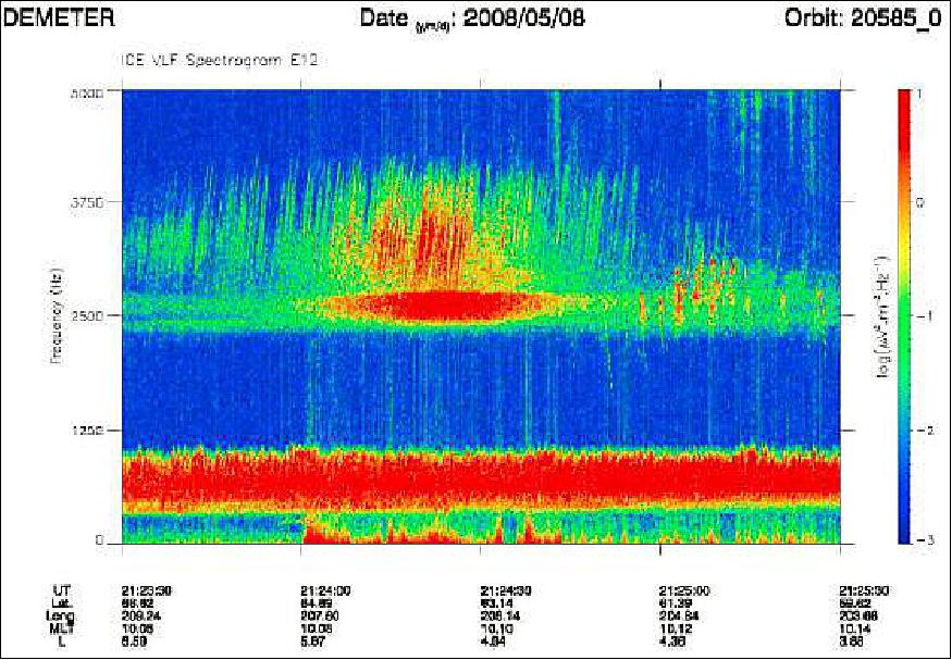
Chorus: Another type of radio signal visible in the VLF band, with a potential to be detected by the skCUBE receiver, is a chorus (Figure12), generated by the interaction of radio waves with energetic electrons at around 3-10 Earth radii from its core. A chorus can reach skCUBE from above along magnetic field lines at higher geomagnetic latitudes.
In summary, the experimental air-core loop receiver is set up for wide band detection of very low frequency radio waves with a minimum intensity of a magnetic field around 4.2 x10 -5 A/m (B ~ 5.3 x 10⁻¹¹ T). At this level, the project team should primarily hear radio signals from lightning, called whistlers. One of the problems of the current detector is its proximity to the internal electronics, whose noise influences the sensitivity of the detector. A potential technological solution of this issue could be to place the detector on the boom outside of the CubeSat's skeleton.
CAM (Camera)
The objective of CAM is to take images of the Earth. In particular, the goal is to take imagery of Slovakia. The camera features an image detector of 750 x 480 pixels. The optics have a field view of 60 degrees and contain an infrared (IR) and neutral density (ND) filter. Image processing is performed by a microcontroller STM32F407, which also does all of the post-processing, including JPEG compression. A picture snapshot from orbit can be scheduled from the ground and stored into an external FLASH memory.
Ground segment
The ground segment will receive, decode and store received data from the skCUBE mission The primary ground station is being built at Šamorin, a small town southeast of Bratislava. It will be run by the ham radio organization SOSA – OM3KAA, with the main operator OM1LD.
This ground segment is a unique project by itself. The concept of the Slovak manufacturer allows for precise tracking of satellites with an accuracy better than 0.1 degree using a 100 kg parabolic antenna, which is necessary for keeping connections on frequencies higher than 1 GHz. This ground segment will be possible to use also for the follow-up missions and other scientific and ham radio projects.
The secondary ground segment will be built at the University of Zilina. For signal reception of the satellite, the project will also use the services of other receiving stations, for example one of the RMC company in Nová Dubnica. An important part of the ground segment is the decoding software, which allows for clear display of the telemetry data from individual systems and which was developed by the project as well.
References
1) Jakub Kapuš, Ondrej Závodský, Robert Lászlo, Jaroslav Erdziak, Rudolf Slošiar, Miroslav Šmelko, Pavol Lipovský, Ľubomír Pasternák, Martin Magyar, Michaela Musilová, "First Slovak Satellite skCUBE," Proceedings of the 4S (Small Satellites, System & Services) Symposium, Valletta, Malta, May 30-June 3, 2016, URL: http://congrexprojects.com/docs/default-source
16a02_docs/4s2016_final_proceedings.zip?sfvrsn=2
2) "skCUBE Slovak first satellite," ITU Symposium and Workshop on small satellite regulation and communication systems, Prague, Czech Republic, 2-4 March 2015, URL: https://www.itu.int/en/ITU-R/space/workshops/2015-prague-small-sat/Presentations/SVK-poster.pdf
3) J. Slačka, et al., "Safety critical RTOS for space satellites," 20th International Conference on Process Control (PC), IEEE,Strbske Pleso, Slovakia, June 9-12, 2015, pp. 250–254, DOI: 10.1109/PC.2015.7169971
4) Tomasz Nowakowski, "Slovakia to send its first ever satellite into space," April 11, 2016, URL: http://phys.org/news/2016-04-slovakia-satellite-space.html
5) "PSLV-C38 / Cartosat-2 Series Satellite," ISRO, June 23, 2017, URL: http://www.isro.gov.in/launcher/pslv-c38-cartosat-2-series-satellite
6) "Indian Launch Manifest of April 15, 2017," URL: http://www.sworld.com.au/steven/space/india-man.txt
7) "PSLV-C38 / Cartosat-2 Series Satellite Mission: All 31 Satellites separated successfully," ISRO, June 23, 2017, URL: http://www.isro.gov.in/update/23-jun-2017/pslv-c38-cartosat
2-series-satellite-mission-all-31-satellites-separated
8) Dave Williamson, "Small Satellites: The Execution and Launch of a GPS Radio Occultation Instrument in a 6U Nanosatellite," 33rd Space Symposium, Colorado Springs, CO, USA, April 3-6, 2017, URL of presentation: https://www.spacesymposium.org/wp-content/uploads/2017/10/Williamson_Dave_GPS_Radio_Occultation_Talk-v1.pdf
9) Michaela Musilová, Ondrej Závodský, Jakub Kapuš, Rudolf Slošiar, Miroslav Mocák, Robert Lászlo, Ľubomír Pasternák, Miroslav Šmelko, Pavol Lipovský, "Very-low-frequency radio waves detector of the first Slovak satellite skCUBE," Proceedings of the 67th IAC (International Astronautical Congress), Guadalajara, Mexico, Sept. 26-30, 2016, paper: IAC-16.B1.3.9
10) Michel Parrot, Ondřej Santolík, František Nĕmec, "Chorus and chorus-like emissions seen by the ionospheric satellite Demeter," Journal of Geophysical Research: Space Physics, Vol. 121, Issue 4, April 2016, pp: 2813–2817, DOI: 10.1002/jgra.52096
The information compiled and edited in this article was provided by Herbert J. Kramer from his documentation of: "Observation of the Earth and Its Environment: Survey of Missions and Sensors" (Springer Verlag) as well as many other sources after the publication of the 4th edition in 2002. - Comments and corrections to this article are always welcome for further updates (eoportal@symbios.space).
Spacecraft Launch Sensor Complement Ground Segment References Back to Top