Shi Jian-9 (SJ-9)
Non-EO
CAST
Quick facts
Overview
| Mission type | Non-EO |
| Agency | CAST |
| Launch date | 14 Oct 2012 |
SJ-9 (Shi Jian-9 Formation Flight Mission)
Overview Spacecraft SJ-9A Spacecraft SJ-9B Launch Mission Status Technology Demonstrations References
SJ-9 (Shi Jian means "Practice" in Chinese) is a technology demonstration formation flight mission of CNSA (China National Space Administration), consisting of two minisatellites of different sizes and capabilities, SJ-9A and SJ-9B. The overall mission concept is to demonstrate the functionality of a range of newly developed formation flying techniques and components and to validate the formation flight GNC (Guidance, Navigation and Control) algorithms and strategies of the system configuration. 1) 2)
Space Segment
The SJ-9A small-satellite uses the mature CAST-2000 platform which can support the test of key techniques including electronic propulsion system, high-performance small camera, etc. The SJ-9B micro-satellite is based on the new CAST-100 platform which validates key instruments and components, such as LWIR focal-plane component, low temperature cold optics, long life time Stirling cryocooler ,etc. The two spacecraft were designed and developed by DFHSat (DFH Satellite Company Ltd.) of CAST (China Academy of Space Technology), Beijing.
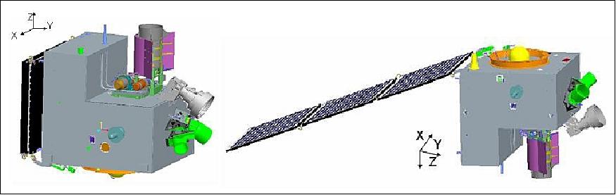
SJ-9A Spacecraft
Use of the CAST-2000 platform providing high attitude control precision and stability. It has an S-band TT&C subsystem and an X-band data transmission subsystem, data integration is provided with the OBDH (OnBoard Data Handling) subsystem using the CAN bus for communications; a high power generation capability is provided.
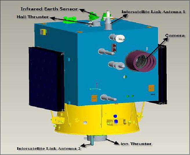
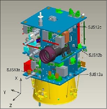
The satellite is composed of the electronic module, propulsion module and payload module. Hall electric propulsion and ion electric propulsion are installed separately on the +X surface and -X surface. The camera is installed on the bottom plane of the payload module.
Two ISL antennas are installed on +X surface and -X surface. The satellite features a flash memory recorder.
The monitoring unit of the Electric Propulsion Test Subsystem - composed of a quartz crystal microbalance, Langmuir probe and retarding potential analyzer - is required to provide the following functions:
• Measurement of the plasma parameters around the satellite (exhaust plume) during the operation of electric propulsion
• Directly measure pollution caused by electric propulsion
• Monitor satellite floating potentials influenced by electric propulsion.
Spacecraft launch mass, bus size | 790±30kg, 1300 mm x 1310 mm x 1988 mm |
Spacecraft shape dimension | ∅ 2900 mm x 2487 mm |
Spacecraft power | 357 W (long-term), 1350 W (short-term) |
Orbit | SSO, altitude of 623 km x 650 km, inclination = 98º, LTDN= 10:30 hours |
ADCS (Attitude Determination and Control Subsystem) | - Three-axis stabilized, Earth-pointing attitude |
EPS (Electrical Power Subsystem) | - Solar array size: 5.661 m2(1110 mm x 850 mm x 6) |
Data transmission subsystem | - X-band, downlink data rate: 190 Mbit/s (payload data) |
ISL baseline measurement | - Transfer rate: 4096 bit/s |
Electric Propulsion Test Subsystem | - Thrust: 40 mN±4mN |
Payload | Pan camera: 0.45~0.89 µm |
Some remarks on the electric propulsion systems (Ref. 1):
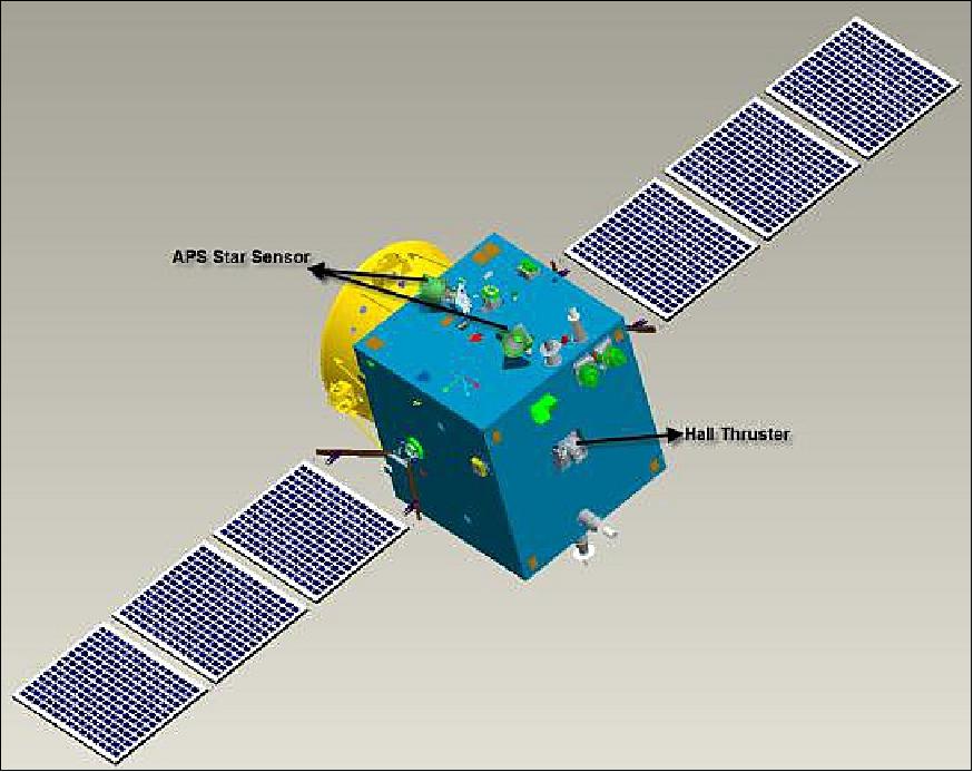
Two electric propulsion demonstration systems are integrated into the SJ-9A spacecraft:
• Ion Electric Propulsion
• Hall Effect Propulsion.
The electric propulsion technology is relatively complex, requiring a fairly large power generation capability of the spacecraft. This has consequences for the design of the radiator as well as for the insulation technology. It also correlates with the satellite configuration layout, power source, attitude and orbit control, thermal control and the design of other subsystems.
The electric propulsion system has two kinds of adverse influences on the satellite platform. The exhaust plume of electric propulsion may interfere with the in-situ environment, it may also cause electromagnetic interference. These effects must be accounted for in the electro-magnetic compatibility design to ensure safety and cleanliness, in particular for the payload instrument measurements during those periods, when the electric propulsion system is operated.
The technical challenges of ion electric propulsion include the design and processing of ion optics component, long-life solution of the hollow cathode, control of the micro-flow rate, high voltage protection design, and the ion power processing unit. The technical challenges of the Hall effect propulsion include: micro-flow rate control, hollow cathode exposed problem in atmosphere, Hall power source processing unit. The solution of the key technology is verified by all kinds of experiments.
The objective of the SJ-9A spacecraft is to demonstrate and validate these electric propulsion technologies on orbit. The requirements call for the demonstration of the following items/parameters:
• Measurement of the plasma parameters around the satellite when the electric propulsion is active.
• Measure the pollution in the vicinity of the payload instruments caused by the exhaust plume.
• Monitor the satellite floating potentials influenced by electric propulsion.
The plasma environment change and pollution depositional environment caused by the electric propulsion is monitored by the diagnostic units of electric propulsion subsystem, which is composed of the quartz crystal microbalance, the Langmuir probe, and the retarding potential analyzer.
Sensor Complement
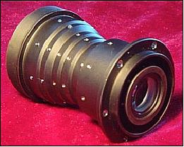
High-Performance Small Camera
The camera features an integrated panchromatic and multispectral design which uses three reflecting mirrors coaxial aspheric optical technology, a multicolor device, an electronic focal component, a management controller, and an imaging control and thermal control technology. The fore telescope of the camera uses the new cyanide ester resin materials.
When the camera is observing on orbit, five CCD line spectra are generated in pushbroom mode, forming five overlapping stripmap images. The panchromatic and multispectral images of the camera are processed by the ground application system.
The camera is comprised of a telescope and focal plane component. The three-reflector coaxial aspheric optical system with a focus of 2.6 m, a relative aperture of 1/10, and a field angle along the x-direction of 2.7° is selected in order to meet the requirements of ground imaging swath width and high ground sample distance.
The spectral/spatial parameters of the camera are listed in Table 1.
The high-performance small camera pixel resolution is < 2.5m (panchromatic)/10m (multispectral) at an orbital altitude of 645 km, on a swath of 30 km. The mass of the camera main body is < 42 kg. The dynamic MTF on orbit is better than 0.12.
SJ-9B spacecraft
SJ-9B uses the new CAST-100 platform of DFH, the second satellite using the autonomic research and development platform. In flight, the satellite points to the sun during test time, or to target during imaging observation.
Spacecraft launch mass, bus size | 260±20kg, 1081 mm x 1072 mm x 1030 mm |
Spacecraft shape dimension | ∅ 1900 mm x 1452 mm |
Spacecraft power | 270 W (long-term), 350 W (short-term) |
Orbit | SSO, altitude of 623 km x 650 km, inclination = 98º, LTDN= 10:30 hours |
ADCS (Attitude Determination and Control Subsystem) | - Three-axis stabilized, Earth-pointing attitude |
EPS (Electrical Power Subsystem) | - Solar array size: 2.8 m2(1110 mm x 850 mm x 3) |
Data transmission subsystem | - S-band (USB) TT&C, downlink at 4 kbit/s, uplink at 2 kbit/s |
ISL baseline measurement | - Transfer rate of GPS data: 4096 bit/s. |
Payload: | LWIR camera: 8±0.5 µm~12+1 µm |
Sensor Complement
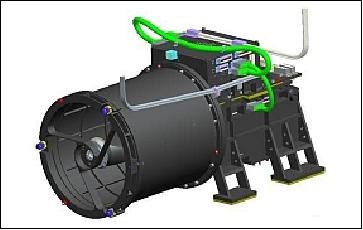
LWIR (Long Wave Infrared) Camera
The goal of the LWIR camera is to test mainly the functions of the instrument such as the focal-plane component(256 x 1) and the long-life Stirling cryocooler which is designed to function as an autonomic research and development component. The camera features low-temperature optics. The operational temperature of optical system is kept in the range of -35ºC to -20ºC. The Stirling cryocooler has a cooling capacity of 65K @ 1 W. The spectral/spatial parameters of the camera are listed in Table 2.
The LWIR camera on SJ-9B uses a low-temperature optics design, long-life large refrigerating output design, long-wave infrared detector design, etc. It extended the infrared image band from 10.5-12.5 µm. The cold optics design technology can restrain background radiation and raise the detection performance.
Launch
The two spacecraft, SJ-9A and SJ-9B, were launched successfully on October 14, 2012 (UTC) on a CZ-2C vehicle with an SMA solid motor upper stage. The launch site was the TSLC (Taiyuan Satellite Launch Center), China. 3) 4)
Orbit: Sun-synchronous orbit, altitude of 623 km x 650 km, inclination = 98º, LTDN = 10:30 hours.
Mission Status
• According to the CEOS database, the SJ-9A and SJ-9B spacecraft are operating in 2016. 5)
• The SJ-9A and SJ-9B spacecraft are operating nominally in 2013 (Ref. 2).
The SJ-9 spacecraft have completed the technology demonstration tests for a total of 25 payloads. Flight results showed that all test payloads functioned nominally and their performance met the technical requirements.
• On 7 November 2012, at 9:10 Beijing Time, the LIPS-200 ion electric thruster on the SJ-9A satellite made a successful firing lasting 3 minutes. It was the first time for China to test an electric propulsion system in space. One hour and 40 minutes later, another electric thruster on the same satellite, the LHT-100 Hall Effect electric thruster, was fired for 180 seconds. At 12:28, the LIPS-200 made the second firing for 4 minutes. Up to 14 November, it has completed the first phase of in-orbit testing with 12 firings. According to the plan, the LIPS-200 will be tested for 200 firings totalling 50 hours. 6)
• On Oct 19, 2012, SJ-9A began maneuvers, lowering its orbit to 619 x 644 km and then returning to a 623 x 650 km orbit on Oct 22-23.

Technology Demonstrations
Formation Flight and High Precision Baseline Measurement of Two Satellites
Relative motion of formation flight is generally described in the orbit coordinate system of the target satellite. The on-orbit coordinate system (O-xyz) is defined; the origin O is the centroid of the target satellite, where the z-axis points toward nadir (geocentric point) in the orbit plane, and the x-axis points into the flight direction of the spacecraft.
The implementation employs CDGPS (Carrier-phase Differential GPS) for high-precision ISL (Intersatellite Link) baseline measurements. The requirements call for a measurement precision of < 10 cm, and for a time synchronization precision of < 9 ns.
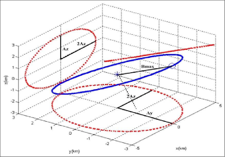
The SJ-9A satellite is the active spacecraft of the formation which is expected to maneuver around the SJ-9B satellite. The effective length of the baseline between the two satellites is 3 km±1.5 km and the angle between the flying-around surface and the local level is 35±5°in the formation flight.
The formation-flying configuration of the two satellites is carried out in the same semi-major axis and orbit inclination. The relative motion of direction in the x and z direction is formed by using the relative eccentricity; the relative motion in the y-direction between the formation-flying satellites is formed by using the ascending node difference. In this way, the two satellite configuration is shaped by an ellipse. Figure 8 illustrates the formation-flying space ellipse, the motion scale of the three directions, Ax, Ay and Az are designed based on the requirement of an interactive baseline. In the illustration of Figure 8, Ax is about 4 km, Ay is about 3 km, and Az is about 2 km (Ref. 1).
Initialization of the formation configuration: The two spacecraft are being launched by one rocket. After deployment, SJ-9A and SJ-9B can pull apart in the initial phase by the relative separation speed between the satellite and the rocket. After testing of the on-orbit drifting configurations, the satellite orbit parameters will be adjusted by ground control to obtain the formation configuration. The configuration is formed mainly by eccentricity difference, phase difference, ascending node difference, and the argument of perigee difference of the two satellites. 7)
1) Adjustment of the phase difference: After deployment, there is a natural phase difference between the satellites in the on-orbit test phase. By adjusting the orbit semi-major axis and changing the phase relative drift ratio, the phase difference will be formed in accordance with the configuration design.
2) Adjustment of the eccentricity and argument of perigee: The adjustment of the eccentricity vector (including the eccentricity and the argument of perigee) and semi-axis is relative. By adjusting the speed increment (position and time) and the semi-major axis, the argument of perigee and eccentricity of two satellites can be achieved.
3) Ascending node difference formation: The ascending node difference is directly controlled; the best control position is at the orbit phase of ±90º. Based on the configuration design, the ascending node difference of the two satellites is ΔΩ ~ 0.025º, and speed increment required is about 3.3 m/s. The baseline between the two satellites can be achieved by the relative ascending node drift due to the semi-axis difference in the formation of the phase difference. The control of the ascending node difference is based on measurement by ground control. The forming of the ascending node difference is based on the SJ-9B satellite orbit (target) by adjusting the SJ-9A orbit.
The reader is referred to the paper of reference 1) for technical details on the topics of:
• Formation configuration maintenance
• Formation flight mode
• High-precision ISL baseline measurement.
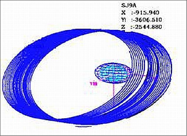
Automatic Formation Flight and High Precision Baseline Measurement of Two Satellites: The SJ-9A and SJ-9B satellites employ the cross-track technique to form formation flight. The formation flying mode focuses on relative orbit motion control, which includes some sub-modes, such as, precise following excursion and keeping control, out-of-planar relative motion transferring, transferring from following to flying-around, flying-around and keeping control, withdrawing from fly-around, etc. (Ref. 2).
The designed formation configuration is shown in Figure 8, Figure 9 shows the flight test result. During formation flying in orbit, the length of the effective baseline between two satellites is 3 km±0.7 km and the angle between around ellipse plane and local horizontal plane is 35°±0.6°. The advanced technologies include formation build from out-of-plane to in-plane autonomous control on-board technology, autonomous formation keeping for long term on-board technology. The measurement accuracy of inter-spacecraft baseline is less than 3 cm by using the carrier phase DGPS method between SJ-9A and SJ-9B spacecraft.
Efficiency Validation of Two Electric Propulsion Systems
The IEPS (Ion Electric Propulsion System) and HEPS (Hall Electric Propulsion System) were successfully tested on SJ-9 satellite. According to the thrust calibration in orbit, the thrust of the Xe ion thruster is 36.2 mN, the specific impulse is 2710 s. The thrust of Hall thruster is 38.3 mN, the specific impulse is 1500 s. The crystal microbalance, the Langmuir probe and the retarding potential analyzer onboard took charge of the measurement of the plasma environment changing and contamination aggregations. These parameters corresponded with those of international products. The first successful introduction of electric propulsion technology on SJ-9 spacecraft provided a solid basis for the future application of electric propulsion in Chinese missions.
Propulsion system | Parameter | Specification | Test result |
Hall thruster | Thrust | 40 mN ± 4 mN | 38.3 mW |
Xe-ion thruster | Thrust | 40 mN ± 4 mN | 36.2 mN |
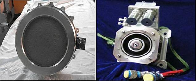
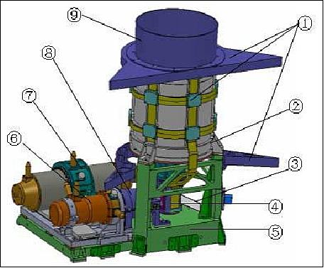
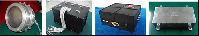
LIPS-200 (Lanzhou Institute of Physics System-200) of Lanzhou, Gansun, China. 8) 9)
LIPS-200 is an IEPS (Ion Electric Propulsion System) with the objective to demonstrate and space-qualify the system on the SJ-9A mission for China's GEO satellite NSSK (North-South Stationkeeping) applications. The following flight test goals are to be demonstrated on the SJ-9A mission:
• To validate the IEPS's adaptability to the space environment
• To scale the IEPS's performance in orbit
• To validate the stability and repeatability of the IEPS firings in orbit
• To validate the compatibility between the IEPS and the satellite's other systems.
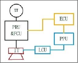
The IEPS on SJ-9A satellite is a single-string system based on the LIPS-200 IT (Ion Thruster). IEPS is comprised of the following subsystems:
- IT (Ion Thruster)
- PPU (Power Processing Unit)
- ECU (Electric-propulsion Control Unit)
- XT (Xenon Tank)
- PRU&FCU (Pressure Regulation Unit and Flow Control Unit)
- LCU (Line Connection Unit). The LCUs functions are not only the cable connecting box between PPU and IT, but also the electric-check interface.
Test phases of IEPS:
1) The first test phase of IEPS was carried out on Dec. 10, 2012. A total of 22 firings were performed, including three 3-minute firings, eighteen 10-minute firings, and one firing for break-down protection. All 21 tests were completed faultlessly, except for the break-down protection test. The IEPS worked well and stable.
2) The second test phase started from March 14, 2013. A simplified pretreatment procedure was initiated due to long interval of the last firing sequence. One hour of cathode and neutralizer pretreatment and a half hour of discharge chamber pretreatment had been conducted, respectively. The first formal 10-minute firing was conducted on March 15, 2013, and the telemetry data were normal.
- The goal of the second test phase was to accumulate up to 200 firing instances, and the accumulated time should be longer than 30 hours. By the end of July, 2013, the IEPS had fired more than 130 times with an accumulated time > 20 hours. The second test phase is are still underway and should be completed in 2013.
The telemetry data showed that the IEPS and each element worked well so far, and the IEPS is compatible with the other systems on the satellite. The performance on orbit parameters are:
- Input power of 1165 - 1225 W
- Thrust of 36.1 - 40.8 mN
- Specific impulse of 2726 -3081 s.
All parameters meet the requirements.
Parameter | Requirement | Achievement |
Thrust | 40±4 mN | 39.9 mN |
Specific impulse | 3000±300 s | 3136 s |
Maximum input power(42 V bus) | ≤1350W | 1209 W |
IEPS dry mass | ≤37 kg | 36.3 kg |
Startup time | ≤600 s | 242 s |
Time for single firing | 300~900 s | 900 s |
Total number of firings | ≥200 | 400 |
Protection response for neutralizer extinguish | ≤3 ms | 2.0 ms |
Beam divergence(90%) | <30º | 28.0º |
Thrust vector stability | ≤0.5º | 0.35º |
Leakage | <1 x 10⁻⁵ Pa m3/s | 5.6 x 10⁻⁵ Pa m3/s |
Reliability at end of life | 0.98 | 0.985 |
Design life | 3 years | 4 years |
Xenon mass | 1.5±0.5 kg | 1.60 kg |
Xenon purification level | 99.995% | 99.995% |
First Application of Super Capacitor
A 20,000 F super capacitor unit was successfully demonstrated on orbit. This technology is providing a solution to the requirements of instant high power supply in space application.
First Application of a High-Temperature Super-Conduction Filter
The high-temperature super-conduction material is working in a super-conduction state whenever the cooler control is thermally stable and the temperature is maintained at 75.5 K±0.2 K . The temperature stability parameters of cooler meet the requirement of ±1 K. The super-conduction filter decreases noises of the micro-wave receiver and increases the system sensitivity and anti-jamming ability.
Important Improvement Test of a New Attitude and Control Device
The measurement accuracy of the APS (Active Pixel Sensor) star sensor is better than 3 arcseconds. The ability of removing stray light is up to 27.5º.
The magnetic bearing-supported flywheel adopted a new- type rotor mixed magnetic bearing and realized a five degree of freedom active control. The active vibration control of the mixed magnetic bearing rotor restrains synchronized vibration on a large scale and achieves micro-vibration of the flywheel (Figure 13).
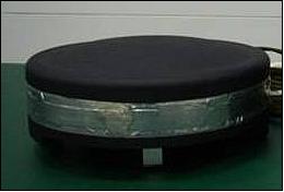
The in-orbit test of the APS sun sensors, HRG (Hemispherical Resonator Gyro), micro-flywheel and of the Micro Star Sensor (Figure 13) had also achieved the expect results.
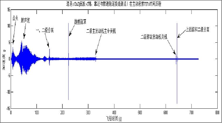
On-Orbit Vibrating Response Measured and Data Stored
The structural vibration measurement unit on SJ-9A recorded the whole data from vehicle launch to solar array deployment, and obtained the satellite vibration characteristics during the above mentioned periods. These data will benefit the anti-vibration design, and optimize the dynamic environment tests on ground in the future.
References
1) Zhi-ming Zhao,Ming Li, Yi-wei Liu, Bin Xie,Feng Zhai, Fang Yao, "The Key Demonstrations of High-Precision Formation Flight for Two Satellites," Proceedings of the 63rd IAC (International Astronautical Congress), Naples, Italy, Oct. 1-5, 2012, paper: IAC-12-B4.2.5
2) Zhiming Zhao, Yiwei Liu, Bin Xie, Feng Zhai, Fang Yao,"Flight result and achievement of SJ-9 Technology Demonstration Satellite," Proceedings of the 64th International Astronautical Congress (IAC 2013), Beijing, China, Sept. 23-27, 2013, paper: IAC-13-B4.6A
3) Rui C. Barbosa, "Long March 2C launches Shijian-9 tech demonstrator satellite duo," NASA, Oct. 13, 2012, URL: http://www.nasaspaceflight.com/2012/10
/long-march-2c-shijian-9-tech-demonstrator-satellite-duo/
4) "Long March 2C launches Shijian(Practice)-9(A/B) tech demonstrator satellite," Chinese Defence, Oct. 14, 2012, URL: http://www.defence.pk/forums/chinese-defence/213129-long-march-2c-launches-shijian-practice-9-b-tech-demonstrator-satellite.html
5) http://database.eohandbook.com/database/missionsummary.aspx?missionID=742
6) "Go Taikonauts," Issue 7, January 2013, URL: https://isulibrary.isunet.edu/opac/doc_num.php?explnum_id=590
7) Ming Li, Zhiming Zhao, Yiwei Liu, "SJ-9 Formation Flying Mission, the result," Proceedings of the 7th International Workshop on Satellite Constellation and Formation Flying (IWSCFF-2013), Lisbon, Portugal, March 13-15, 2013, paper: IWSCFF-2013-08-06
8) Tianping Zhang, Xiaoyong Wang, Haocheng Jiang, Shaoning Wang, Jun Gao, Jinling Xu, Tieming Cui, Fuquan Yang, Ning Guo, Fujun Tang, Xuekang Chen, "Initial Flight Test Results of the LIPS-200 Electric Propulsion System on SJ-9A Satellite," paper: IEPC-2013-47, URL: http://www.iepc2013.org/get?id=047
9) Tianping Zhang, Fujun Tang, Hai Gen, Yunkui Sun, Wei Men, Shaoning Wang, "The LIPS-200 Ion Electric Propulsion System development for the DFH-3B satellite platform," Proceedings of the 64th International Astronautical Congress (IAC 2013), Beijing, China, Sept. 23-27, 2013, paper: IAC-13-C4.4.10
The information compiled and edited in this article was provided by Herbert J. Kramer from his documentation of: "Observation of the Earth and Its Environment: Survey of Missions and Sensors" (Springer Verlag) as well as many other sources after the publication of the 4th edition in 2002. - Comments and corrections to this article are always welcome for further updates (eoportal@symbios.space).
Overview Spacecraft SJ-9A Spacecraft SJ-9B Launch Mission Status Technology Demonstrations References Back to top