Shenzhou Spaceship
EO
CNSA
Quick facts
Overview
| Mission type | EO |
| Agency | CNSA |
| Launch date | 20 Nov 1999 |
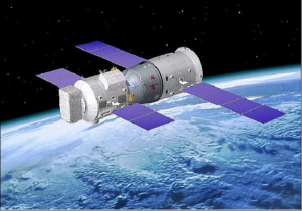
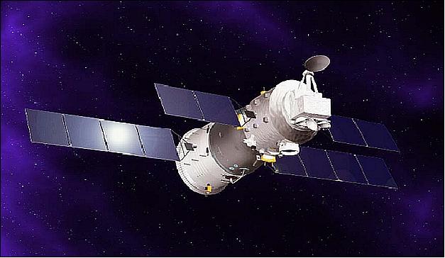
SZ (Shenzhou Spaceship)
Since 1999, four unmanned spacecraft SZ-1 (Shenzhou means “legend ship, or magic vessel” in Chinese) to SZ-4 have been launched successfully by CNSA (China National Space Agency). Onboard each spacecraft many research projects were performed. The research areas included space life science, space material, Earth observation, earth environment and space environment monitoring. Major contractors in the Shenzhou program were CASC (China Aerospace Science and Technology Corporation), the Chinese Research Institute of Space Technology, and the Shanghai Research Institute of Astronautical Technology.
Spacecraft | Launch date | Comment |
SZ-1 | Nov. 20, 1999 | First Chinese test launch for manned space flight (but without Taikonauts) from the Jiuquan Satellite Launch Center (JSLC) in northwestern China. After 14 orbits, the recovery capsule touched down in the Inner-Mongolia region of northwestern China on Nov. 21,1999 |
SZ-2 (China) | Jan. 9, 2001 | Second Chinese unmanned test launch from JSLC (launch mass of 7400 kg). It carried 64 science payloads. Orbit: 330 km x 346 km, inclination of 42.6º. Reentry capsule landing, Jan. 16, 2001. The orbital module remained in orbit conducting experiments. It reached a final orbit of 394 km x 405 km and was then allowed to decay. Reentry of orbiter module on Aug. 24, 2001. |
SZ-3 (China) | March 25, 2002 | Launch from JSLC. Reentry of SZ-3 on Nov. 12, 2002 over the southern hemisphere: impact at 22º S, 109º E (first long-duration unmanned flight; the orbital module disintegrated on reentry after nearly 232 days in orbit). |
SZ-4 (China) | Dec. 29, 2002 | Launch on CZ-2F launcher from JSLC. Seven day mission with a capsule landing on Jan. 5, 2003. The orbital module remained in orbit as in previous missions until June 2003. |
SZ-5 (China) | Oct. 15, 2003 | First Chinese manned flight on a CZ-2F launcher from JSLC (launch mass of 7790 kg, orbit: 332 km x 336 km, inclination of 42.4º). After 14 orbits the SZ-5 capsule landed successfully on Oct. 16, 2003. Liwei Yang became the first Chinese Taikonaut. The orbital module remained in orbit for a six month imaging mission. |
SZ-6 (China) | Oct. 12, 2005 | Second human spaceflight of China (2 Taikonauts) on a Long March 2F vehicle from JSLC (launch mass of ~ 8000 kg), orbit: 211 km x 345 km, inclination = 42.4º. Landing on Oct. 16, 2005 (5 day mission). |
SZ-7 (China) | Sept. 25, 2008 | The third mission had a crew of 3 Taikonauts. Launch on a CZ-2F launcher from JSLC. Orbit: 330 km x 336 km, inclination of 42.4º. First Chinese EVA (22 minute space walk) on Sept. 27, 2008. Landing on Sept. 28, 2008. |
Spacecraft
The SZ-3 and SZ-4 spacecraft, system test flights prior to manned spaceflight on SZ-5, carried also a sensor complement (technology demonstrations) in Earth observation (EO). This document deals mainly with two major EO instrument descriptions, namely CMODIS (Chinese Medium Resolution Spectral Imager) and CMMRS (China Multimode Microwave Remote Sensor) consisting of a radar altimeter, a microwave scatterometer and a microwave radiometer.
• The SZ-3 spacecraft had a launch mass of 7800 kg. Orbit: 374 km x 379 km, inclination of 42.4º. The crew module (with a dummy astronaut) returned to Earth on April 1, 2002 (after 6.78 days) with a landing in Inner Mongolia. The mission of the orbiter lasted until Nov. 12, 2002 (first unmanned long-duration flight) when the SZ-3 orbiter reentered Earth's atmosphere over the southern hemisphere (deorbited by the Beijing Space Command and Control Center). 1)
• SZ-4 orbit: altitude of 343 km, inclination of 42.4º. The SZ-4 carried a retrievable crew module with all furnishings, test equipment, and dummy astronauts to assess its viability for a manned launch. The crew module landed on Jan. 5, 2003 in Inner Mongolia (parachute landing, primary mission of 108 orbits, conducted by the Beijing Space Command and Control Center), while the orbiter of the SZ-4 spacecraft continued its observation mission in orbit.
Each SZ spacecraft consisted of a forward orbital module, a re-entry capsule, and an aft service module. Each S/C featured also a PDMS (Payload Data Management System) to satisfy the requirements of the payloads and experiments. The PDMS is a distributed system based on the 1553B data bus, consisting of the following elements: a bus controller, solid-state recorder, high-rate multiplexer, remote terminal, and S-band transmitter. All instruments up to 1 Mbit/s were connected to the system via 1553B data bus, the higher rate instruments had a serial connection to the high-rate multiplexer. All the data including video, imagery, science and housekeeping data, were encapsulated and interleaved according to the CCSDS standard protocols and downlinked in S-band. 2)
Sensor Complement
CMODIS (Chinese Moderate Resolution Imaging Spectroradiometer)
CMODIS is a Chinese medium-resolution ocean color instrument, designed and developed by SITP (Shanghai Institute of Physics and Technology). The instrument was first flown on the Shenzhou-3 (SZ-3) spaceship of CNSA (China National Space Agency) as a technology demonstration mission (launch March 25, 2002). 4) 5) 6)
CMODIS features a total 34 channels or bands, 30 channels of 20 nm wavelength in the spectral region of 0.403 to 1.043 µm (VIS), and four infrared channels in the regions: 2.15 - 2.25 µm (SWIR), 8.4 - 8.5 µm (TIR), 10.3 - 11.3 µm (TIR and 11.5 - 12.5 µm (TIR): The pushbroom instrument features 1024 pixels per line with a data quantization of 12 bits. Data from CMODIS is of high quality and can be used in inverse modelling to extract the concentrations of chlorophyll and suspended material.
On SZ-3, CMODIS orbited at a height of 343±5km above sea level (non-sun-synchronous orbit) with a ground resolution of 400-500 m, a 650-700 km swath width, and a repeat coverage of about 2 days in the South China Sea. The mission lasted until Nov. 12, 2002 when the SZ-3 module reentered Earth's atmosphere over the southern hemisphere. CMODIS stopped operating in September 2002, after 6 months of operation. CMODIS is considered a candidate instrument for a new generation of environmental satellites of CNSA. 7) 8)
Parameter | VIS (Visible region of spectrum) | SWIR (Short Wave Infrared) region | TIR (Thermal Infrared) region |
Spectral range | 403-803 nm (20 bands) | 2.15-2.25 µm (1 band) | 8.4-8.5, 10.3-11.3, 11.5-12.5 µm (3 bands) |
Wavelength | 20 nm | 0.1 µm | 0.5, 1.0, 1.0 µm |
FOV (Field of View) | ±44º (700 km swath) | Spatial resolution | 400 m (at nadir) |
Data rate | 7.2 Mbit/s | Data quantization | 12 bit |
China Multimode Microwave Remote Sensor
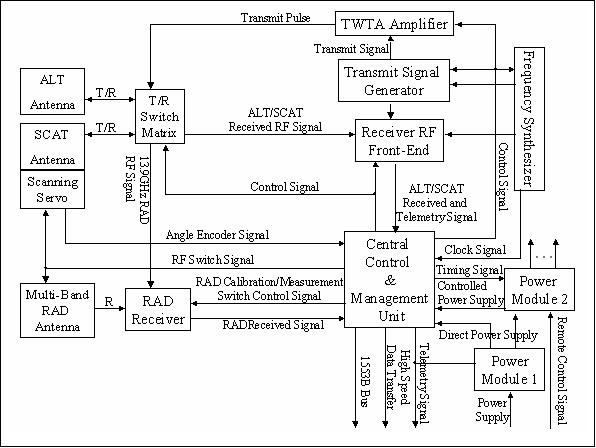
CMMRS is an integrated microwave instrument demonstration package on SZ-4, consisting of two active sensors, namely ALT (Altimeter) and SCAT (Scatterometer), and RAD (Radiometer), a passive instrument. CMMRS was designed and developed at CSSAR (Center for Space Science and Applied Research), Beijing. CMMRS is China's first spaceborne microwave remote sensing system. Note: CMMRS is also being referred to in the literature as M3RS (Multiple Model Microwave Remote Sensor). 9)
The prime objective of CMMRS observations is in support of ocean research, atmospheric research, and soil moisture monitoring applications. CMMRS onboard SZ-4 is an experimental system for technology validation. The CMMRS observations on SZ-4 extended over a period of three months (as planned), starting on Jan. 2, 2003. 10) 11) 12) 13) 14)
The CMMRS instrument can be used in such applications as sea surface, land surface, and atmospheric observations. Specific acceptance objectives are:
• Validation of the new observation scheme provided by CMMRS
• Functional validation of the various operating modes of CMMRS
• Validation of the measurement data quality
• Use of the data in various applications and test of the models and algorithms employed
• Technological preparation for China's ocean remote sensing satellite (HY-2 series, a first launch is planned for 2011) using a microwave sensor payload.
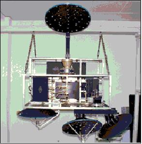
The CMMRS is modular allowing various configuration allocations depending on observational requirements of a mission. The CMMRS instrument design employs a common antenna unit for the five-band radiometer (RAD) with multi-feeder systems, and with two conical scanning pencil-beam antennas for Scattermeter (SCAT), using an incidence angle of 37º, and with a nadir-looking antenna for the Altimeter (ALT). The mass of the entire system is <140 kg. The CMMRS design benefits from airborne instruments flown in the Chinese EO program since the 1980s. 15)
CMMRS offers the following operational support modes:
• ALT + RAD
• SCAT + RAD
• RAD only
• SCAT only
• ALT only
1) ALT is a single-frequency altimeter instrument operating in Ku-band. The instrument features a SAW dispersive chirp generator and shares the TWT (Travelling Wave Tube) amplifier with SCAT. The ALT instrument provides measurements in support for the geoid studies, average sea surface height, SWH (Significant Wave Height) and sea surface wind speed.
Sea surface height precision | <= 10 cm (after atmospheric correction and orbit error correction) |
Range of SWH measurements | 1 - 20 m |
SWH precision | 0.5 m or 10% |
Backscattering coefficinet precision | ± 1 dB (sigma naught) |
Center frequency of ALT | 13.9 GHz (Ku-band) |
Antenna pointing precision | 0.5~1º |
2) SCAT of CMMRS, also referred to as CNSCAT (China ScanSCAT). CNSCAT is a Ku-band, dual-polarization, two pencil-beam, and conically scanned scatterometer. The two pencil beams (two antennas) are placed perpendicularly in the azimuth direction. A conically-scanned system has advantages, such as low transmitted power requirement, a wide swath width, and a simple system configuration (much smaller antennas), as compared to fan beam scatterometers. In addition, a conically scanned antenna system is much easier to calibrate.
SCAT includes the following main elements: antenna, transmitter and frequency synthesizer, receiver, data processing and control unit. The objective of SCAT is to provide measurements for wind field retrievals (speed and direction) at the ocean surface.
In CNSCAT operation, H and V polarization is being switched sequentially, thereby obtaining four different measurements of the backscattering coefficient (sigma naught) in each measurement cell [both VV and HH sigma-zero measurements are obtained at two azimuth locations]. The wind vector is being retrieved by solving the equations of these four measurements. CNSCAT produces rosette-shaped footprints (19 km x 24 km of 3 dB footprint) due to the conical scanning motion of the antennas in the flight direction of the spacecraft.
Wind speed range measurements | 4 ~ 24 m/s |
Wind speed precision | 2 m/s or 10% |
Wind direction range | 0 - 360º |
Wind direction precision | ±20º |
Dynamic range of backscattering coefficient | -40 dB to about +20 dB |
Backscattering coefficient precision | ± 0.5 dB |
Swath width | 350 km |
Spatial resolution | 50 km |
Polarization | VV and HH |
ALT | SCAT | ||
Center Frequency | 13.9 GHz (Ku-band) | Center frequency | 13.9 GHz (Ku-band) |
Peak power | 57 W | Peak power | 100 W |
Pulse width | 24 µs | Pulse width | 0.65 ms |
Chirp bandwidth | 333 MHz |
|
|
Antenna gain (2-way) | 69 dBi | Antenna gain (2-way) | 69 dBi |
PRF | 1.23 kHz | PRF | 128 Hz |
Receive noise figure | 5.5 dB | System noise temperature | 420 K |
Final SNR | 10 dB | SNR | 40.97 dB |
3) RAD is a passive multifrequency (5 frequency, 8-channel) total-power type radiometer. Its observations are being used for the retrieval of: sea surface brightness temparature, rainfall, , vapor content, soil moisture, snow, etc. RAD measured the microwave brightness temperature at five frequencies with dual polarizations at three frequencies (6.6, 19.35, and 37.0 GHz) and with only vertical polarizations at two frequencies (13.9, 23.8 GHz). The 13.9 GHz frequency channel of RAD uses the same antenna with the Ku-band scatterometer (CNSCAT), its incidence angle is 39.4º. The RAD antenna (at other frequencies than 13.9 GHz) scans at a fixed incidence angle of 42.6º in a circular orbit of 343 km altitude, providing an observation coverage between the latitudes of ±42º. The spatial resolution at the surface varies from approximately 32 km at 6.6 GHz to 6 km at 37 GHz. The SZ-4 radiometer data combines with radar altimeter and scatterometer data. The three kinds of microwave instruments form a combined observation method and can obtain different remote sensing observation parameters from a same observation zone. 16) 17)
Brightness temperature precision | 1.0 K |
Dynamic range of brightness temperature | 100 ~330 K |
Wind speed range | 10~50 m/s |
Incidence angle | 40º |
The RAD antenna is an offset parabolic reflector with a multifrequency feed. Since RAD lacks an on-orbit external calibration, a vicarious external calibration scheme was devised. All RAD channels were re-calibrated by using typical microwave emission targets on land, the global open ocean, and the Amazon rain forest. The re-calibrated brightness temperatures of RAD were compared with in situ measurements obtained during the ground experiment carried out in February, 2003.
The RAD observation data are being used to retrieve the temperature and vapor profile, the water content of the atmosphere, and in applications of ocean surface temperature retrieval.
Center frequency (GHz) | 6.6 | 19.35 | 23.8 | 37 | 13.9 |
Antenna type | Offset Feed Paraboloidal Reflector Antenna | Dual Paraboloidal Reflector | |||
Antenna diameter | 760 mm | 600 mm | |||
IFOV (beam width) | 5.3º | 1.81º | 1.57º | 0.94º | 2.60º |
Antenna gain (dB) | 29.3 | >30 | >30 | >30 | >37 |
Brigthness temperature (BT) | 100~300 K | 100~330 K | 100~330 K | 100~330 K | 100~330 K |
BT sensitivity | ±0.26 K | ±0.29 K | ±0.42 K | ±0.43 K | ±0.18 K |
Main beam efficiency (%) | 85 | 86 | 86 | 88 | 89 |
Pixel size (km x km) | 32 | 11 | 8 | 6 | 16 |
RF bandwidth (MHz) | 400 | 400 | 400 | 800 | 600 |
IF bandwidth (MHz) | 200 | 200 | 200 | 400 | 200 |
Integration time (ms) | 100 | 100 | 100 | 100 | 100 |
Results: During its operational period of 3 months (until March 28, 2003), the CMMRS instruments of RAD, ALT, and SCAT acquired data of 690.5 h, 130.8 h and 2.7 h, respectively. The volumes of the measurement data for these three instruments are: 1.0 GB, 1.9 GB and 50 MB, respectively. The scan mechanism of SCAT experienced an early failure resulting in a very small operating period.
The data acquired with CMMRS plays an important role in the study of wind fields, ocean wave dynamics and the exchange of ocean-atmosphere energy, as well as analysis of ocean disasters and fishery resources. The successful mission of the Shenzhou spacecraft has laid a firm foundation for the future development of the SZ series and enhanced the capacity of Earth observation from the space.
References
1) http://www.astronautix.com/craft/shenzhou.htm
2) H. X. Sun, X. M. Chen, “Payload Data Management System for Chinese Unmanned Spacecraft Shenzhou,” Proceedings of IAC 2003, Bremen, Germany, Sept. 29 - Oct. 3, 2003, IAC-03-U.4.06
3) Shenzhou-7 Mission and Beyond ---- from Imagination to Reality,” URL: http://www.thespacereview.com/archive/1565b.pdf
4) H. Guo, W. Wang, C. Wang, R. Zhong, B. Zhu, J. Chen, “Environmental Monitoring with Remote Sensing Data from Chinese Spacecraft,” Proceedings of IGARSS 2004, Anchorage, AK, USA, Sept. 20-24, 2004
5) J. Tong, K. Qiu, X. Li, “Radiometric Cross-calibration of the SZ3-CMODIS and EOS-MODIS in the Visible and Near-infrared Spectral Bands By Using Two Targets in the Images, “ Proceedings of IGARSS 2004, Anchorage, AK, USA, Sept. 20-24, 2004
6) J. Chen, Y. Shao, H. Guo, W. Wang, and B. Zhu, “Destriping CMODIS Data by Power Filtering,” IEEE Transactions on Geoscience and Remote Sensing, Vol 41, No 9, Sept 2003, pp 2119-2124
7) P. Delu, “Chinese Ocean Color Program (CMODIS, COCTS, CZI),” Minutes of the Ninth IOCCG (International Ocean-Color Coordinating Group) Committee Meeting, January 15-17, 2004, Hyderabad, India, http://www.the-eggs.org/articles.php?id=48
8) Zhihua Mao, Delu Pan, Haiqing Huang, “Evaluation of the CMODIS-measured radiance,” Proceedings of SPIE, 'Remote Sensing of the Marine Environment,' Editors: Robert J. Frouin; Vijay K. Agarwal; Hiroshi Kawamura; Shailesh Nayak; Delu Pan, Volume 6406, Nov. 20, 2006, ISBN: 9780819465139
9) M. Lin, X. Jiang, “An Achievements and Limitations Evaluation on M3RS Measurement System,” Proceedings of the 26th ACRS (Asian Conference on Remote Sensing), Hanoi, Vietnam, Nov. 7-11, 2005
10) J.-S. Jiang, H. Liu, X. Dong, “The China Multimode Microwave Remote Sensor (CMMRS) on-board the SZ-4 Spaceship,” CSSAR Report presented in Korea, May, 2004
11) H. Liu, J. Jiang, X. Dong, J. Li, K. Xu, “China Advanced Microwave Remote Sensor ,” Proceedings of ACRS (Asian Conference on Remote Sensing), Kong Kong, China, Nov. 22-25, 1999, URL: http://www.a-a-r-s.org/acrs/proceeding/ACRS1999/Papers/PS299-19.htm
12) J.-S. Jiang, Z.-F. Zheng, H.-G. Liu, X.-Z. Wang, Y.-H. Zhang, J. Huang, “China Advanced Microwave Remote Sensor (CAMRS),” Space Technology, Vol. 18, No 1/2, 1998, pp. 57-63, Elsevier Science Ltd, PII:S0892-9270(98)00002-5
13) Information provided by Zhenzhan Wang of CSSAR, Beijing
14) X. Dong , S. Zhu, D. Zhang, Bo Sun, H. Liu, J.-S. Jiang , “The design and implementation of the scatterometer of China Advanced Microwave Remote Sensor,” Proceedings of IGARSS 2000, Honolulu, HI, July 24-28, 2000
15) J.-S. Jiang, Y. Zhang, X. Dong, J. Huang, “A Chinese Spaceborne Scanning Scatterometer (CNSCAT) Design,” Photogrammetric Engineering & Remote Sensing, ASPRS, Vol. 66, No 5, May 2000, pp. 5999-604
16) R. Zhong, H. Guo, W. Wang, B. Zhu, “Performance Evaluation of Microwave Radiometer Carried by Shenzhou IV for Land Surface Parameters Retrieval,” Proceedings of IGARSS 2004, Anchorage, AK, USA, Sept. 20-24, 2004
17) Z. Z. Wang, “Analysis and Calibration of Microwave Radiometer (RAD) on-board SZ-4 Spacecraft,” Proceedings of IGARSS 2004, Anchorage, AK, USA, Sept. 20-24, 2004
The information compiled and edited in this article was provided by Herbert J. Kramer from his documentation of: ”Observation of the Earth and Its Environment: Survey of Missions and Sensors” (Springer Verlag) as well as many other sources after the publication of the 4th edition in 2002. - Comments and corrections to this article are always welcome for further updates (eoportal@symbios.space).