SERVIS (Space Environment Reliability Verification Integrated System)
Technology Development
SERVIS (Space Environment Reliability Verification Integrated System)
SERVIS is a Japanese technology demonstration program (2 missions) with the overall objective to utilize state-of-the-art COTS (Commercial Off-The-Shelf) components and technology in space. SERVIS is being developed by Japan's institute of USEF (Unmanned Space Experiment Free Flyer) of Tokyo under a contract from NEDO (New Energy and Industrial Technology Development Organization), and METI (Ministry of Economy, Trade and Industry).
As part of the SERVIS project, the COTS components are being subjected to various ground evaluation tests, including radiation tolerance tests. Those parts that survive the screening process, will be verified in the space environment on two SERVIS satellites. The ground evaluation results will be compared with their performance in space. It is expected that the use of space-validated COTS components will provide some guidelines and result in considerable cost reductions for future satellites. 1) 2) 3) 4) 5) 6) 7)
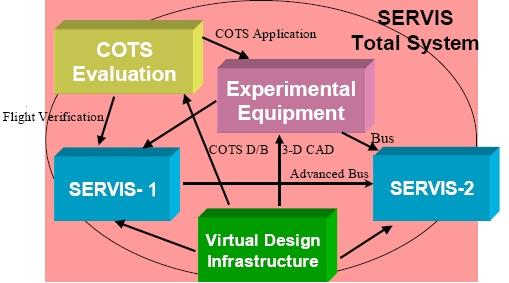
The program is comprised of four segments:
• Ground evaluation test for various COTS, including radiation tolerance tests. The ground tests consist of screening tests, radiation tolerance tests, and quality conformance inspection - all are based on MIL-STD-883.
• Development and space verification of advanced COTS applied experimental equipment
• Development of two verification satellites
• Development of network design infrastructure.
The SERVIS project has started in 1999 and is ongoing in 2011. During this period, two verification satellites were developed. The first satellite was already launched in October, 2003 and its two year on-orbit operation was successfully completed. The second satellite was launched in June 2010 and also successfully completed its operation in June 2011.
SERVIS-1 Spacecraft
The basic design of the SERVIS-1 bus is a heritage design of the Service Module (SEM) of USERS (Unmanned Space Experiment Recovery System). SERVIS-1 was manufactured at MELCO (Mitsubishi Electric Corporation).
Note: The USERS spacecraft was launched on Sept. 10, 2002 on an H-IIA launcher from the Tanegashima Space Center, Japan. The primary payload on the flight was DRTS (Data Relay Technology Satellite) of JAXA. USERS was in an orbit of 500-600 km altitude with an inclination of 30º. The operations of USERS-1 were terminated on Feb. 25, 2005.
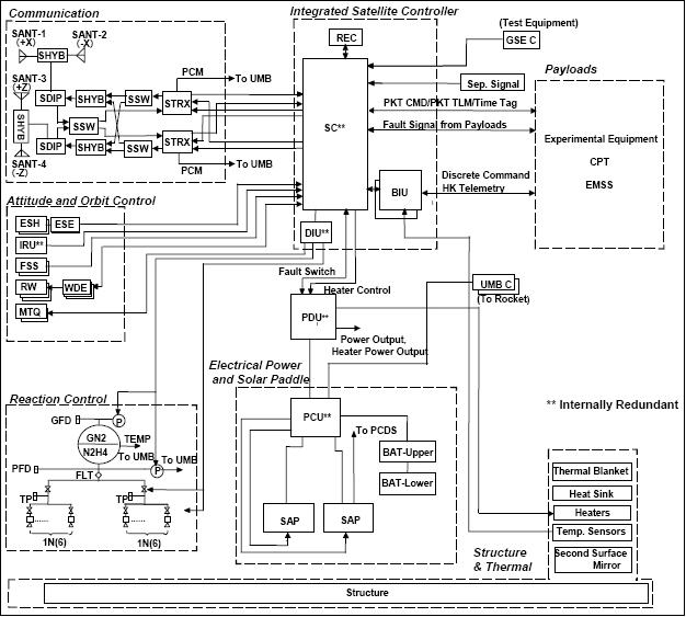
Spacecraft mass | 840 kg |
Spacecraft size | Cubic structure of 2 m side length |
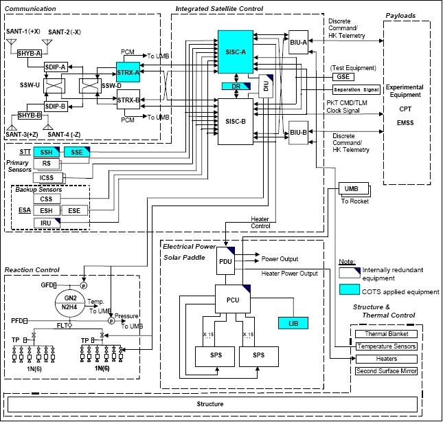
Spacecraft control | Centralized control by ICS (Integrated Satellite Controller) |
Attitude control | 3-axis stabilized |
Electric power generation | > 1300 W (the two solar arrays extend to a length of 10.2 m) |
Power supply voltage | 50 V, floating bus system |
RF communications | S-band: downlink: USB (2 kbit/s), HSB (256 kbit/s); Uplink: 4 kbit/s; |
Propulsion subsystem | Monopropellant hydrazine system, thruster: 1N |
Payload resources | Mass: > 300 kg |
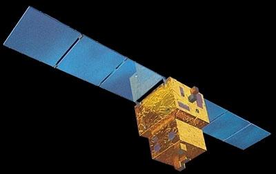
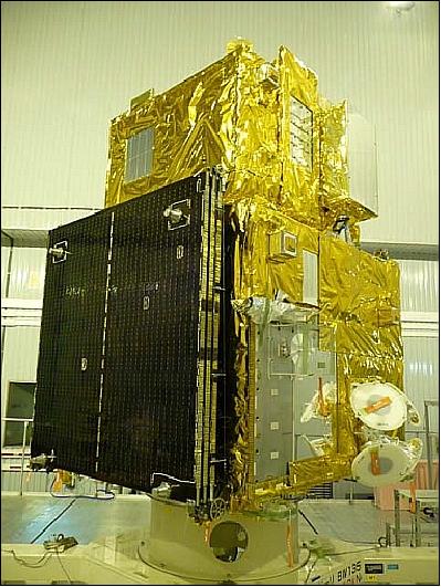
![Figure 2: Photo of the SERVIS-1 spacecraft [bus module and payload module (top)], image credit: USEF](/api/cms/documents/163813/205575/Servis_AutoB.jpg/ecee1be2-2e2a-4fb8-bc95-5efb7edfceef?t=1339604577000)
The SERVIS ground operation and control system is comprised of the USEF Space Operations Center (USOC) and the ground tracking stations. USOC is located in the metropolitan area of Tokyo. The new ground network of JAXA is used for SERVIS operations.
Launch
A launch of SERVIS-1 took place on Oct. 30, 2003 on a Rockot launch vehicle of Eurockot Launch Services (Bremen) from Plesetsk, Russia.
Orbit: Sun-synchronous circular dawn/dusk orbit, altitude = 1000 km , inclination = 99.5º.
SERVIS-1 Mission Status
The two-year on-orbit verification test by SERVIS-1 was successfully completed on Nov. 1, 2005. All of the experimental equipment had continued flawless operation and well cleared extra success level criteria of the verification test. The data from the payloads are being analyzed. in post-flight processing.
• After orbit injection, the spacecraft was subjected to bus checkout, followed by experimental equipment checkout.
• The actual verification test started on 26 November, 2003. Start of medium-range operations plan of 16 weeks. This was followed by successive 8 week operations periods.
Sensor/Experiment Complement of SERVIS-1 (CPT, LPD)
One of the most important tasks of the SERVIS project is to select the proper COTS devices and to evaluate their performance from the standpoint of space applicability. During the project period, about 200 COTS devices are to be verified for space application. In selecting the COTS parts, the following guidelines are applied:
• The emphasis is on state-of-the-art technology selection, high performance devices such as CPUs, GAs and memories rather than conventional discrete parts.
• Design advanced, high performance bus equipment and then select COTS equipment necessary to realize the applications.
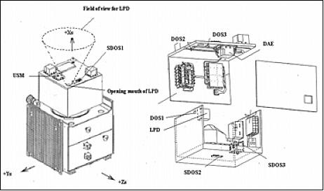
The EMS (Environment Monitor System) onboard the SERVIS-1 spacecraft consists of the LPD (Light Particle Detector), two single event USM (Upset Monitors), three DOS and three SDOS (Shield Dose Monitors).
CPT (Commercial Parts Test)
The CPT unit is onboard the SERVIS satellite to evaluate COTS parts performance under spaceborne conditions.
Item | Electrical parts | Technology | Electrical part type | Technology name |
VTS (Vane-type propellant Tank System) | 1 | 1 | Void Sensor | Super Plastic |
INU (Integrated Navigation Unit) | 1 | 0 | RF device in GPS receiver | - |
PDCS (Power Control & Distribution Unit) | 1 | 0 | CPU (16 bit) | - |
APDM (Advanced Paddle Drive Mechanism) | 0 | 1 | - | Grease lubricant |
ATTC (Advanced TT&C Transponder) | 11 | 1 | 16b D/A C, 12b A/D C, |
Surface Mount |
OBC (OnBoard Computer) | 6 | 1 | 32 bit CPU, SDRAM, FPGA, | Multi-chip |
SIS (Integrated Satellite Controller with Star Sensor) | 4 | 1 | 32 bit CPU, EEPROM, CCD, SDRAM | Surface Mount |
LIB (Lithium Ion (Co type) Battery System) | 0 | 3 | - | Battery Cell (50AH), Power Hybrid IC |
FOIRU (Fiber Optic Gyro Inertial Reference Unit) | 5 | 0 | Super luminescent diode, |
- |
Total | 29 | 7 | - | - |
Item | SERVIS-1 | SERVIS-2 |
SRAM (Static Random Access Memory) | 1Mbit, 4Mbit | 4 Mbit, 8 Mbit |
DRAM (Dynamic Random Access Memory) | 128 Mbit, 256 Mbit | 256 Mbit, 512 Mbit |
SOI SRAM (Silicon-On-Insulator) | 256 Mbit, 0.35 µm | 128 kbit, 0.18 µm |
Flash memory | NOR type, 32 Mbit | NOR type, 128 Mbit |
FPGA (Floating Point Gate Array) | SRAM type, EEPROM type | SRAM type, EEPROM type |
Table 4 shows the frequency of SEUs (Single Event Upsets) observed for COTS components in orbit, in comparison with the predicted frequency as a result of ground radiation tolerance test. As shown in the table, the actual frequency of SEUs observed on orbit was far less than the predicted frequency using ground test results. The table also reveals that a better match between ground test and orbit result is observed for proton than for heavy ion, thus proving the concept that proton has the dominant effect for SEU for equipment in LEO (Low Earth Orbit).
SIS (Satellite Controller Integrated with Star Sensor) is developed as a prototype model of a compact low cost satellite controller. SIS integrates attitude sensors into a star sensor and integrates several electronics for star identification, attitude determination, attitude control, and data handling into a single processing unit. 9)
Item | Part's type | SEU (times) | |
Predicted values by heavy ion irradiation test | Measured values | ||
OBC | 32 bit CPU | 4.2/day | 0.16/day |
SIS | 32 bit CPU | 0.23/day | 0.08/day |
ATTC | 16 bit DAC | 0.8/day | 0.06/day |
PCDS | 16 bit CPU | 2.3*/year | 1.5/year |
CPT | 1 M SRAM | 1.0 or 2.1*/day | 0.79/day |
LPD (Light Particle Detector)
The objective is to measure the space radiation environment. LPD is an energetic particle spectrometer of PSI (Physical Sciences Inc., Andover, MA, USA), with a flexible energy range, for characterizing the space environment in the presence of the LWS-SET spacecraft. The instrument detects and energy-analyzes protons (1 to 150 MeV), electrons (0.3 to 10 MeV), alpha particles (7 to 640 MeV), and heavy ions (2 to 30 MeV/nucleon). 10) 11)
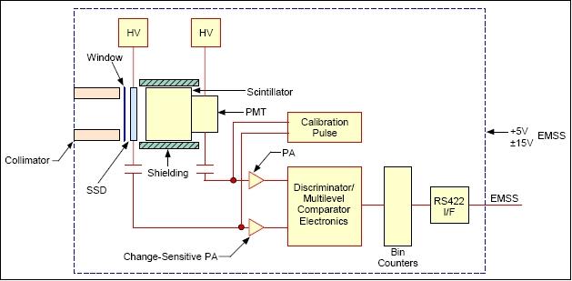
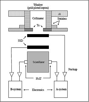
The SERVIS-1 LPD detection system is based on SSD (Solid-state Silicon Detector) technology and inorganic scintillators coupled to state-of-the-art analog and digital electronics. The detection system comprises a single 500 µm thick, fully-depleted, SSD backed by a 24 mm thick YAP (Yttrium Aluminum Perovskite) scintillator. YAP scintillators are relatively high-Z and have a excellent stopping power for electrons. They also exhibit an almost negligible temperature coefficient up to very high temperatures. Hamamatsu metal dynode PMTs (Photomultiplier Tubes) detect the scintillator photons. These PMTs have been used previously for spaceborne scintillator detectors.
A collimator defines the acceptance angle and an aluminum and gold plated kapton window rejects visible photons and low energy charged particles. The SSD and PMT signals are amplified by high-speed, ultra low noise charge sensitive preamps. The shaped preamp outputs are fed into a peak-hold hybrid circuit and digitized by a 12-bit ADC system. The digitized values are input to a radiation-tolerant Actel RT54SX32 FPGA that handles all the onboard signal processing, health monitoring, and telemetry.
Protons | 1.2 - 150 MeV (6 bins) |
Energy resolution | dE/E = 0.25 FWHM (Full Width Half Maximum) |
Count rate | 200,000 particles/s |
G-factor | 0.2 cm2 sr |
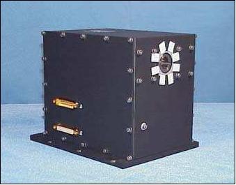
Instrument mass, power | 4.2 kg, 2 W |
Instrument size | 120 mm x 120 mm x 150 mm |
Since the LPD is considered a component of the spacecraft bus, it is an integral part of the measurement of the on-orbit radiation environment central to the mission success, it has completely redundant systems.
Technical Knowledge Base
The objective of the SERVIS program is the provision of a technical knowledge base, consisting of a group of documents to indicate the way to use COTS parts in space applications through extensive ground evaluation tests and orbit verification tests. The documents are now being assembled and updated, but will be finally completed after SERVIS-2 orbit verification test is completed.
SERVIS-2 Mission
The SERVIS-2 spacecraft uses the same spacecraft bus as SERVICE-1 with a total mass of about 740 kg. The spacecraft is 3-axis stabilized. The star sensor of SERVIS-1 with redesigned baffles is planned to be installed as the main attitude sensor for the SERVIS-2 satellite. A mission life of 1 year is planned. 12)
Note: The SERVIS-2 spacecraft is not simply recurring but upgrading of SERVIS-1, because some of the experimental equipment verified on SERVIS-1 was adopted as SERVIS-2 bus. Eventually, ATTC (Advanced TT&C Transponder), LIB (Li-Ion Battery) system, and SIS (Satellite Controller Integrated with Star Sensors), which had been on-board of SERVIS-1 as experimental equipment, was selected for the SERVIS-2 bus. The orbital altitude of SERVIS-2 was designed 200 km higher than that of SERVIS-1 so that the same TID might be expected for shorter mission durations. 13)
Launch
The SERVIS-2 spacecraft was launched on June 2, 2010 by the Rockot-KM launch vehicle of Eurockot Launch Services GmbH (Bremen) from Plesetsk, Russia (a launch contract was signed in Feb. 2007). 14)
Orbit: Sun-synchronous circular dawn/dusk orbit, altitude = 1200 km , inclination = 100.4º.
The two verification spacecraft have been developed not only for the space verification of the COTS payloads such as experimental equipment and CPT (Commercial Parts Test) unit, but also for the technology acquisition of low cost LEO bus in the future. The SERVIS spacecraft system summary is shown in Table 6.
Item | SERVIS-1 | SERVIS-2 |
Launch date | Oct. 30, 2003 | June 2, 2010 |
Launch vehicle | Rockot-KM | |
Operational orbit | Altitude = 1000 km, inclination = 99.5º | Altitude = 1200 km, inclination = 100.4º |
Mission duration | 2 years | 1 year |
Spacecraft mass | 840 kg | 740 kg |
Spacecraft size | 2.5 m (H) x 10.2 m (L) | |
Generated power | > 1300 W | |
Spacecraft control | Centralized control by Integrated Spacecraft Controller | |
Attitude control | 3-axis stabilization | |
Power supply | 50 V floating bus system | |
NiH2 battery | Li-ion battery | |
Data handling | CCSDS Recommendation based Packet | |
RF communications | Telemetry: USB (2 kbit/s), HSB (256 kbit/s); Command: 4 kbit/s | |
Propulsion | Mono Propellant Hydrazine System; Thruster: 1 N | |
Spacecraft operation | USOC (USEF Space Operations Center) | |
Ground stations | JAXA Ground Network (GN) | |
Resources for payload | Mass: >300 kg, Power: >500 W, Date Rate: > 2400 bit/s | |
Mission Status
• On June 3, 2011, the on-orbit operation was terminated, with all experimental payloads operating nominally and with all data acquired for space verification. The experimental equipment has experienced SEUs and SELs because COTS are embedded in the equipment (Ref. 13).
The experimental payloads on-board of SERVIS-2 have worked well and achieved the full success level of the space verification.
• Just after the checkout of SERVIS-2, the verification test of experimental payloads was started on June 19, 2010 and continued for about 1 year.
• After the critical phase had finished, SERVIS-2 was subjected to the bus checkout, followed by the experimental payloads checkout. The whole checkout period of SERVIS-2 was 10 days shorter than that of SERVIS-1, reflecting the experience of the former spacecraft.
• SERVIS-2 was precisely injected into the planned orbit. Just after the separation from Rockot, solar array paddles were deployed and 3-axis acquisition was successfully completed with its main Star Sensor Integrated Spacecraft Controller (SISC-A) which was developed as the bus controller based on the experimental equipment of SERVIS-1.
Sensor/Experiment Complement of SERVIS-2
SERVIS-2 will mount 9 experimental equipment with various COTS components. In addition, RF-MEMS experimental equipment was added as one of the payloads to SERVIS-2.
Item | Electrical parts | Technology | Electrical part type | Technology name |
LIBA [Lithium Ion (Mn type) Battery System] | 7 | 1 | 32 bit CPU, Multiplexer, Photo-coupler, Relay driver, MOS-FET, OPAmp. Hole Sensor | Battery Cells |
ADMS (Advanced Data Management System) | 17 | 0 | 32 bit CPU, Flash memory, SRAM, FPGA, FET, Digital IC×6, Analog IC×4, Transistor×2 | - |
CRAFT (64 bit Autonomous Fault Tolerant Computer) | 4 | 0 | 64bit MPU, 64bit MPU (BGA), SRAM, SDRAM | - |
PPRTU (Plug-and-Play Remote Terminal Unit) | 9 | 0 | IEEE-1394 I/F LSI, PLL LSI, LVDS, Line Driver, LVDS Line Receiver, PCI I/F device, Dual port SRAM, High speed FIFO, EDAC, Buffer IC | - |
HPDC (High Performance Data Compressor) | 7 | 2 | LVD Line Driver, LVDS Line | Multi-chip Module, |
APE (Advanced Position Detection Experiment) | 4 | 2 | OPAmp., FIFO, FPGA, SDRAM, | GPS Receiver, Mounting Technology |
ASM (Advanced Satellite Structure Module) | 7 | 1 | 32 bit CPU, FPGA, Driver x 2, OPAmp., EEPROM, SDRAM, | Mounting Technology |
MBW (High Performance Magnetic Bearing Wheel) | 1 | 1 | Power MOSFET | Magnetic Bearing |
MEMS (RF-MEMS Experiment Unit) | 1 | 1 | RF-MEMS Switch | MEMS Manufacturing Process |
Total | 57 | 8 |
|
|
Technical Knowledge Bases
Technical knowledge bases are the ultimate products of the SERVIS project. They are groups of documents to indicate the way to use COTS for space application through extensive ground evaluation test and space verification test. These documents have been assembled and updated after SERVIS-2 orbit verification test.
The COTS Database contains the result of ground evaluation test, especially that of radiation tolerance test. By this database, one can learn to what extent certain COTS parts can withstand to the space environment, thus to give the criteria in using that particular COTS for space application.
Considering the criticality of COTS information to be used for space application, the database has a two-tier structure. Namely, the first tier contains limited information open to the public, while the second tier has more detailed and specific information. The first tier database consists of general information such as COTS ID number (assigned by USEF), general specification, summary of radiation test, and summary of quality conformance test. The second tier and detailed database is restricted to the relevant personnel only and contains following information.
1) Parts number
2) Name of manufacturer
3) Specification
4) Screening test condition and its result
5) Radiation test condition and its result
6) Quality conformance test and its result.
The reason for this two tier structure comes from the consideration towards COTS parts manufacturer whose products are not originally intended to be used for space application. However, if a Japanese potential user is interested in certain COTS parts by reviewing the first tier database, one can contact USEF for more detailed information and would be able to contact with the parts manufacturer for detailed discussion.
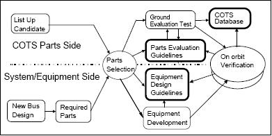
During the project period, over 200 devices of COTS were selected and evaluated on ground, from the standpoint of space applicability. And those COTS which passed the criteria at the ground evaluation test are verified under the space environment using two SERVIS spacecraft. The results of ground and space evaluation tests are evaluated and correlated, and assembled into following three technical knowledge bases.
• COTS Database: This is a database which contains the COTS ground test results including radiation tolerance data.
• COTS Evaluation Guideline: This is a guideline for the ground test and parts selection which enable to judge COTS space applicability without further space verification test for COTS in the future.
• Equipment Design Guideline: This is a guideline for space-borne equipment design which contains recommendations and precautions on how to use COTS for spacecraft equipment.
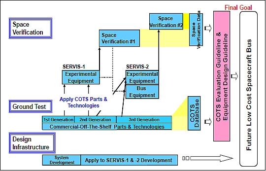
The task flow of the project is shown in Fig. 1. As indicated in Fig. 1, three generation’s COTS have been ground tested and on-orbit tested to find out relationship between COTS design rule difference by generation and radiation tolerance performance. It also shows that the final goal is to establish technical knowledge bases, which enable Japanese space industry to have low cost spacecraft bus in the future.
References
1) http://www.usef.or.jp/english/f3_project/servis/f3_servis.html
2) H. Kanai, K. Hama, M. Akiyama, N. Natsuka, “SERVIS-1 COTS Technical Knowledge Bases for Space Application,” Proceedings of the 57th IAC/IAF/IAA (International Astronautical Congress), Valencia, Spain, Oct. 2-6, 2006, IAC-06-D1.P.2.04
3) H. Kanai, K. Hama, M. Akiyama, Y. Hanawa, “SERVIS Project: Application of commercial Technology for Space,” Proceedings of the 55th IAC, Vancouver, Canada, Oct. 4-8, 2004, IAC-04-U.2.01
4) H. Kanai, K. Hama, M. Akiyama, N. Oka, S. Matuoka, “SERVIS: A Project for Commercialization of Space Industry,” 52nd IAC (International Aeronautical Conference), Toulouse, France, Oct. 1-5, 2001, IAA-01-IAA.1.2.08,
5) H. Kanai, K. Hama, M. Akiyama, N. Natsuka, “Overview of SERVIS Project toward Application of Commercial Technology for Space,” Proceedings of IAC, Fukuoka, Japan, 2005, IAC-05-D1.2.09
6) M. Hareyama, M. Asaeda, M. Fujii, N. Hasebe, N. Kajiwara, S. Kodaira, K. Sakurai, M. Akiyama, K. Ichiji, K. Hama, “Particle monitors to survey radiation environment in the radiation belts onboard Japanese satellites, USERS and SERVIS-1,” 29th International Cosmic Ray Conference Pune, India, Aug. 3-6, 2005, URL: http://www.ast.leeds.ac.uk/~jh/ICRC/PAPERS/SH16/jap-hareyama-M-abs2-sh16-poster.pdf
7) Hiroshi Kanai, Kazumori Hama, Masatsugu Akiyama, Osamu Itoh, “COTS Parts Evaluation in SERVIS Project,” The 20th Microelectronics Workshop, Tsukuba, Japan, Oct. 30, 2007, URL: https://eeepitnl.tksc.jaxa.jp/mews/en/20th/data/1_05.pdf
8) Naoki Shibayama, Nobuko Akazawa, Masahiro Koyama, Shinichi Miyagawa, Tetsumasa Ito, Kazuto Kaminogo, “Space Verification of On-Board Computer Integrated with Commercial IC,” Mitsubishi Heavy Industries, Ltd., Technical Review Vol. 42 No. 5 (Dec. 2005), URL: http://www.mhi.co.jp/technology/review/pdf/e425/e425242.pdf
9) P. Buist, S. Kumagai, K. Hama, “GPS-based Attitude Determination in Different Attitude Modes: Experimenting with a GPS Receiver and a Star Sensor onboard the SERVIS-1 Satellite,” Proceedings of the 6th International ESA Conference on Guidance, Navigation and Control Systems,” Loutraki, Greece, Oct. 17-20, 2005, SP-606, January 2006
10) G. E. Galica, B. D. Green, T. Nakamura, H. Kikuchi, T. Ogawa, Y. Sasaki, M. Akiyama, K. Hama, “SERVIS LPD Energetic Charged Particle Spectrometer,” 40th AIAA Aerospace Sciences Meeting and Exhibit, Jan. 14-17, 2002,Reno, NV, USA, AIAA-2002-0939
11) G. E. Galica, B. D. Green, T. Nakamura, H. Hasegawa, T. Ithoh, Y. Sasaki, H. Kanai, M. Akiyama, K. Hama, “Energetic Charged Particle Spectrometer for the Space Environment Reliability Verification Integrated System (SERVIS-1) Satellite, IEEE Nuclear and Space Radiation Effects Conference, Atlanta, GA, USA, July 19-23, 2004, URL: https://web.archive.org/web/20101127000305/http://www.psicorp.com/pdf/library/VG04-190.pdf
12) H. Kawano, H. Shimoji, S. Yoshikawa, K. Miyatake, K. Hama, S. Nakamura, “Solar-light shielding using a near-hemispherical lens for a star sensor,” SPIE, Optical Engineering, Vol. 45, Dec. 2006, Issue 12, 124403
13) Noriaki Oka, Koichi Ijichi, Kazumori Hama, Masatsugu Akiyama, Hideyuki Hamada, “The SERVIS Project,” Proceedings of IAC 2011 (62nd International Astronautical Congress), Cape Town, South Africa, Oct. 3-7, 2011, paper: IAC-11-D1.2.10
14) http://www.eurockot.com/joomla/index.php?option=com_content&view=article&id=20041122&Itemid=75
15) H. Hihara, K. Yamada, M. Adachi, K. Mitani, M. Akiyama, K. Hama, “CRAFT: An Experimental Fault Tolerant Computer System for SERVIS-2 Satellite,” 21st International Communications Satellite Systems Conference and Exhibit, AIAA 2003-2291, April, 15-19, 2003, Yokohama, Japan
The information compiled and edited in this article was provided by Herbert J. Kramer from his documentation of: ”Observation of the Earth and Its Environment: Survey of Missions and Sensors” (Springer Verlag) as well as many other sources after the publication of the 4th edition in 2002. - Comments and corrections to this article are always welcome for further updates (eoportal@symbios.space).