SAGE-IV (Stratospheric Aerosol and Gas Experiment-IV)
Technology Development
SAGE-IV (Stratospheric Aerosol and Gas Experiment-IV) Pathfinder Instrument
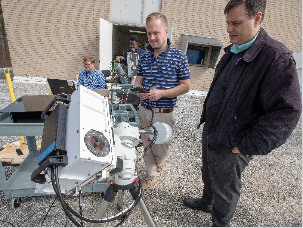
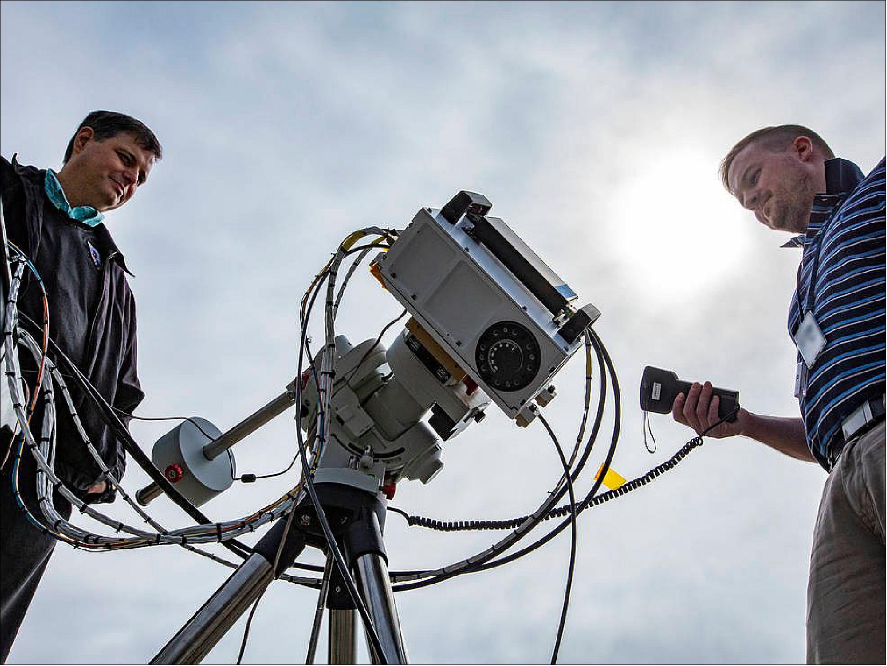
A prototype of an instrument that could one day extend NASA's data record on the recovery of Earth's ozone layer recently got its first glimpse of the Sun. A team at NASA's Langley Research Center in Hampton, Virginia, took the Stratospheric Aerosol and Gas Experiment (SAGE) IV Pathfinder onto the roof of one of the center's buildings to conduct Sun-look tests. 1)
These tests are critical for an instrument that makes measurements of ozone and tiny atmospheric particles called aerosols by looking at the light from the rising or setting Sun as it passes through Earth's atmosphere — a technique called solar occultation. Prior to being brought outside, SAGE IV Pathfinder had undergone months of testing in a lab.
"There's nothing like getting out and taking a look at the Sun, which is extremely bright in comparison to anything we can produce in the laboratory," said Charles Hill, co-principal investigator for SAGE IV Pathfinder.
A full-blown SAGE-IV mission would be a significant new chapter in the SAGE story, which began in the late 1970s and continued through the following decades. The data collected on SAGE-I and the following instrument SAGE-II, were critical to the discovery of the Earth's ozone hole and the creation of the 1987 Montreal Protocol, an international treaty that banned the use of chlorofluorocarbons (CFCs). CFCs were used as refrigerants and in aerosol spray cans and are significant contributors to stratospheric ozone depletion.
Unlike ozone in the troposphere, the lowest part of the atmosphere, which has negative effects on the air we breathe, ozone in the stratosphere, the layer of the atmosphere that begins around 6 miles (10 km) above the surface, is vital for life on Earth. By absorbing most of the Sun's harmful UV rays, stratospheric ozone acts as Earth’s sunscreen and helps protect people from skin cancer, cataracts, and immune system suppression, and prevents crops from being damaged.
SAGE-III, which launched to the International Space Station in 2017, is monitoring the recovery of the ozone layer, effects on the stratosphere from events such as volcanic eruptions and extreme wildfires, and stratospheric nitrogen dioxide and water vapor.
SAGE-IV is in a prototype state and unlike its washing-machine-sized predecessors would fit neatly within the confines of a CubeSat that's not much bigger than your average shoebox. That reduction in size, which comes from an improved measurement technique that images the entire Sun rather than looking at only a small portion of it, would make it more cost effective.
“For this type of measurement, keeping the data record continuous and validating new instruments against what’s already there is critically important,” said Rob Damadeo, the other co-principal investigator. "There may be overlap with existing instruments, and it’ll last long enough that you then put up the next one so that they have some overlap. That way when the old one drops off, the new one takes over and you keep stepping along like that.”
The team envisions a scenario where a small constellation of SAGE-IV CubeSats would eventually orbit Earth. This would simultaneously expand the measurements to more of the globe and reduce the time between observations of any location from a month down to a week.
That future is still aspirational for now, though. The SAGE-IV team is working hard to finalize designs for a spaceflight instrument, and exploring opportunities to move beyond prototype status to continue these important measurements.
The Sun-look tests took place in early March, just as concerns about COVID-19 began forcing widescale closures around the U.S. Those circumstances required the team to end testing a few weeks before they were ready to stop, but they're looking forward to completing testing, analyzing the data and hopefully moving the project into its next phase.
"We're planning for it," said Mike Obland, SAGE IV project manager. "We're actively planning for a return and how to optimize our time and finish our critical testing safely when we get back."
SAGE-IV Pathfinder involves partnerships with the private sector and is funded by the Instrument Incubator Program in the Earth Science Technology Office, which is part of the Earth Science Division in NASA’s Science Mission Directorate. Additional funding comes from Langley's Science Directorate. Funding for some of the instrument's telescope technology is being advanced through NASA's Small Business Innovation Research program.
Instrument Design
The SAGE-IV concept originated with a desire to enable sustainability in future ozone and aerosol continuity measurements and, if possible, improve the overall data quality. Such a capability is achievable by continuing to use the observation method of solar occultation (i.e., observing the Sun as it rises or sets through the atmosphere) but with a change to 2D spatial imaging from the previous scanning technique. When it comes to solar occultation measurements, pointing knowledge is critical and a great deal of effort is expended to ensure the best possible measurement with the current SAGE scanning architecture. With solar imaging, pointing knowledge on the solar disk is intrinsic, essentially replacing multiple assumptions about pointing with measurements to enable an improved data product. Imaging allows for better characterization of the light source (i.e., the Sun) and introduces the possibility of new data products. It has the added benefit of removing massive and/or expensive tracking mechanisms to shrink the overall instrument size. 2)
While switching to solar imaging offers many improvements, it also requires a complete reconsideration of instrument requirements instead of just copying them directly from older instruments. With a history of successful SAGE missions that have demonstrated the ability to use solar occultation to measure stratospheric aerosol and trace gases and a desire to, at a minimum, provide results with the same data quality, it is logical to inherit the science requirements from previous SAGE instruments for use with SAGE-IV. At the highest level, these requirements translate into the ability to measure the different species of interest in the stratosphere at the desired precision and vertical resolution as shown in Table 1. While vertical resolution can be fairly uniform for a solar occultation instrument, precision varies with altitude and the precisions listed in Table 1 are the best theoretically possible that should be attainable within the stratosphere with this instrument.
Species | Altitude range | Best precision | Vertical resolution |
Ozone | 0*-70 km | 1% | 1 km |
Aerosol extinction | 0*-40 km | 5% | 1 km |
Water vapor | 0*-60 km | 10% | 2 km |
Nitrogen Dioxide | 10*-50 km | 5% | 1 km |
*Stated altitude or cloud-top, whichever is higher | |||
These high-level science requirements were translated into performance requirements and SAGE-IV was designed to meet each requirement. Characteristics of SAGE-IV are shown in Table 2. While not a science requirement, the overall form factor of the instrument was considered as part of the design process. During preliminary design work, it was determined that key decisions reduced the size of a potential SAGE-IV instrument drastically compared to previous SAGE instruments and that it could potentially fit within a 6U CubeSat (30 x 20 x 10 cm) for a future flight mission. If possible, such a design decision would offer significant savings in the cost of mission architecture and accelerate any follow-on work for a science mission. This choice would further support the concept of offering ”sustainable" continuity science; therefore, the decision to use a 6U CubeSat to introduce size constraints on the instrument was made.
Characteristic | Specification |
Mass (CBE + 30% cont.) | 6.4 kg |
Power (CBE + 30% cont.) | 46.4 W |
Volume (instrument + bus) | 10 cm x 20 cm x 30 cm (6U CubeSat) |
Pointing accuracy requirement | ±3 arcminutes |
FOV (Field of View) | 1º |
Aperture size | 6.2 cm |
Angular resolution | 0.5 arcminutes |
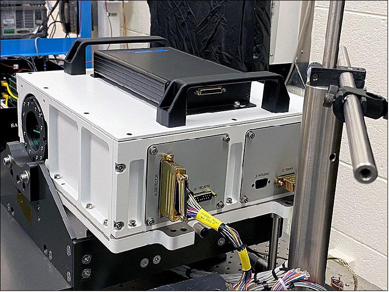
Throughout the instrument integration and test period, a surrogate chassis (Figure 3) was used to house the telescope, filter wheel assembly, and detector assembly. The chassis is slightly larger than a 6U CubeSat bus to allow for working room and has feedthrough connections to all of the electronics that are housed externally, allowing the system to be largely sealed to outside dust and debris. There are also gas inlet and outlet ports that are connected to a nitrogen purge system. The gas system maintains a slight positive pressure of ~100% N2 in order to allow the detector to be cooled to temperatures below the ambient dew point. Descriptions of the individual subsytems are included below.
Detector
For SAGE IV, the availability of detectors was a limiting factor. The large Signal-to-Noise Ratio (SNR) requirement is in a shot-noise-limited regime (i.e., where the noise follows Poisson statistics and is equivalent to the square root of the signal) and so to achieve a SNR of ~2000, a pixel on the detector would need a minimum well-depth of 4 million electrons over the range of linearity. However, to give margin on the linearity requirement and avoid saturating the detector, a requirement of a minimum pixel well-depth of 5 million electrons was used. Given a desired spectral range in the UV/VIS/NIR, the use of silicon as the photosensitive substrate is the most logical choice and has the added benefit of a relatively low dark current (compared to the signal) at ambient temperatures. This requires simple temperature control for stability during the few minutes encompassed by an occultation, instead of cryocooling, and is easily achievable with the use of a Thermoelectric Cooler (TEC).
The sensitivity of the measurement and the fact that SAGE-IV images require that each pixel on the detector be individually read out, instead of the "bucket brigade" style on a traditional Charge-Coupled Device (CCD); therefore, an additional requirement was that the detector be a PIN diode array with a readout capability similar to those in Complementary Metal Oxide Semiconductor (CMOS) devices. Lastly, a more simple requirement was that the detector needed to be a two-dimensional array of square pixels with at least 120 by 120 pixels in each dimension (from FOV requirements). The combination of these requirements on the detector left few commercially available options. The CHROMA 640, a hybrid, visible-infrared Focal Plane Array (FPA) imager from Teledyne Imaging Sensors (TIS) was competitively selected as the detector for the IIP (Instrument Incubator Program), and the flight detector will be selected through a competitive Government procurement process from vendors whose products meet the requirements.
The CHROMA 640 FPA image capture sequence is initiated through the use of an external control module known as Focal Plane Electronics (FPE). The FPE interfaces to the FPA to capture data and provides captured images via a CameraLink interface to user hardware. The CameraLink interface provides the data interface for receiving images as well as a serial interface for controlling the FPE and FPA settings via register reads and writes. The FPE supplies the necessary analog and digital bias voltages to the FPA, performs the analog-to-digital converter (ADC) conversion of the Readout Integrated Circuit (ROIC) outputs, and provides the system clock. The FPE system clock can be configured to operate at a 10 megahertz (MHz), 1 MHz, or 100 kilohertz (kHz). All timing and auxiliary power is generated internal to the ROIC further simplifying the image capture sequence.
The ROIC generates the frame and data valid signals, synchronized with the input system clock, to be used by the FPE to read the ROIC analog outputs and capture the detector image. The start of the integration and read state machines in the ROIC is controlled by an external Frame Synchronization (FSYNC) signal or via serial command. SAGE-IV firmware triggers the FSYNC signal based on the filter wheel position such that images are captured when each filter in the wheel is aligned with the instrument optical path. The baseline configuration captures a single image at each filter position as the filter wheel turns at 30 revolutions per minute (RPM).
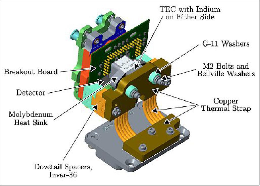
The SAGE-IV ground demonstration unit's detector requires both cooling below the ambient environment and stability to achieve its science goals. The relevant thermal requirements and environments for the detector are captured in Table 3. A TEC was determined to be the best option to provide cooling to the detector based on the requirements. LairdTMmodel CP10-31-05 was selected for the design primarily because it had a short lead time, a geometry that meets requirements, and 10 units could be ordered easily. The geometry and volume constraints of the instrument assembly necessitate a flexible thermal strap to transfer the waste heat from the TEC to the surrogate chassis.
A molybdenum heat sink was bonded to the detector using Scotch Weld 2216 epoxy. Molybdenum was chosen because its coefficient of thermal expansion (CTE) is very close to the CTE of the ceramic (alumina) detector case, and it has an acceptably high thermal conductivity for this application. The matched CTE reduces deformation and stress on the detector when cooled. The 2216 epoxy was chosen for its relatively good adhesion to gold; the heat transfer pad on the detector was gold coated to allow soldering if needed. A lap shear test was conducted at Goddard Space Flight Center (GSFC) to compare 2216 lap shear strength when bonded to gold or bare aluminum. Shear strength results for gold were about half of what they were for bare aluminum, however the total strength was deemed sufficient for this application. The molybdenum block serves as the mechanical and thermal connection to the TEC and heat sink strap. Control of the TEC is described in the Avionics section.
Requirement | Value |
Detector temperature | 10ºC |
Detector temperature stability | 0.1ºC |
Detector heat dissipation | 0.2W to 0.3W |
Detector focus tolerance | ±8 µm |
Detector X&Y tilt tolerance | <0.039º (0.68 mrad) |
Detector CTE (Coefficient of Thermal Expansion) | 6 µm/(mK) |
Expected ambient temperature range | 10ºC to 30ºC |
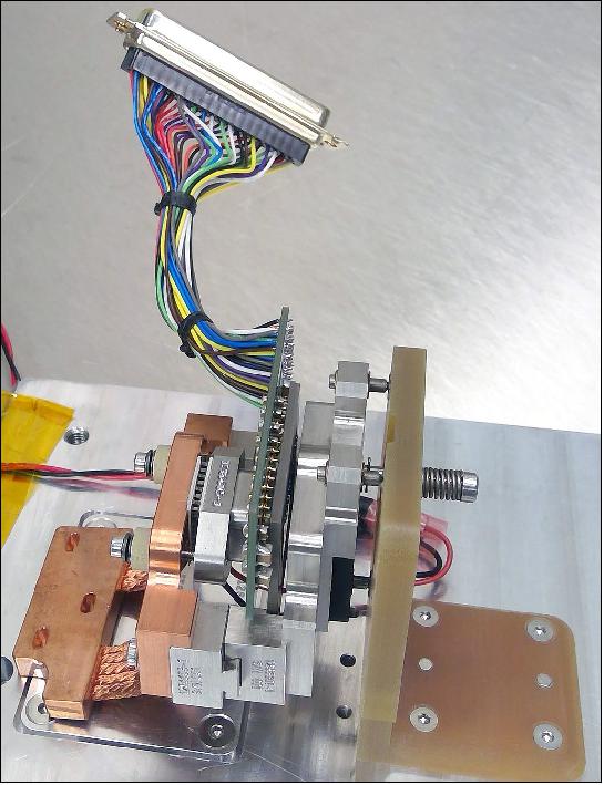
A drawing of the final detector thermal control design is shown in Figure 4 and a picture of the as-built detector assembly is shown in Figure 5.
Optical Layout
As with most instruments, the telescope design must be tailored for its specific use. The solar disk is ~32 arcminutes across and the science FOV encompasses ~40 arcminutes. To add margin for pointing uncertainty for a future on-orbit mission, the total FOV was required to be 1º across. With the detector already chosen, the telescope needed to ensure that 0.5 arcminutes corresponded to 30 µm at the focal plane (i.e., the pitch of a single pixel on the detector). Also, in order to make use of spectral filters, the telescope had to afford a location where collimated light could be passed through the filters.
Beyond these requirements, care was taken during the design process of the telescope to ensure the best possible performance. Solar occultation measurements routinely span 4-5 orders of magnitude and switching from scanning to imaging meant that range would be contained in a single snapshot. The dynamic range in the observations means that mitigating stray light (i.e., image ghosting, out-of-field stray light, and in-field stray light) is of paramount importance. Furthermore, the telescope needed to maintain these performance requirements through the thermal environment that could be encountered on-orbit. Lastly, like previous SAGE instruments, the optical train would require an attenuator to block out the majority of light from the Sun to prevent saturating the detector, but this is performed as the last step to optimize the throughtput of the system.
Key requirements that drove the optical design of the multispectral imager include: (1) image quality, measured as encircled energy at the focal plane; (2) out-of-field stray light rejection; (3) suppression of ghost images from Fresnel reflections; and (4) ease of integration of a filterwheel with narrow-band filters to perform multispectral measurements. As image quality and encircled energy are a function of in-field stray light, only unobscured systems were considered with the largest reasonable aperture. It is expected that there will be meaningful temporal and spatial thermal gradients during operation caused by periodic solar flux and the small size of the host spacecraft. The selection of materials for each of the primary component types (metering structure, mounts, and optics) is critical to maintaining alignment through the range of operating conditions, as well as ensuring the structural survivability during launch. Exhaustive materials trade studies were performed to understand which metering structure material would perform best, and ultimately a carbon fiber metering structure, with Invar-36 mounts and Zerodur® mirrors were selected.
The amount of stray light incident on the FPA because of in-field or out-of-field scattering and ghost reflections was quantified to verify that it would not be strong enough to corrupt the science image. Measurements obtained at the Space Dynamics Laboratory (SDL) stray light testing facility went extremely well, with good comparison to conservative simulations and modeling. The solar rejection filter (SRF) ghost showed up where expected and agreed with the model, with minor variations in magnitude. Because of the success of the measurements and their agreement with simulation, the model has been validated, thus eliminating the need for expensive testing as long as good qualification of components is achieved. Encircled energy was measured to be between 92.4% and 94.2% over the image plane, which exceeded requirements and was within the predicted as-built performance range, including manufacturing tolerances.
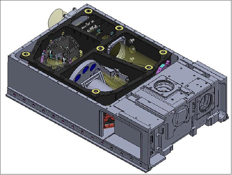
A model of the SAGE-IV satellite within a 6U bus is shown in Figure 6. The metering structure is shown in black, and the optical path can be traced from the aperture in the top right corner through the filter wheel (filters shown in blue) and ending on the detector in the top left corner of the bus. The lower 2U of volume is reserved for spacecraft bus avionics.
Filter Wheel Assembly (FWA)
The imaging technique necessitated the use of spectral interference filters. A similar approach was used by the highly successful SAGE-II instrument during its 21 years of operation. For SAGE-IV, the decision was made to incorporate a filter wheel into the design. The wheel itself would need to fit within a CubeSat framework (i.e., <10 cm with margin), but would ideally be as large as possible to incorporate as many filter locations as possible to maximize science value. To achieve science and onboard characterization goals (e.g., dark current and flat-fielding), the filter wheel would need at least 9 locations. With a sampling frequency requirement of one image at each wavelength of interest every two seconds, the wheel would need to spin at 0.5 Hz. The size of each filter is a coupled requirement with the telescope design and detector timing to allow for adequate integration time through the clear aperture of each filter as the filter wheel rotates without obscuring the light or introducing vignetting. Lastly, to ensure detector integration is appropriately timed, the rotational location of the filter wheel would need to be known to within the timing limits of the ability to readout the detector.
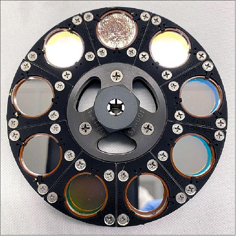
The SAGE-IV FWA is designed to house eight transmissive bandpass filters and filter/diffuser combinations along with one opaque flat mirror as required to perform the SAGE-IV science. The FWA is designed to permit filters and diffusers to be changed throughout the IIP project, allowing filters from different vendors and filter/diffuser combinations to be tested. The filter wheel size is limited by the instrument chassis size and is restricted by the placement of the telescope and detector. The FWA mounts to the motor assembly, which nominally turns the filter wheel at 30 rpm and measures angular position with an encoder. The FWA is designed to place each of the nine elements into the optical path as the filter wheel turns. The filter wheel and motor are supported by the motor mount, which holds the full assembly at a 7.5º angle from the chief ray to direct Fresnel reflections into the beam dump. The assembled filter wheel is shown in Figure 7.
Each of the nine elements in the filter wheel serves the purpose either as a science channel specifically chosen to observe a target species or as a characterization channel chosen to enable characterization of the instrument's performance during routine operations (e.g., as we would expect on-orbit for a future flight mission). For the purpose of the IIP, more combinations of filters and diffusers than can simultaneously fit in the wheel were procured to facilitate testing of different combinations. To enable measurements of detector dark current during science observations, one spot within the wheel has a counter-bore with a flat mirror inserted. The counter-bore ensures that no light passes through and the mirror is representative of the interference filters that reflect the majority of the light back into the telescope beam dump. With a \light block" as an element in the filter wheel, a dark current image can be taken as part of the standard 0.5 Hz data collection and potential thermal transient effects can be observed, characterized, and removed during science data processing. The spectral locations of the bandpass filters used for the IIP are essentially copied from those used for the SAGE-II mission, but are not completely representative of those that would be used for a future flight mission. Instead, they were chosen based on their utility in characterizing instrument performance in the lab and during final Sunlook testing, and are detailed in Table 4.
Center wavelength | Bandwidth | Purpose |
386 nm | 15 nm | Aerosols / Blue-end response |
448 nm | 2 nm | Nitrogen dioxide |
452 nm | 2 nm | Nitrogen dioxide |
525 nm | 15 nm | Aerosols |
600 nm | 15 nm | Ozone |
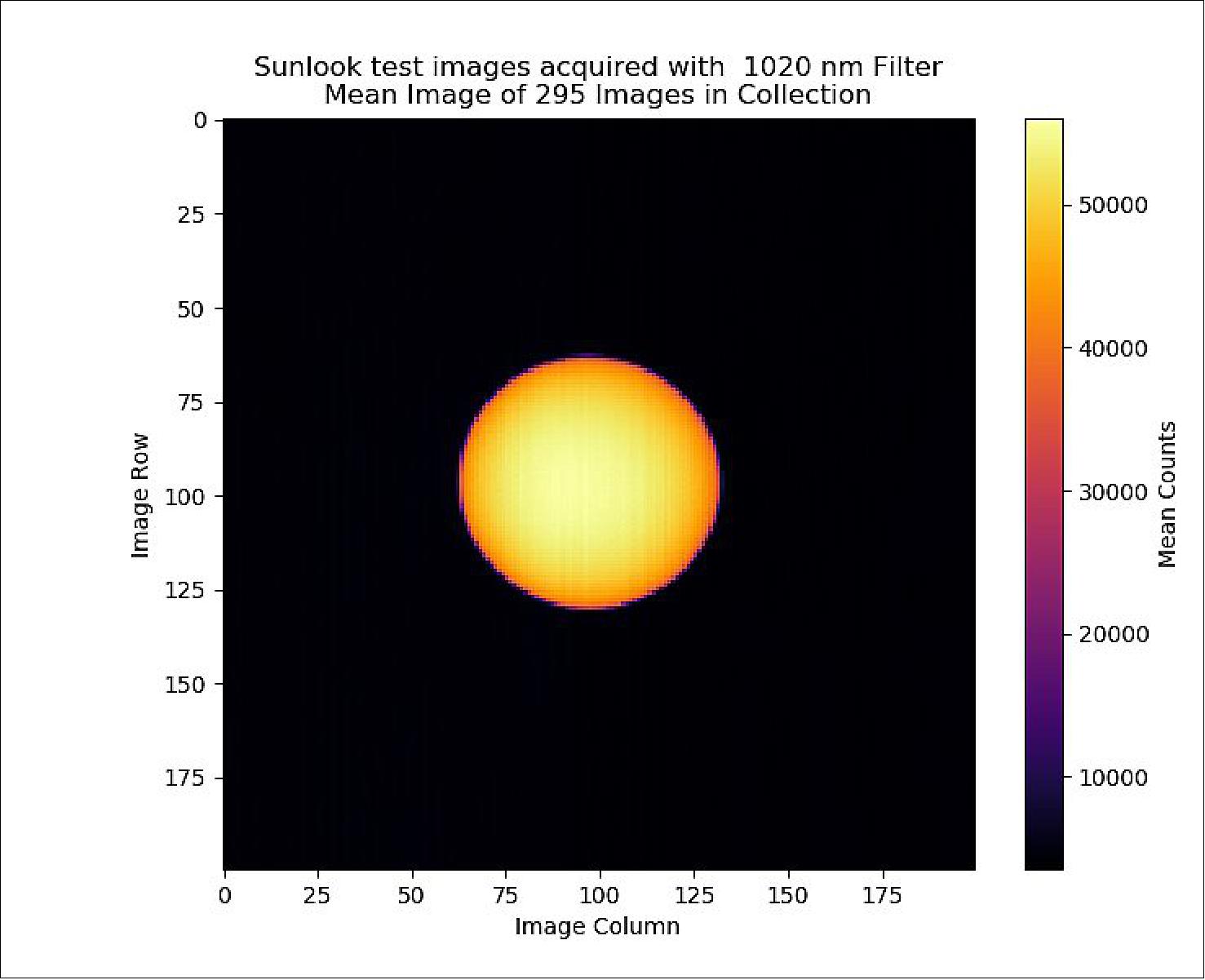
1020 nm | 15 nm | Aerosols / Red-end response |
In addition to the ”light block", diffusers are the other characterization element within the filter wheel. Any time two (or more) pixels on a detector look at different spatial scenes and need to be compared, a pixel-to-pixel cross-calibration or flat-fielding" correction will need to be applied to the data to account for spatial non-uniformities in pixel responsivity. This is a standard step in image processing that is often not required for simple pushbroom spectrometers. While flat-fielding is easily characterized in the lab, this behavior will change in orbit from radiation damage and may also be susceptible to minor changes with temperature.
As such, it is necessary to perform this kind of instrument characterization in space. For a highly sensitive measurement such as solar occultation, observing the solar disk through a diffuser can provide a sufficiently uniform source to perform pixel-to-pixel cross-calibrations. Incorporating such a characterization measurement into the filter wheel has the added bonus of observing how pixel response differs with changes in the thermal profile of the spacecraft through extended exoatmospheric measurements. Such thermal transients have been shown to be potentially problematic and difficult to characterize for previous SAGE instruments. Several engineered diffusers of 1, 2, 5, and 10 degree divergence angles were procured for testing as part of NASA's IIP (Instrument Incubator Program).
A trade study to investigate motor options was performed early in the SAGE IV IIP project. A specification for the desired motor was developed from the inertia of the filter wheel, the desired 30 rpm rotational speed, environmental characteristics, and the motor needing a path to flight on a Low Earth Orbit (LEO) CubeSat. Because the filter wheel inertia was low, a direct drive solution was desired. A Phytron motor was selected and purchased for the IIP demonstration with a path to flight solution. The Phytron motor purchased for SAGE-IV is vacuum compatible and included a resolver. The Phytron stepper motor and resolver met all motor requirements and fit in the available volume allocated in the instrument chassis.
Avionics
The SAGE-IV IIP (Instrument Incubator Program) avionics design is implemented in 3 subsystems (Camera Controller, Motor Controller, and Instrument Controller) using COTS (Commercial Off-the-Shelf) development boards to keep avionics costs low for the IIP effort while providing a path to flight. The selection of the instrument controller and motor controller development boards provides a path to flight utilizing a Microsemi RTG4 for the flight design and maximizes the re-use of software and firmware developed or acquired for the IIP. The instrument and motor controller firmware were combined into a single design for demonstration and a digitizer board developed by NASA/GSFC was integrated into the instrument controller to replace the camera controller electronics and detector Focal Plane Electronics (FPE), integrating all SAGE-IV subsystems into a single design for demonstration in preparation for flight.
Additional peripherals needed to complete the instrument IIP avionics were developed in-house at NASA/LaRC. These developments include an electronic board stack for the instrument controller providing digital interfaces (RS-232, RS-422, DIO) for communications with other subsystems, housekeeping voltage and temperature monitors, and a TEC controller for governing the detector temperature.
The camera controller avionics consists of a Xilinx ZC702 Evaluation Board with a Sundance Digital Signal Processor (DSP) board to interface with the Teledyne detector via a CameraLink interface. The ZC702 System on a Chip (SoC) provides programmable logic combined with two ARM® CortexTM-A9 MPCoreTM processors with common peripherals. Only one of the ARM processors is used. The embedded software handles the overall camera controller processes, while the programmable logic supports the higher speed state machines needed to implement high speed interfaces such as the CameraLink and Ethernet interfaces. The CameraLink interface is used for capturing detector images from the Teledyne FPE as well as providing a command and telemetry interface to the FPE via the embedded serial interface.
A MicroSemi SmartFusion2 Dual-Axis Motor Control Kit is used as the stepper motor controller for turning the filter wheel. The SmartFusion2 SoC provides programmable logic combined with an ARM® CortexTM-M3 processor with common peripherals. The embedded software handles the overall motor controller processes, while the programmable logic supports the higher speed state machines and controllers needed to implement the stepper motor controller. The motor controller provides for stepper motor control and encoder feedback for monitoring the filter wheel position. Custom firmware was developed to signal the instrument controller at specified encoder positions providing an indication when the filter wheel is in position to capture an image. This signal is used by the instrument controller (combined with the arm signal from the camera controller) to generate the signals to capture an image.
The main instrument controller is developed using a MicroSemi SmartFusion2 Advanced Development Kit. The SmartFusion2 SoC is of the same family as the one used for the motor controller providing programmable logic combined with an ARM® CortexTM-M3 processor with common peripherals. The embedded software handles the overall instrument control. The programmable logic implements custom firmware needed to control the other subsystems. The firmware interfaces with custom electronics boards required for communications with other subsystems, housekeeping measurements, and a TEC controller. The TEC controller interfaces to a TEC for cooling or heating the detector. The SmartFusion2 was chosen for the IIP since it has a path to flight using the MicroSemi RTG4.
The SmartFusion2 Advanced Development Board interfaces to other subsystems via a set of custom electronics. The stack electronics provided for expansion where the SAGE-IV TEC controller was added to the top of the stack and integrated into the instrument controller. The TEC controller provides closed loop temperature control for the detector. The TEC mounts to the molybdenum mounted to the rear of the detector. The TEC controller provides Pulse Width Modulation (PWM) control of the TEC power. A Resistance Temperature Detector (RTD) bonded to the molybdenum block is used as the sensor for closed loop control. The Proportional-Integral (PI) controller is implemented in the SmartFusion2 programmable logic interfacing through the instrument stack to the TEC board and is controlled by the embedded software. The embedded software provides the capability to set controller gains, temperature setpoints, modes of operation, and select one of the two RTD sensors inputs (TEC board RTD or Housekeeping board RTD). The embedded software also collects health and status data including onboard voltages for TEC controller operation.
The instrument controller, motor controller, and camera controller are integrated into an avionics chassis for the IIP. The integrated avionics is designed to be portable in order to support both the laboratory testing and the outdoor Sunlook test.
Firmware & Software
Firmware development for the SAGE-IV IIP instrument is focused on the Instrument Controller Board (ICB) FPGA. The ICB FPGA contains most of the interfaces and control systems for the instrument. The Motor Control Board (MCB) FPGA contains only a Universal Asynchronous Receiver-Transmitter (UART) interface to the ICB, a Microsemi IP core for stepper motor control, and custom firmware for monitoring the encoder position to signal when the motor reaches one of 9 specified positions. Likewise, the Camera Controller Board (CCB) FPGA contains a UART interface to the ICB, IP cores for Ethernet and CameraLink interfaces, and custom control firmware for controlling the capture of detector images.
The primary goal of the SAGE-IV IIP software development effort was to allow for a successful ground demonstration of the instrument while allowing for a path-to-flight for many of the developed embedded software components. It is important to note that it was deemed out-of-scope to develop flightlike mission operations GSS (Ground Support Software) for the IIP. Therefore, the majority of the effort for developing path-to-flight software components was focused on the embedded software rather than the GSS. This, however, does not preclude the team from utilizing the GSS components for future lab testing and development for a flight project.
The design of the SAGE-IV IIP embedded software is spread across three boards (ICB, MCB, and IPB (Image Processing Board). These boards communicate via serial UART interfaces, utilizing the same interface software for simplicity and modularity. This design choice was made by the hardware, firmware, and software teams because it provided the quickest route to a functioning instrument while still allowing for the development of path-to-flight software. With minimal additional effort, the software was able to be written such that each module ports easily to a single board once the hardware and firmware components are developed.
The ICB software controls the SAGE-IV IIP instrument. The MCB software handles the command and control of the stepper motor. The IPB software handles the image data processing for the instrument. FreeRTOS was chosen as the operating system for the embedded software components for several reasons. Foremost, FreeRTOS is a lightweight, open source, and widely used RTOS (Real-Time Operating System). Additionally, the tooling, documentation, and resources for FreeRTOS are ample and allow for quick development of the necessary embedded software components. Lastly, FreeRTOS has flight heritage 3) and is intended to be the operating system of choice for a future flight project. This selection, however, does not preclude the team from changing operating systems if desired, as a porting effort between RTOSs would be feasible due to large consistencies between RTOS APIs (Application Programming Interfaces).
For the SAGE-IV IIP, basic operations of the instrument require ground support software that, at a minimum, provides a means to visualize instrument telemetry and construct instrument commands. The software team chose to utilize the popular and open source application COSMOS available from Ball Aerospace to fulfill these needs. In addition to these basic features, COSMOS offers, the ability to graph, log, develop scripts, automate tests, create documentation, and build custom displays. Utilizing this software sped up the software team's development effort significantly and offered the team with various tools out-of-the-box that would not have otherwise been available.
In addition to basic commanding and telemetry, operation of the instrument requires real-time display and logging of the science image data. For this, utilizing COSMOS was not possible because COSMOS does not natively support displaying images. To meet this requirement, the software team chose to build a lightweight custom image processor utilizing Python. The application logs the images and associated metadata in .raw and .png format for science post-processing and visualization purposes respectively.
Satellite Bus
Blue Canyon Technologies (BCT) was competitively selected as a partner for the IIP instrument and the SAGE-IV baseline bus design is the BCT XB6 6U CubeSat bus. The bus for the flight instrument will be competitively selected through a Government procurement process and must meet the SAGE-IV mission requirements for power, available instrument volume (the SAGE-IV instrument requires approximately 4U) and pointing accuracy (3 arcminutes).
Launch Vehicles
As a 6U CubeSat, there are expected to be numerous rideshare opportunities (e.g., SpaceX, NASA CubeSat Launch Initiative) or even low-cost dedicated launch opportunities (e.g., Rocket Lab) when SAGE-IV is ready to launch, so no specific launch vehicle has been designated. The ideal orbit for a SAGE IV demonstration mission would be an ”ISS-like" orbit (mid-inclination, 500 km altitude) that allows for maximum overlap with the SAGE-III/ISS orbit, and therefore, maximum number of validation opportunities. However, other orbit inclinations would be acceptable assuming the orbital lifetime allows for an acceptable number of comparison opportunities with SAGE-III/ISS.
Preliminary Test Results
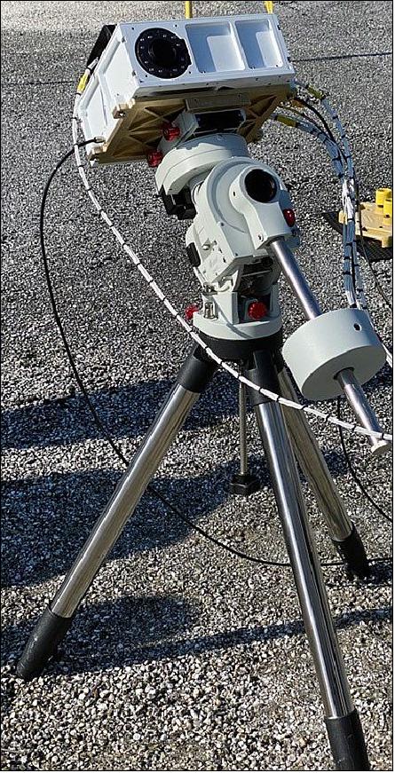
After the instrument was fully integrated, system checkout and characterization testing occurred in the laboratory. In order to evaluate operational performance in a relevant environment, the SAGE-IV IIP instrument was positioned outdoors on an equatorial mount as shown in Figure 8. The motorized equatorial mount provides seemless tracking and positioning with respect to the Earth's axis of rotation. Closed loop control of the system from the SAGE-IV operational software automatically maintained the Sun in the instrument FOV. Once aligned, the instrument was able to track the Sun by rotating along a single axis, allowing for the straight-forward collection of images of the Sun. Tests were performed on cloudfree, sunny days at elevated heights to reduce the effects from obstructions.
While the primary purpose of the Sunlook test was to demonstrate the instrument's ability to capture images in full view of the Sun, it also presented an opportunity to assess the integrated system performance (i.e., optical system, electronic hardware, and the underlying software) in dynamic conditions outside of the laboratory. It also enabled analysis of images with a solar target as opposed to the calibrated light source used in the lab. The resultant images are then compared to those captured in a laboratory setting to further examine any deviations in SNR values. Further analysis was performed to ensure that the target image was distortion free. Ideally, the target image should be absent of any distortions from the apparent mechanical vibrations of optical components or external vibrations to the system.
Each test image was attempted to be captured at 80% well capacity or approximately 52000 DN. The images are captured during continuous revolution of the rotating optics of the filter wheel (known as Science mode operation), thus the integration time must be adjusted to maintain SNR across each frame. When active tracking was not on, the Sun moves in the instrument's field of view as the Earth rotates. To account for this motion, a centroiding routine was developed to find the center of the image within the field of view. Once the centroid is determined, this point is then aligned with each successive frame and averaged. An example of this centroid averaging is shown in Figure 9. Proper centroiding enables corrective pixel averaging of the Sun in temporal space.
Sunlook testing was interrupted by COVID-19 restrictions. The data set that was able to be obtained is being analyzed and further testing will continue when possible.
Summary
The SAGE-IV (Stratospheric Aerosol and Gas Experiment-IV) is a solar occultation imager concept capable of measuring ozone, aerosol, and other trace gas species with the same quality as previous SAGE instruments (including SAGE-III currently on the ISS). A ground-demonstration unit has been built and tested, meeting technical requirements that verify the ability of SAGE IV to meet measurement requirements for many important science objectives once in orbit. SAGE-IV takes advantage of current technologies and a novel solar occultation imaging architecture to reduce its overall size to fit within a 6U CubeSat bus. SAGE-IV provides a sustainable solution for monitoring these key constituents of the atmosphere for the decades needed to verify ozone layer recovery to 1980s levels and beyond, maintaining vitally important atmospheric data records during that time.
References
1) Joe Atkinson, ”Prototype Ozone Monitoring Instrument Undergoes Sun-Look Testing,” NASA Feature, 23 July 2020, URL : https://www.nasa.gov/feature/langley
/prototype-ozone-monitoring-instrument-undergoes-sun-look-testing
2) Michael Obland, Charles Hill, Robert Damadeo, John Leckey, ”Sustainable Ozone and Aerosol Measurements from a 6U CubeSat: The Stratospheric Aerosol and Gas Experiment (SAGE) IV Pathfinder,” Proceedings of the 34rd Annual AIAA/USU Virtual Conference on Small Satellites, August 1-6, 2020, Logan, UT, USA, paper: SSC20-III-05, URL: https://digitalcommons.usu.edu
/cgi/viewcontent.cgi?article=4722&context=smallsat
3) Larry Kepko, Chuck Clagett, Luis Santos, Behnam Azimi, Daniel Berry, Todd Bonalsky, Dean Chai, Matthew Colvin, Alan Cudmore, Allison Evans, Scott Hesh, Sarah Jones, James Marshall, Nicholas Paschalidis,Zach Peterson, Juan Rodriquez, Marcello Rodriquez, Salman Sheikh, Scott Starin, Eftyhia Zesta, ”Dellingr: NASA Goddard Spaceflight Center's First 6U spacecraft”Proceedings of the 31st Annual AIAA/USU Conference on Small Satellites, Logan UT, USA, Aug. 5-10, 2017, paper: SSC17-III-06, URL: https://digitalcommons.usu.edu/cgi/viewcontent.cgi?article=3614&context=smallsat
The information compiled and edited in this article was provided by Herbert J. Kramer from his documentation of: ”Observation of the Earth and Its Environment: Survey of Missions and Sensors” (Springer Verlag) as well as many other sources after the publication of the 4th edition in 2002. - Comments and corrections to this article are always welcome for further updates (eoportal@symbios.space).