Reentry Test Simulations
Technology Development
Reentry Test Simulations (Demising a SADM, in Theory and Practice)
Drive to destruction References
ESA and many other countries worldwide require that satellites remove themselves from LEO orbits within 25 years of mission completion to avoid the creation of ever more space debris in the future, and to keep the Low Earth Orbit (LEO) region as clear as possible for active missions. In practice, this often means re-entering into the Earth’s atmosphere.
When a spacecraft reenters from space in the Earth’s atmosphere, operators are required to minimize the risk of causing casualties. In particular, to perform a so-called uncontrolled reentry, an operator has to prove that the on-ground casualty risk posed by its satellite is lower than 1 in 10 000. 1)
Therefore, a thorough analysis is performed to assess how the spacecraft will fragment and ablate during reentry in order to estimate the size and number of fragments that could reach the ground. In recent years, multi-disciplinary assessments identified the critical equipment in terms of demisability. Various factors, such as the materials used and shielding of the spacecraft, contribute to this criticality. For example SADM (Solar Array Driving Mechanisms) were identified as critical because they contained critical materials such as steel and titanium.
This is why in 2020, Kongsberg Defence & Aerospace (KDA) started an investigation supported by ESA, Hyperschall Technologie Göttingen GmbH (HTG) and the German Aerospace Center (DLR), to develop a detailed model of a SADM on one of the reentry simulation software tools, to assess its demisability depending on the altitude where the unit is separated from the spacecraft. They also planned to propose changes to the SADM design that could enhance its demisability. Then, an on-ground test campaign was conducted to validate the models.
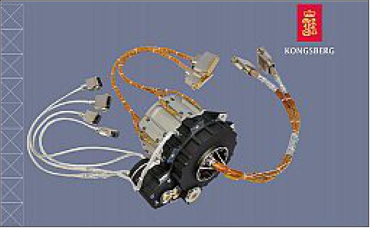
The unit that they chose to investigate is the KARMA-4 TG (Kongsberg Adaptive Rotational Mechanism Assembly), a fully qualified Kongsberg Third Generation SADM, envisaged for LEO and GEO usage.
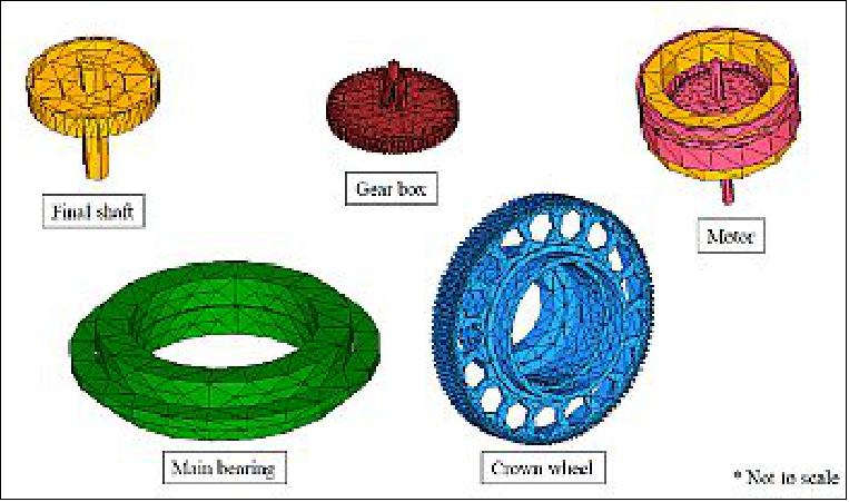
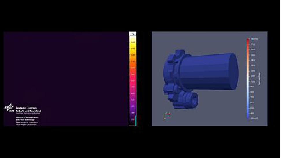
The modelling of the SADM was first done in SCARAB by HTG. A SADM is made up of many sub-components which had to be modelled separately, as shown in Figure 2. Analyzing the demise phenomenology of the SADM in the simulations allowed to identify each step that needed to be confirmed during the testing phase (e.g. subsequent melting or separation of two sub-components).
The detailed baseline model for KARMA-4 TG is simulated to be demisable with a 5% significance level at 76 km release altitude. Moreover, some iterations were performed to increase confidence in this result, such as exploiting different reference trajectories or assessing the impact of modelling simplifications on the main bearing. Such simplifications were seen to improve slightly the most probable demise altitude. Another interesting investigation was to use the ESTIMATE material database instead of the SCARAB database, because it resulted in a demise altitude of 80 km with 5% significance level.
To enhance the SADM demise, KDA proposed to change the material of the screws to one with a lower melting temperature (e.g. aluminium). This would allow for an earlier fragmentation of the SADM into its sub-components. The benefit of such a design was simulated by triggering this fragmentation event at a lower temperature. This lowered the minimum release altitude to 70 km.
Test Predictions
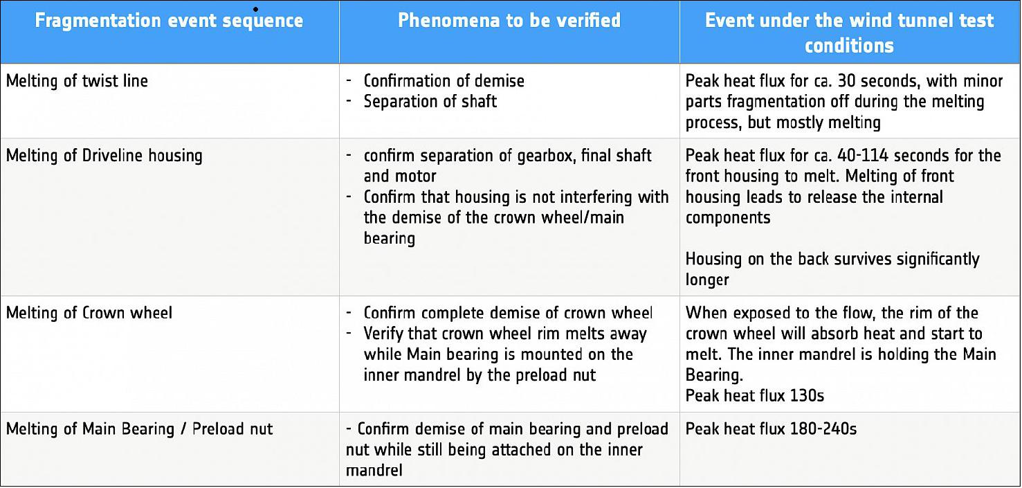
According to DIVE, the ESA Guidelines for Analyzing and Testing the Demise of Man Made Space Objects During Re-entry, it is necessary to produce predictions for the demise phenomenology prior to the test. To do so, the SCARAB model was modified, in accordance with the test sample, to be able to first predict and later recreate the test. Using the heat flux steps provided by DLR, HTG was able to simulate the test performed in the PWT (Plasma Wind Tunnel).
This allowed them to produce an expected sequence of events and to determine the PWT test conditions that should allow to observe the demise phenomenon that one wants to verify (Table 1).
Testing
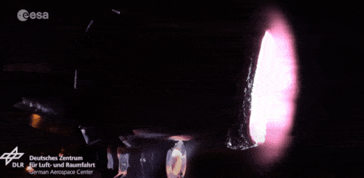
A simplified KARMA-4 model, with lower fidelity, was manufactured as a test sample for the demisability test. The test campaign was conducted in the L3K wind tunnel facility of DLR.
Some considerations that were done after the test campaign were that samples should always be as representative as possible: all simplifications must be considered carefully and justified by (demise testing) experience. In particular, the material can change the demise process, and whenever possible it should therefore be the same. Surface properties could also be impactful for the demise and shall be reproduced as correctly as possible.
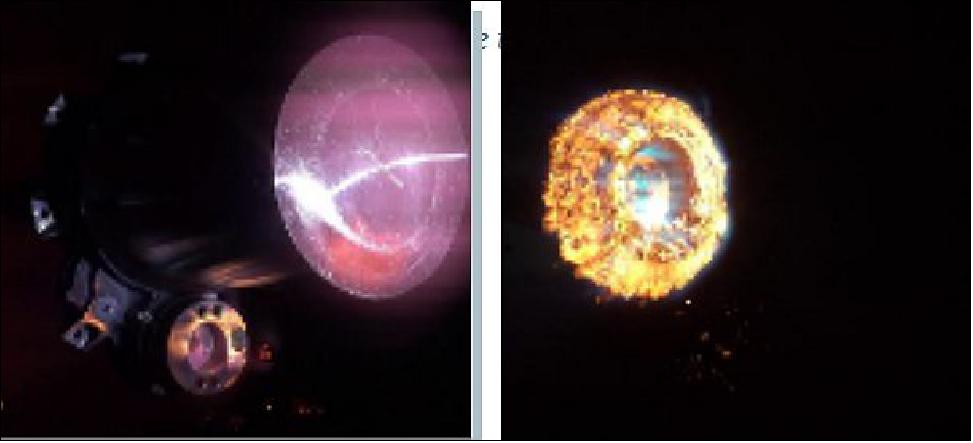
Figure 4: Video of the sample during the PWT test (video credit: DLR)
Test Correlation
After the test campaign, HTG correlated the test results with the simulations.
To rebuild the tests, some parameters in the simulations had to be adapted to match the test observations and demise timeline. In particular, it was necessary to take into account material properties uncertainties and in accordance with the values provided by the ESA ESTIMATE database, it was required to modify the material properties to their lowest allowed uncertainties range (following the ESA DIVE guidelines). In addition, to overcome the tools limitations on the simulations of the local heat flux effects, a slight increase of the heat flux was proposed, but it is generally not recommended.
To conclude, the tests show good demisability properties of the samples and the simulations resulted to be slightly conservative with respect to the tests. However this result should be seen taking into account the uncertainties in simulations and tests, as well as the simplifications in the sample characteristics with respect to the flight hardware.
The final task of this activity was for HTG to build a DRAMA model of the SADM, that will surely be the starting point to create an accurate model available to the users of the ESA DRAMA software in the future. The simplified model correlation was successfully achieved and it demonstrated the benefits of the implementation of the ESA DIVE guidelines. In particular the DIVE logic was successfully applied and an improvement of the document are expected in the near future.
In summary, this activity was carried out successfully, closely following the DIVE guidelines to ensure a standard approach to demise verification. Future studies should investigate higher fidelity test samples.
Lastly, due to the flexible nature of wires and cables, the harness has been excluded from the study, but it would be valuable to assess the impacts of harnesses on the overall demise phenomenology.
Drive to Destruction
As part of a larger effort called CleanSat, ESA is developing technologies and techniques to ensure future low-orbiting satellites are designed according to the concept of ‘D4D’ – Design for Demise. 2)
This Solar Array Drive Mechanism (SADM) has the essential task of keeping a satellite’s solar wings trained on the Sun, maintaining mission operations.
But its bulky nature presents a problem in terms of space debris guidelines. When a spacecraft reenters on an uncontrolled basis, the spacecraft operator has to prove that the on-ground casualty risk posed by its satellite is lower than 1 in 10 000.
So last year SADM manufacturer Kongsberg Defence & Aerospace (KDA) started an investigation supported by ESA, Hyperschall Technologie Göttingen GmbH (HTG) and the German Aerospace Center (DLR) to demonstrate the ‘desmisability’ of one of its satellite products.
They began by modelling such a reentry using ESA’s dedicated SCARAB (Spacecraft Atmospheric Reentry and Aerothermal Break-up) software and comparable resources, tweaking the SADM by switching one screw to lower-melting-point alumimium to promote an earlier, higher-altitude breakup.
Then their software model was compared to observed reality, by melting an actual SADM model inside DLR’s LK3 plasma wind tunnel in Cologne. Arc-heated gas in the test chamber reaching speeds of several kilometers per second, reproducing reentry conditions.
Following assessment of the results, HTG went on to build a model of the SADM using ESA’s DRAMA (Debris Risk Assessment and Mitigation Analysis) software tool, which will be available to other DRAMA users in the future.
References
1) ”Demising a SADM, in theory and practice,” ESA, 16 June 2021, URL: https://blogs.esa.int/cleanspace/2021/06/16/demising-a-sadm-in-theory-and-practice/
2) ”Drive to destruction,” ESA Enabling & Support, 15 June 2021, URL: https://www.esa.int/ESA_Multimedia/Images/2021/06/Drive_to_destruction
The information compiled and edited in this article was provided by Herbert J. Kramer from his documentation of: ”Observation of the Earth and Its Environment: Survey of Missions and Sensors” (Springer Verlag) as well as many other sources after the publication of the 4th edition in 2002. - Comments and corrections to this article are always welcome for further updates (eoportal@symbios.space).
Spacecraft Launch Mission Status Sensor Complement Ground Segment References Back to top