QBITO CubeSat
EO
Atmosphere
Mission complete
Imaging multi-spectral radiometers (vis/IR)
Quick facts
Overview
| Mission type | EO |
| Agency | UPM (Universidad Politécnica de Madrid) |
| Mission status | Mission complete |
| Launch date | 18 Apr 2017 |
| End of life date | 16 Feb 2019 |
| Measurement domain | Atmosphere |
| Measurement detailed | Neutral Particle Composition and Flow Velocity, Electron Energy and Pitch Angle Distribution |
| Instrument type | Imaging multi-spectral radiometers (vis/IR) |
QBITO
Spacecraft Launch Sensor Complement Ground Segment References
QBITO is the first CubeSat developed by students and faculty of UPM (Universidad Politécnica de Madrid), Spain. It is a 2U CubeSat and is part of the QB50 educational project, an EU funded project within FP7(Seventh Framework Program for Research), lead by the VKI (Von Karman Institute) of Brussels, Belgium. The main task of QBITO will be to operate the INMS (Ion Neutral Mass Spectrometer) which is the primary payload on-board the CubeSat and which will study the properties of the lower thermosphere. 1)
The QB50 mission consists of a network of 50 CubeSats in a ‘string-of-pearls' configuration. Forty of these CubeSats, including QBITO, will be deployed together from the ISS (International Space Station). The starting point of the mission will be a circular orbit at ~420 km altitude and 51.6º inclination, and due to atmospheric drag, the CubeSat orbits will decay until the spacecraft disintegrate in the atmosphere. The separation distance between CubeSats will increase during the mission, eventually leading to a non-uniform distribution of satellites all the way around the Earth.
This project development has a high educational interest for universities that, along with the scientific and technological results, provides an exciting opportunity to be part of an international group of over 90 universities from all over the world working and sharing knowledge to achieve a successful mission.
Mission goals: The QBITO mission encloses different goals related to both the QB50 project and university related advantages. The primary goals are:
• Comply with QB50 mission requirements
• Operate secondary payloads included by QBITO team
• Involve university students in the design and development of the CubeSat
• Test in-house developed equipment in real space mission conditions.
QB50 mission requirements were identified by QB50 consortium as the baseline to be followed by the teams. These requirements are based on the CubeSat standard and the main payload restrictions. 2)
Spacecraft
The CubeSat has been developed by the QBITO team which includes UPM staff, professors and students. This project is providing a valuable experience for everyone involved in it. It has given as well the opportunity to apply new design techniques. It is worth mentioning the use of the Object-Process Methodology, an emerging ISO standard that is being used for QBITO as the conceptual modelling framework at system engineering level. 3) 4)
The most distinguishing features of the QBITO platform are the new in-house developments present in the design. These include the structure, the Electrical Power Subsystem, the Communications subsystem and a novel antenna deployment mechanism. Those elements are complemented with COTS (Commercial Off-The-Shelf) units in order to reach a robust, yet innovative, architecture.
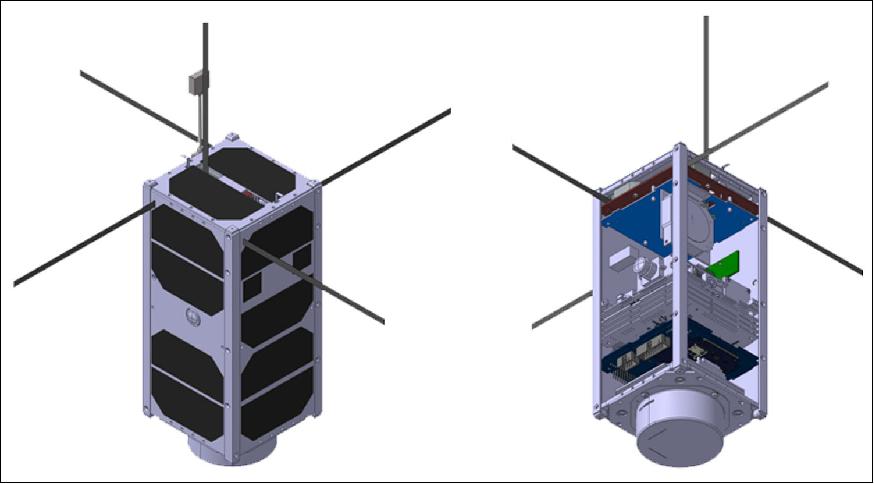
The INMS instrument was requested by QB50 to be placed in –Z face and the nominal attitude for its operation is requested to be such that the –Z axis points towards ram direction. The symmetry and the most favorable geometry configuration in terms of air drag torque in nominal attitude for the INMS operation have been taken into account. Figure 2 shows the block diagram where the general architecture of QBITO's subsystems with regards to power and data is presented. Indications are also presented for both analog and digital lines.
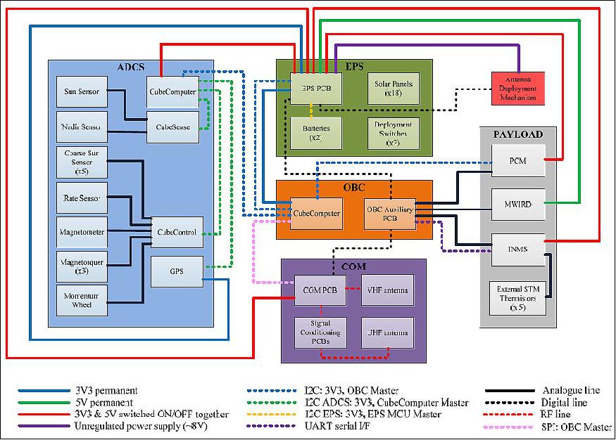
EPS (Electrical Power Subsystem): The EPS, including the solar panels, has been developed in-house obtaining a reliable subsystem that can cope with the requirements of typical CubeSat missions. Five faces of the satellite are covered by a total of 16 solar cells, leaving one of the faces free to be used by the INMS. Five MPPTs (Maximum Power Point Trackers) are being used, one per face. The power is regulated to the required voltage levels by the different equipment (3 V3 and 5 V) and distributed using dedicated switches. The battery voltage is also supplied for those units that need it, like the antenna deployment mechanism. Finally, the EPS is in charge of managing the charge and discharge processes of the set of two batteries selected for the mission with 2.85 Ah each. The EPS is available for the community through Theia Space.
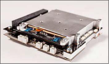
OBC (On-Board Computer): The CubeComputerV3, developed by Electronic Systems Laboratory, was selected by the QBITO team. The software has been developed in-house and developed in C; it is based on Free-RTOS.
ADCS (Attitude Determination and Control Subsystem): QBITO was granted by the QB50 consortium with one QB50 ADCS Bundle, developed by SSC (Surrey Space Center), Surrey, UK. The ADCS is based on the use of three magnetorquers (one per axis) and a momentum wheel. The processing unit will be a dedicated CubeComputer, equal to the one acting as OBC. Among the sensors are the sun sensors (1 fine and 5 coarse), 1 Earth sensor, 1 rate sensor, 1 magnetometer and 1 GPS receiver. The bundle has been specifically designed for this mission and has been verified against the attitude requirements imposed for QB50 project.
COM (Communications subsystem): The COM is based on a full duplex architecture with UHF for downlink and beacon, and VHF for reception. Transmission rates are 9.6 and 1.2 k bit/s for downlink and uplink, respectively. The subsystem makes use of transceivers configured by the OBC. The COM board is divided into two main parts, transmission (it includes the beacon) and reception. A four monopole turnstile antenna is being used for the downlink achieving circular polarization and omnidirectional pattern, whereas a VHF monopole is used for the uplink.
Antenna deployment mechanism: The antennas will be deployed with a novel deployment mechanism designed and developed in-house. Four equal mechanisms will be used for the deployment of the four monopoles that compound the UHF antenna. Another mechanism scaled to a larger dimension will be used for the deployment of the VHF antenna. The mechanism is based on a torsional spring which is rolled inside a cylinder (prior to deployment). This results in the antenna being pushed out and deployed. This mechanism is an optimized antenna deployment mechanism that fulfils the following requirements:
- Minimum impact in the lateral faces
- Minimum impact in volume, mass and cost
- Minimum number of parts in order to have maximum reliability
- Minimum number of manufacture tolerance.
TCS (Thermal Control Subsystem): The TCS is based on thermal coatings and paints. The thermal control design also includes two heaters that are in charge of maintaining the batteries within their operational temperature range. This copes with all the thermal loads which have been identified for the different operating scenarios for the QBITO mission.
Spacecraft
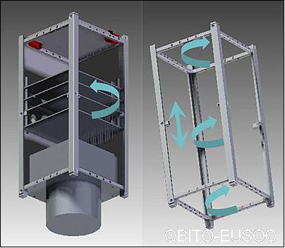
The structure has been developed in-house with the purpose of getting a lightweight multi-mission configurable structure. The technique used to do the conceptual design was based on applying the design theory "Entropy-Based Design" , which aims at selecting a concept that keeps as low as possible the number of internal dependencies. The result of applying this theory led to a solution that has the following characteristics:
- Maximum number of degrees of freedom, related to the possibility of changing the design
- Maximum flexibility, related to the possibility of adding new components
- Maximum number of translational and rotational symmetries, related to the possibility of moving components
- Maximum modularity related to the possibility of changing a component
- Minimum number of components, related to improvements in mass, cost, reliability, and power
- Maximum number of equal components, related to the reduction of cost.
The result is shown in Figure 4 where arrows indicate that three different 90º rotations are allowed, one translation along the Z-axis and one symmetry around the Z-axis. The result is a modular configuration with enough flexibility to satisfy the requirements of quite different missions. This structure is available for the community through Theia Space.
The QBITO CubeSat has a launch mass of ~ 1.8 kg.
Development Status
• The FRR (Flight Readiness Review) is scheduled for June 2016 (Ref. 1).
• The AIT (Assembly, Integration and Test) Readiness Review, was accepted in September 2015.
• The QBITO design passed a successful PDR and CDR in May 2013 and June 2014, respectively.
• November 2011 was the kick-off date for QB50 project. The QBITO proposal was submitted by the team in April 2012.
Launch
QBITO was launched on the Cygnus CRS-7 flight of Orbital ATK OA-7 (named John Glenn) on 18 April 2017 with an ULA Atlas 5 -401vehicle, contracted by NASA, to the ISS. Launch site: Space Launch Complex 41 at Cape Canaveral Air Force Station in Florida. Total cargo: 3380 kg. 5) 6)
At the least two airlock cycles will be used to complete the orbital deployment of QB50 and, according to the inputs from the Scientific Working Group, the constellation will be split into two batches. The second batch will be injected in orbit 90 days after the first one, allowing a better distribution of the satellite, to maximize the scientific return of the mission.
NanoRacks has been selected as a launch integration and deployment partner for the QB50 CubeSat Constellation Mission. NanoRacks will be deploying a majority of the QB50 satellites from the ISS utilizing the Company's NRCSD (NanoRacks CubeSat Deployer).
Orbit: The initial orbit of the CubeSats after deployment will be very similar to the one of the ISS with an expected altitude of ~400 km and an inclination of 51.6º. The QB50 CubeSats will orbit in the lower thermosphere (200-380 km) collecting scientific data, in what is considered by experts a relatively unexplored part of Earth's atmosphere.
Secondary Payloads
(38 CubeSats with a total mass of 83 kg)
• Altair-1, a 6U CubeSat of Millennium Space Systems, El Segundo, CA
• IceCube, a NASA (GSFC 3U CubeSat technology demonstration mission.
• HARP, a 3U CubeSat of UMBC (Uni. of Maryland, Baltimore County)
• CSUNSat-1, a 2U CubeSat of CSUN (Cal. State University, Northridge)
• CXBN-2, a 2U CubeSat of Morehead State University, Kentucky.
• Open, a 1U CubeSatof UND (University of North Dakota), USA.
• Violet, a 1U CubeSat of Cornell University, Ithaca, N.Y., USA.
• Biarri-Point, a 3U CubeSat of Australia, USA, UK and Canada.
• KySat-2, a 1U CubeSat of the University of Kentucky and Morehead State University, USA.
• Lemur-4 x 4, 3U CubeSats of Spire Global Inc. (Lemur constellation), San Francisco, CA, USA.
The following 28 CubeSats are of the international QB50 constellation.
• SuSat, a 2U CubeSat of the University of Adelaide, Australia, part of QB50
• UNSW-EC0, an Australian 2U CubeSat of the Australian Center for Space Engineering Research at the University of New South Wales.
• INSPIRE-2, an Australian 2U CubeSat of the University of Sydney participating in the QB50 project.
• ZA-AeroSat is a 2U CubeSat of Stellenbosch University, South Africa.
• nSIGHT-1, a 2U CubeSat of SCS-Space, South Africa.
• Ex-Alta-1, a 3U CubeSat of the University of Alberta, Canada.
• LilacSat-1, a 2U CubeSat of Harbin Institute of Technology, China.
• NJUST-1, a 2U CubeSat of NJUST (Nanjin University of Science and Technology), China.
• AoXiang-1, a 2U CubeSat of SELM (Shaanxi Engineering Laboratory), China.
• SOMP-2, a 2U CubeSat of TU Dresden, Germany.
• QBITO, a 2U CubeSat of the Polytechnic University of Madrid, Spain.
• Aalto.2, a 2U CubeSat of Aalto University, Aalto, Finland.
• X-CubeSat-1, a 2U-CubeSat of École polytechnique, France.
• SpaceCube, a 2U CubeSat of Mines ParisTech, France.
• DUTHSat, a 2U CubeSat of Democritus University of Thrace (DUTH), Greece.
• UPSat, a 2U CubeSat of the Patras and Libre Space Foundation, Greece.
• Hoopoe, an Israeli 2U CubeSat.
• LINK (Little Intelligent Nanosatellite of KAIST), a 2U CubeSat of KAIST, Korea.
• SNUSAT-1 and -1B (Seoul National University Satellite-1), 2 x 2U CubeSat of Seoul National University, Korea.
• qbee50-LTU-OC, a 2U CubeSat of LTU (Luleå Tekniska Universitet), Sweden.
• BeEagleSat, a 2U CubeSat of Istanbul Technical University and Turkish Air Force Academy, Turkey.
• HAVELSAT, a 2U CubeSat of HAVELSAN and Istanbul Technical University, Turkey.
• Phoenix, a 2U CubeSat of National Cheng Kung University (NCKU), Taiwan.
• PolyITAN-2-SAU, a 2U CubeSat of the National Technical University of Ukraine, Ukraine.
• QBus-1, a 2U CubeSat of University of Colorado, Boulder, USA
• QBus-2, a 2U CubeSat of the University of Michigan, USA.
• QBus-4, a 2U CubeSat of the Universidad del Turabo, Puerto Rico, USA.
Sensor Complement
Apart from the INMS, QBITO will carry three other payloads in order to take advantage of the mission as much as possible. The first experiment, the MWRID (Medium Wave Infrared Detector), is developed by the Spanish company New Infrared Technologies and aims at testing a novel kind of uncooled detectors, in space conditions. The second is an experiment that will assess the performance of the Docosane as a PCM (Phase Change Material). It is being developed in collaboration with the University of Liège. Finally, the third additional payload, developed at UPM is the ESW (Experimental Software). It implements an attitude determination and control algorithm based on fuzzy control theory. The purpose is to test the suitability of this kind of control technique for spacecraft attitude control applications.
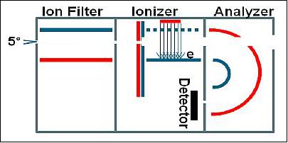
INMS (Ion Neutral Mass Spectrometer)
INMS is the prime instrument of QBITO. It is in charge of taking in-situ measurements to characterize the composition of ions and neutral particles and their spatial variation. The INMS is a miniaturized analyzer designed for sampling of low mass ionized and neutral particles in the spacecraft ram direction with the instrument resolutions optimized for resolving the major constituents in the lower thermosphere, i.e., O, O2, N2. The INMS development is being carried out by UCL/MSSL (University College London/Mullard Space Science Laboratory, Ref. 2).
The key sensor components consist of a collimator/ion filter, an ionizer and a charged particle spectrometer. Particles enter the aperture into the ion filter region where charged particles can be rejected. This is followed by a series of baffles for collimation and further charged particle suppression. Collimated neutral particles are subsequently ionized in the ionizer by a 50 eV electron beam followed by mass selection in the analyzer. With an energy resolution of 3%, the analyzer will provide clean separation of the major constituents. The spectrometer can be operated in different modes, optimized for ions or neutral particle analysis.
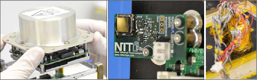
MWIRD (Medium Wave Infrared Detector)
The MWIRD is an experiment that will test the behavior in space of an uncooled medium wave infrared detector based on the new VPD (Vapor Phase Deposited) PbSe technology. The experiment has been designed by NIT (New Infrared Technologies), a Spanish company developer of this technology.
PCM (Phase Change Material)
The objective of the PCM experiment is to test the performance of n-Docosecane as a useful phase change material for future use in space thermal control systems. The experiment has been developed by UPM in collaboration with the University of Liege, Belgium. A flight experiment is mandatory to increase the TRL of this technology. 7)
ESW (Experimental Software)
ESW is an attitude determination and control software that will be tested on QBITO, taking advantage of the hardware included in Surrey's QB50 ADCS Bundle. It has been developed by UPM at E-USOC (User Support and Operations Center, Spain). It aims at demonstrating novel fuzzy control techniques in orbit. It is expected to validate separately the orbit and attitude determination module and the attitude control module. Among the benefits that can be expected from the ESW development, there is the use of a more powerful controller, which deals easily with inaccuracies of the satellite model and that can be quite easily adaptable to other missions. Also, it is expected that it will improve the performances while reducing the power consumption of the whole subsystem.
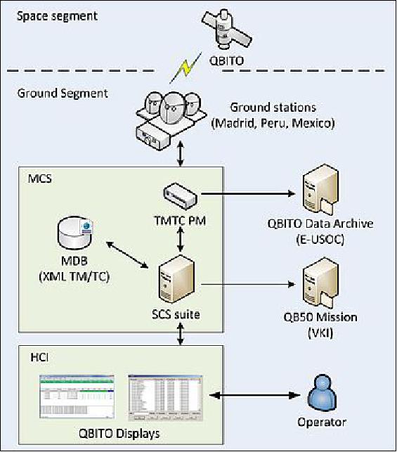
Ground Segment
The ground segment for the QBITO mission is composed of the following elements:
• Four ground stations, which will be the interface to communicate with the spacecraft. Two of them are placed in Madrid at E-USOC (ETSIAE, UPM) and ETSIT (UPM) and the other two are placed in Lima, Peru (UNI) and Mexico City, Mexico (UNAM).
• The MCS (Mission Control System), to support the operations and AIV phases. The MCS comprises two different software units and a database:
- A TMTC Packet Manager (PM)
- The Satellite Control Software (SCS)
- The Mission Database (MDB).
• Human Control Interface (HCI), used to monitor and command the spacecraft.
• One File Server for the mission data archival, located at E-USOC.
The ground station at E-USOC has already tracked the precursor CubeSats launched in the frame of QB50 project. Telemetry has been successfully downlinked and an uplink test is scheduled for May 2016, where some telecommands will be sent to the satellites in order to test the uplink capacity.
References
1) Ignacio Barrios Tascón, Ana Laverón Simavilla, Efrén Moreno Benavides, "Test campaign of QBITO CubeSat," Proceedings of the 4S (Small Satellites, System & Services) Symposium, Valletta, Malta, May 30-June 3, 2016, URL: http://congrexprojects.com/docs/default-source/16a02_docs/4s2016_final_proceedings.zip?sfvrsn=2
2) R A Chaudery, "QB50 INMS Science Unit Interface Control Document," Issue 13, UCL (University College London, Nov. 23, 2015
3) "The QBITO CubeSat," URL: http://www.eusoc.upm.es/en/projects/qb50.html
4) Ignacio Barrios Tascón, "QBITO Development and Students Involvement," 1st SSEA (Syposium on Space Educational Activities), Padova, Italy, 9-12 December, 2015, URL: http://cisas.unipd.it/sites/cisas.unipd.it/files/A4-Barrios-PRESENTATION.pdf
5) "Mission Page: OA-7 Space Station Cargo Resupply," Orbital ATK, April 18, 2017, URL: https://web.archive.org/web/20170224064116/https://www.orbitalatk.com/news-room/feature-stories/OA7-Mission-Page/default.aspx?prid=180
6) "NanoRacks to Deploy QB50 Satellites from International Space Station," NanoRacks, March 9, 2016, URL: http://nanoracks.com/deploy-qb50-satellites-from-iss/
7) Benoit Delcroix. Michaël Kummert, Ahmed Daoud, Jonathan Bouchard, "Influence of experimental conditions on measured thermal properties used to model phase change materials," Building Simulation, December 2015, Volume 8, Issue 6, pp 637-650, URL of abstract: http://link.springer.com/article/10.1007/s12273-015-0241-8
The information compiled and edited in this article was provided by Herbert J. Kramer from his documentation of: "Observation of the Earth and Its Environment: Survey of Missions and Sensors" (Springer Verlag) as well as many other sources after the publication of the 4th edition in 2002. - Comments and corrections to this article are always welcome for further updates (eoportal@symbios.space).
Spacecraft Launch Sensor Complement Ground Segment References Back to top