POPSAT-HIP1 (Propulsion Operation Proof SATellite – High Performance 1)
Non-EO
Operational (nominal)
Quick facts
Overview
| Mission type | Non-EO |
| Mission status | Operational (nominal) |
| Launch date | 19 Jun 2014 |
POPSAT-HIP1 (Propulsion Operation Proof SATellite – High Performance 1)
Overview Spacecraft Launch Experiment Complement Mission Status References
POPSAT-HIP1 is a 3U CubeSat featuring a proprietary micropropulsion system for nanosatellites, which was designed and developed at Microspace Rapid Pte Ltd of Singapore. The objective is to demonstrate the functionality of multiple integrated payloads in orbit. 1)
Overview
Micropropulsion is one of the latest of the building blocks on the way to become a standard feature of small satellites, nanosatellite and CubeSats. The topic has been explored by several groups and some experiments have been performed in orbit although they have been usually short lived or used as preliminary assessment or partial demonstration only. 2) On the other hand the literature on laboratory experiments or just conceptual designs is very vast almost suggesting that the topic is already a mature one. Certainly the intrinsic difficulties of realizing a micropropulsion system actually working in Space have been the cause of the delayed arrival of this technology on a real, long-lived, orbiting nanosatellite.
Among such difficulties, the project at Microspace does not only the need to use very special manufacturing technologies for the construction of the micronozzles, but also the real or assumed resistance of launchers to allow the presence of a propellant on a class of satellites which is still perceived as a toy or just as an immature product that, because of lack of testing, may produce damages to the other elements of the mission.
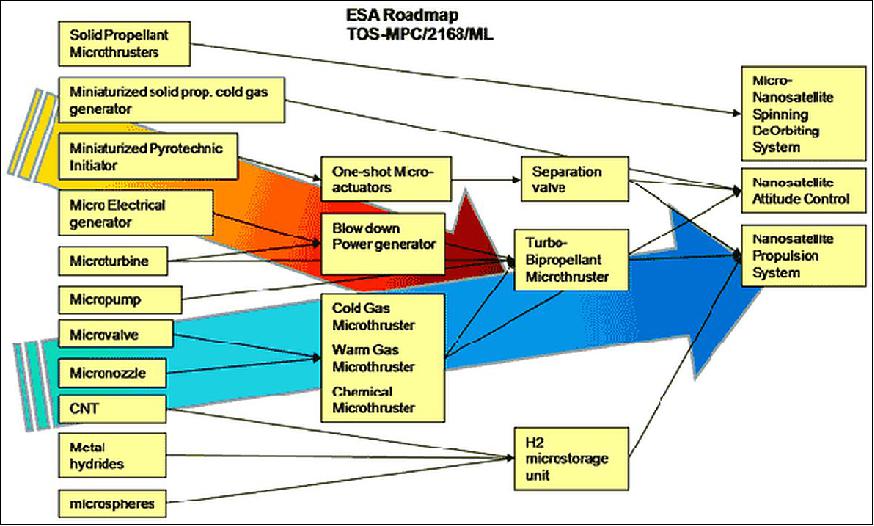
Microspace has been dealing with such issues one by one since the beginning of activities in year 2002, and has pursued a roadmap of development as shown in Figure 1 that was also adopted by ESA in its harmonization document. 3) 4)
The POPSAT-HIP1 project focused initially on the development of the essential and unique element, which is the core of any micropropulsion system: the micronozzle, a high efficiency microfluidic device with micrometer sized features and sub-micrometer surface qualities. The project went through 3 phases of development: technology feasibility demonstration, technology refinement and full scale engineering production involving facilities in Italy, Japan, and Singapore.
Once the micronozzle, its controls, and its characterization devices were completed,the project moved to the development of the complete micropropulsion system, made in a modular fashion to fit into a 1U CubeSat and to be scaled up to the nanosatellite and microsatellite classes. This represented the start for the development of POPSAT-HIP1 (Propulsion Operation Proof SATellite – High Performance 1) project in 2010, to achieve an in-orbit demonstration. Initially, the launch was planned for 2012, but the launch arrangement for a Dnepr vehicle postponed this goal to June 2014.
Spacecraft
POPSAT-HIP1 is a 3U CubeSat with a mass of 3.3 kg. Its primary payload is built around the Microspace micropropulsion system for attitude control with 6 micronozzles modules placed on the edges of the front face and 2 micronozzles placed along one of the long sides of the satellite as illustrated in Figure 2.
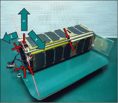
One of the control axes has redundant nozzles that can be used also to produce a net force for possible formation flight. Such a configuration has been chosen to maximize the arm of the nozzles while occupying the least possible volume. All satellite electronics are arranged to occupy 1U of the satellite while the rest of the 2U are utilized for a pressurized tank containing Argon gas at about 8 bar. The tank is completely customized and integrated in the secondary payload of the satellite for the most efficient use of the available volume.
The satellite is equipped with fixed and deployable solar panels and its primary attitude determination and control system is based on magnetorquers, magnetometers, sun sensors and gyroscopes. The communication is achieved by a UHF half-duplex transceiver using a simple deployable dipole antenna.
Launch
The POPSAT-HIP1 nanosatellite was launched as a secondary payload on June 19, 2014 (19:11:11 UTC) on a Dnepr-1 vehicle of ISC Kosmotras. The launch site was the Yasny Cosmodrome in the Dombarovsky region of Russia.
The primary payloads on this flight were Deimos-2 (~310 kg) of Deimos Imaging S.L.U., Spain and the KazEOSat-2 minisatellite (~185 kg) of KGS (National Company Kazakhstan Garysh Sapary), Kazakhstan. 5) 6) 7) 8)
Orbit
Sun-synchronous orbit, nominal altitude of 630 km, inclination = 98º, LTAN (Local Time of Ascending Node) of 10:30 hours.
Secondary Payloads (35) on this Dnepr Cluster Mission 9)
• UNISat-6, a microsatellite of GAUSS at the University of Rome (La Sapienza), Italy. UniSat-6 (26 kg) includes Pico-Orbital Deployers and PEPPODs (Planted Elementary Platform for Picosatellite Orbital Deployment) systems for the release of four CubeSats from the spacecraft. These four satellites are:
- Lemur-1, a 3U CubeSat (technology demonstration and EO) of NanoSatisfi Inc., San Francisco, CA, USA
- TigriSat, a 3U CubeSat of the University of Rome (La Sapienza), Rome, Italy.
- ANTELSAT, a 2U CubeSat of UdelaR (University of the Republic), San Marino, Uruguay
- AeroCube-6, a 1U CubeSat of The Aerospace Corporation, El Segundo, CA.
• SaudiSat-4 a microsatellite (112 kg) of KACST (King Abdulaziz City for Science and Technology) with input from NASA/ARC.
• AprizeSat-9 and -10, nanosatellites (each of 12 kg) of SpaceQuest, USA. AprizeSat-10 carries an AIS (Automatic Identification System) receiver for ship tracking.
• Hodoyoshi-3 and -4, microsatellites (60 kg and 65 kg, respectively) of the University of Tokyo and JAXA/ISAS, Japan
• BRITE-CA-1 and BRITE-CA-2, two nanosatellites (7 kg each) of UTIAS/SFL (University of Toronto, Institute for Aerospace Studies), Toronto, Canada
• TabletSat-Aurora, a microsatellite (25 kg) of SPUTNIX, Russia
• BugSat-1, a microsatellite (22 kg) of Satellogic S.A., Argentina
• Perseus-M1 and M2, two identical 6U CubeSats of Canopus Systems US / Dauria Aerospace. The nanosatellites are carrying an AIS payload for ship tracking.
• QB50P1 and QB50P2, two 2U CubeSats (2 kg each) of Von Karman Institute, Brussels, Belgium. These are two precursor satellites to the QB50 project that will launch a network of 50 satellites by a team of 15 universities and institutions around the world.
• NanoSatC-Br1, a 1U CubeSat of the Southern Regional Space Research Center and of INPE, Brazil
• DTUSat-2, a 1U CubeSat of DTU (Technical University of Denmark), Lyngby, Denmark
• POPSAT-HIP1, a 3U CubeSat of Microspace Rapid Pte Ltd., Singapore
• PolyITAN-1 of KPI (Kiev Polytechnic Institute), Kiev, Ukraine
• PACE (Platform for Attitude Control Experiments), a 2U CubeSat (2 kg) of NCKU (National Cheng Kung University), Tainan City, Taiwan
• Duchifat-1, a 1U CubeSat of HSC (Herzliya Science Center), Israel
• 11 Flock-1c nanosatellites (eleven 3U CubeSats, 5 kg each) of Planet Labs, San Francisco, CA.
Orbit
Sun-synchronous orbit, nominal altitude of 630 km, inclination = 98º, LTAN (Local Time of Ascending Node) of 10:30 hours.
Experiment Complement
CGMS (Cold Gas Micropropulsion System)
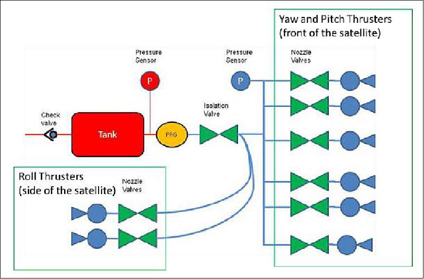
CMGS utilizes 8 micronozzles of 1mN nominal thrust at 5 bar of Argon propellant. Each nozzle has been individually characterized on a microbalance built in house and operated in a vacuum chamber. Each nozzle is operated via an electromagnetic microvalve with a minimum opening time of 1ms - and an unlimited opening time. The nozzles are fed via a low pressure manifold circuit which is connected to the main tank through a pressure regulator and an isolation valve. Pressures in the tank and on the nozzle supply line are measured by MEMS pressure sensors. Figure 3 shows the block diagram of the overall system.
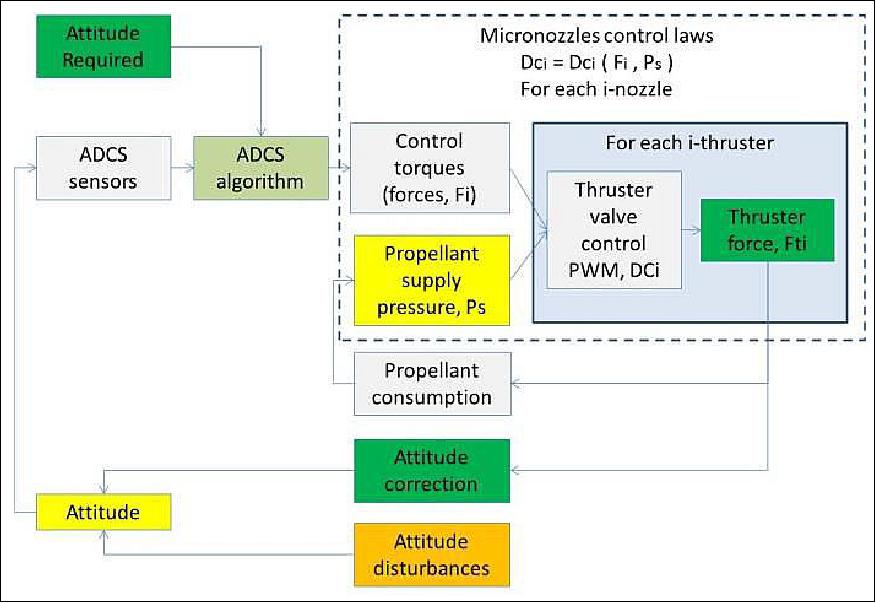
The control of the micropropulsion system, as shown in Figure 4, is integrated on the ADCS (Attitude Determination and Control Subsystem) algorithm of the nanosatellite. Based on the knowledge of the present attitude and the required attitude, the control torque can be calculated based on the available propellant pressure. The calculation can then be translated to the required duty cycle to produce the average force, which then affects the attitude of the spacecraft and reduces the available propellant. The new information is then fed back into the control and the calculation loop restarts.
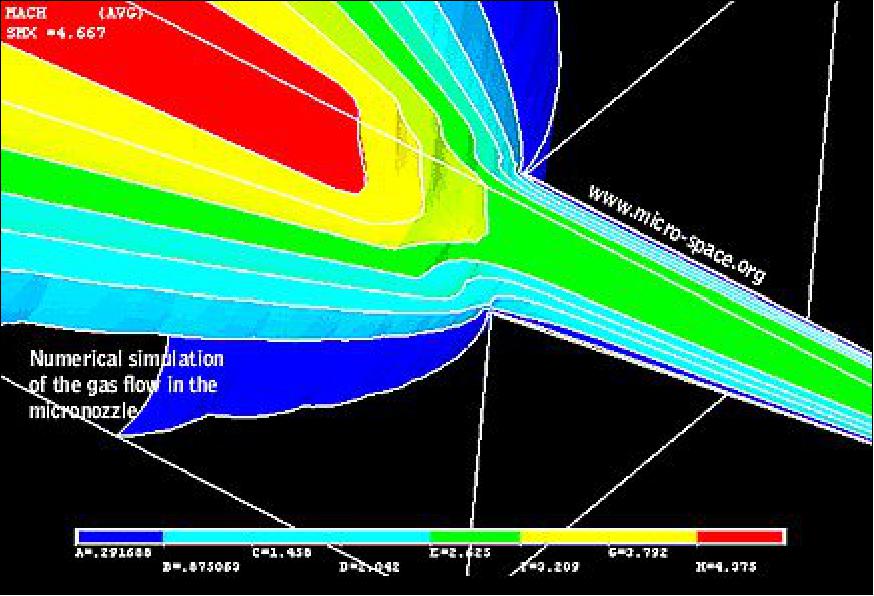
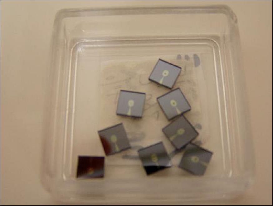
Supersonic Micronozzle
The supersonic micronozzles are produced by MEMS processes called "Microlithography, Deep Reactive Ion Etching, Anodic Bonding and Dicing". The nozzles have been developed through a comprehensive project including CDF (Computational Fluid Dynamics) by finite elements analysis, microfabrication, and vacuum microbalance characterization of several different shapes to obtain the optimal geometry as presented in Figures 5 and 6. 10)
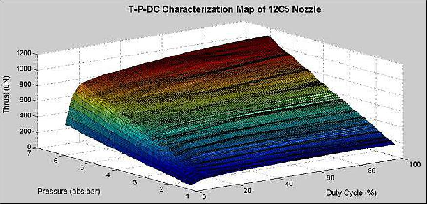
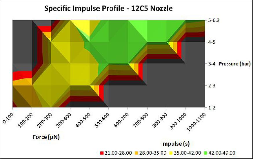
Each nozzle has been individually characterized on a microbalance built in house and operated in a vacuum chamber. Characterization includes mapping the nozzle thrust and specific impulse over the whole range of available pressure and microvalve opening control (i.e. duty cycle) in order to obtain the functions mapping of nozzle performances that are later utilized by the thrust control loop combined with the attitude control algorithms (Ref. 10).
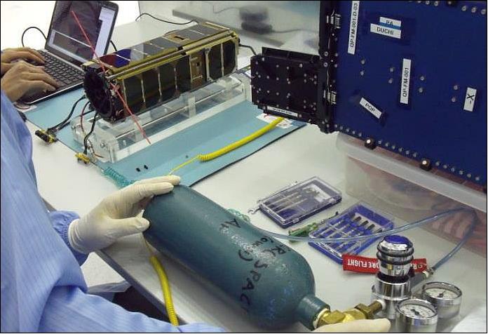
Propellant Pressure Profile
The tank system (i.e. high-pressure chamber) has been filled during the final check out operations at the Yasny base just before inserting POPSAT into the Quadpack deployment system provided by ISL. The pressure stability has been monitored for 2 days to confirm the absence of leakages. For safety reasons and to minimize any risk, the pressure has been limited to 7.8 bar even if the system can work up to 18 bar with the present design. 11)
The satellite was launched 2 weeks later and micropropulsion operations have been conducted by telecommands from the Microspace Ground Station of Singapore. After initial verification of the satellite good condition during the first few days in orbit, the isolation valve has been opened and the increase in pressure of the low-pressure chamber is shown in Figure 10.
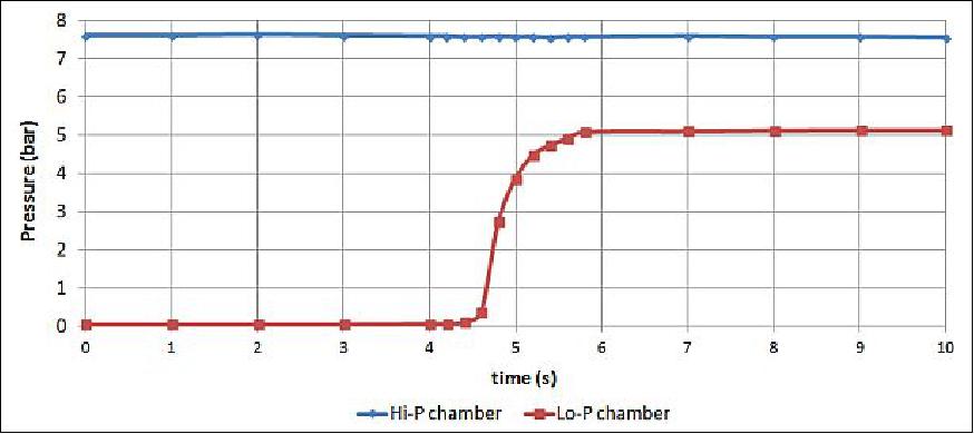
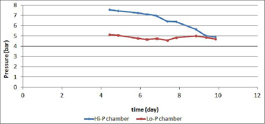
Figure 12 shows the pressure profile of POPSAT since the opening of the isolation valve to the time of this article writing. Many micropropulsion experiments were heavily attempted in the first ten days and the corresponding reduction in pressure is shown in Figure 11. Nevertheless, due to an unexpected software bug in the gyroscopes initialization, the micropropulsion effect could not be verified with the necessary accuracy. It should be noted that the pressure in the low pressure chamber varies around the set point of 5 bar due to the pressure regulator internal adjustments.
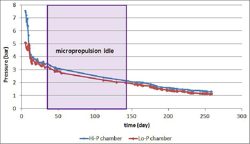
The micropropulsion experiment resumed 150 days later after a problem with the satellite internal I2C bus had been resolved. It can be seen from the pressure profile, that the observed leakage of the low pressure chamber is 8 mbar/day. Conservatively assuming a linear relationship, it will take another 170 days for the pressure to drop to 0.5 bar, which can be considered the lower limit of the micropropulsion effectiveness.
Analysis of an Angular Velocity Change Maneuver
The angular velocity change is the simplest maneuver. It is achieved by firing one thruster in the desired direction. The inertia of the satellite is given in Table 1 along with the arm of the thrusters with respect to the COM (Center of Mass) which is known by design and has been verified by means of balancing the satellite before the launch with an uncertainty of ~2 mm.
Inertia | Unit | Value |
Mass | kg | 3.3 |
Px | kgm2 | 0.043 |
Py | kgm2 | 0045 |
Pz | kgm2 | 0.009 |
Magnetometers | Reference axis | Max. dipole moment – at 25ºC (Am2) |
A | X axis | 0.145 |
B | Y axis | 0.145 |
C | Z axis | 0.110 |
Thrusters | Reference axis | Arm to COM (m) |
S4 | +X axis | 0.167 |
12B5 | +X axis redundant | 0.052 |
7C5 | +Y axis | 0.180 |
V4 | +Z axis | 0.061 |
7E5 | –X axis | 0.167 |
V5 | –X axis redundant | 0.052 |
12C5 | –Y axis | 0.180 |
V1 | –Z axis | 0.061 |
A maneuver starts by ensuring that the gyroscopes are active, followed by powering the valves controller board through a series of telecommands, and by measuring the gas pressure in the tank to confirm the health of the system. The angular velocities of the satellite are subsequently measured repeatedly by means of the gyroscope readings to choose the firing direction. The maneuver attempt was initiated with a tumbling test to show that the micronozzle was really able to fire and cause angular velocity change of the satellite. The attempt examples can be seen in Figures 13 and 14.
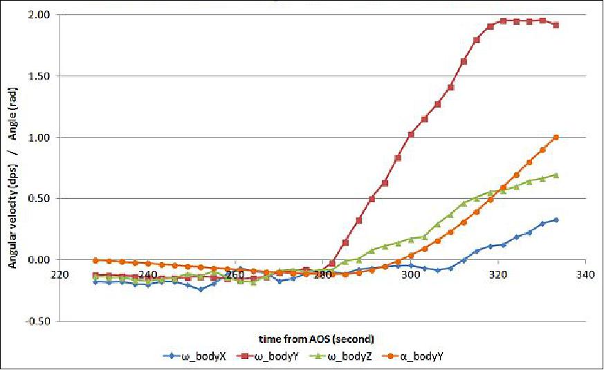
Subsequently, it is for example interesting to stop a particular angular velocity in order to prepare for a clean attitude change maneuver as illustrated in Figures 15 and 16.
One simple example to discuss is the test conducted on 28 November 2014 as illustrated in Figure 13. The initial velocity of Y axis was -0.1º/s and after a firing attempt in the +Y axis, at a setting of 90% duty cycle for 30 seconds, the final velocity was 1.95º/s. This confirms the correct functioning of the +Y axis thruster.
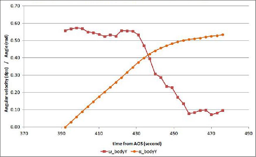
Another example is the test on 9 January 2015 as illustrated in Figure 15. In this case, the purpose was to stabilize the satellite due to its tumbling state. The initial velocity of the Y axis was 0.55º/s and after a firing attempt in the -Y axis, at a setting of 4% duty cycle for 10 seconds, followed by 2% duty cycle for another 10 seconds, the final velocity was 0.09º/s, which is generally sufficient within the resolution of the gyroscope to start a meaningful attitude change maneuver as described in the next paragraphs.
It should be noted that the gas consumption for each propulsion attempt is very minimal and cannot be measured just by evaluating the pressure difference before and after the maneuver. Therefore, only after several maneuvers can the average gas consumption be estimated.
Depending on the available pressure in the tank, a different thrust will be available at varied valve duty cycle as already presented in Figure 7. The thrust needed to obtain the necessary velocity change is then calculated and the corresponding duty cycle is determined by the mapping of thrusters calibrations as performed in the laboratory. The necessary telecommand is sent to the satellite and after execution, the new velocity is acquired from the gyroscope readings.
Table 2 shows the log of such maneuvers in several different objectives. Tumbling and detumbling tests are to show that the micropropulsion works in the particular axis, while a bang-bang maneuver is to show that the satellite can be rotated according to the desired velocity and return to its stabilized state. The target pointing simulation is to show that the satellite is able to keep pointing at a certain target by keeping adjusting its velocity by means of micropropulsion. The tests were kept in single axis control due to its simplicity in showing the effect of the micropropulsion.
Date | Pressure (bar) | Firing axis | DC (5) | Duration (s) | Δω (º/σ) |
21.11.2014 | 1.85 | +Z | 90 | 20 | 0.38 |
24.11.2014 | 1.85 | -Z | 90 | 20 | 0.34 |
26.11.2014 | 1.83 | -Y | 90 | 60 | 2.72 |
28.11.2014 | 1.78 | +Y | 90 | 30 | 2.05 |
14.12.2014 | 1.62 | -Y | 90 | 40 | 1.80 |
15.12.2014 | 1.61 | +Y | 90 | 30 | 1.65 |
16.12.2014 | 1.60 | -X short arm | 90 | 60 | 0.74 |
18.12.2014 | 1.56 | +X | 90 | 30 | 1.18 |
23.12.2014 | 1.48 | +X | 90 | 30 | 1.73 |
09.01.2015 | 1.36 | -Y | 4 | 10 | 0.31 |
27.01.2015 | 1.30 | +X | 90 | 20 | 0.8 |
28.01.2015 | 1.28 | -X | 80 | 20 | 0.6 |
+X | 8 | 10 | 0.35 | ||
-X | 60 | 10 | 0.54 | ||
01.02.2015 | 1.21 | +Y | 2 | 10 | 0.21 |
4 | 10 | 0.24 | |||
10 | 10 | 0.46 | |||
-Y | 60 | 10 | 0.36 | ||
10 | 10 | 0.30 | |||
5 | 10 | 0.25 | |||
2 | 10 | 0.19 | |||
01.03.2015 | 1.15 | +Y | 2 | 10 | 0.20 |
4 | 10 | 0.27 | |||
8 | 10 | 0.38 | |||
-Y | 10 | 10 | 0.34 | ||
5 | 10 | 0.24 | |||
2 | 10 | 0.20 |
Analysis of an Attitude Change Maneuver
The attitude change maneuver is a typical bang-bang action with firing a certain number of times a given thruster followed by a waiting time and then firing the opposite thrusters for the necessary number of times. At the beginning of life, when the pressure in the tank is still rather high, one firing at low duty cycle may be sufficient, depending of the desired speed of attitude change, while towards the end of life, multiple firings at 100% duty cycle will be necessary if a fast attitude change is desired. Table 3 and Figure 17 illustrates the expected change in the satellite angular velocity at a given pressure and firing duration for the –Y axis.
For example, at 2 bar of available pressure, a firing of 10 s at 90% duty Cycle should produce a Δω on the Y axis of about 0.6º/s.
Δω (º/σ) | Time (second) | |||||
P (bar) | F (µN) | 5 | 10 | 20 | 40 | 60 |
1.0 | 83 | 0.10 | 0.19 | 0.38 | 0.76 | 1.14 |
1.6 | 204 | 0.23 | 0.47 | 0.94 | 1.87 | 2.81 |
2.0 | 280 | 0.32 | 0.64 | 1.28 | 2.55 | 3.83 |
3.0 | 470 | 0.54 | 1.08 | 2.17 | 4.34 | 6.51 |
4.0 | 670 | 0.77 | 1.53 | 3.06 | 6.13 | 9.19 |
5.0 | 860 | 0.99 | 1.98 | 3.96 | 7.93 | 11.9 |
6.0 | 1100 | 1.21 | 2.43 | 4.85 | 9.70 | 14.6 |
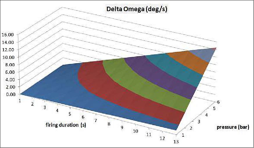
Figure 18 shows a maneuver executed after 6 months of life in orbit, when the available gas pressure was already reduced down to about 1.6 bar. A rotation of 160º has been achieved in about 3 minutes time with a total firing time of 70 seconds by means of 4 times firing of the –Y axis thruster at 90% duty cycle and 3 times firing of the +Y axis thrusters at the same 90% duty cycle.
The observed change of angular velocity in the –Y axis was 1.8º/s, corresponding to 0.45º/s per firing. Based on the expected values shown in Table3, a pressure of 1.62 bar corresponds to an expected 0.47º/s, indicating a well characterized micronozzle of only a reduction of about 4% in the overall effectiveness of the maneuver. Based on Figure 8, it can subsequently be estimated, that for this maneuver at low operative pressure, the specific impulse was 34 s.
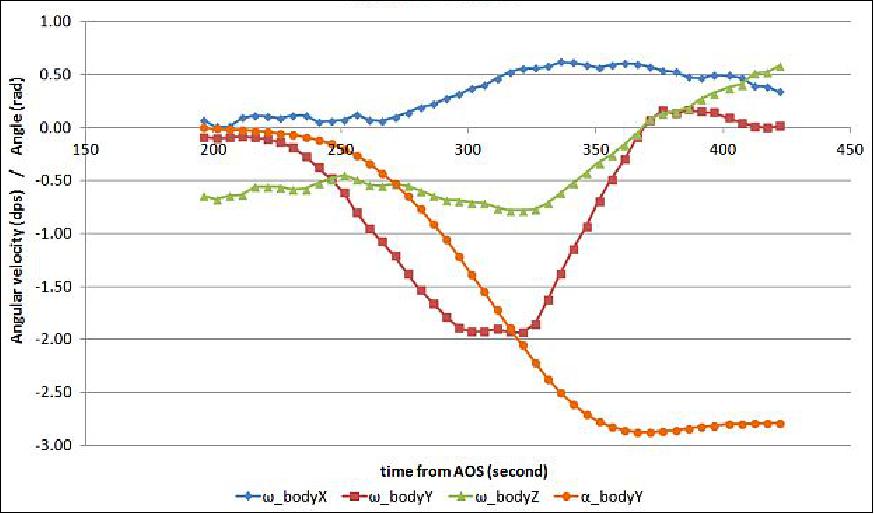
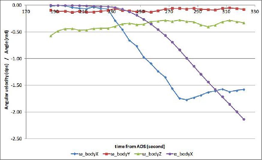
Another rotation of 130º has also been achieved in a total firing time of 60 seconds by means of 3 times firing of the +X axis thruster at 90% duty cycle and 5 times firing of the –X axis thrusters at the same 90% duty cycle. The shorter duration of the +X axis firing is due to the longer arm of the microthruster located in that particular axis.
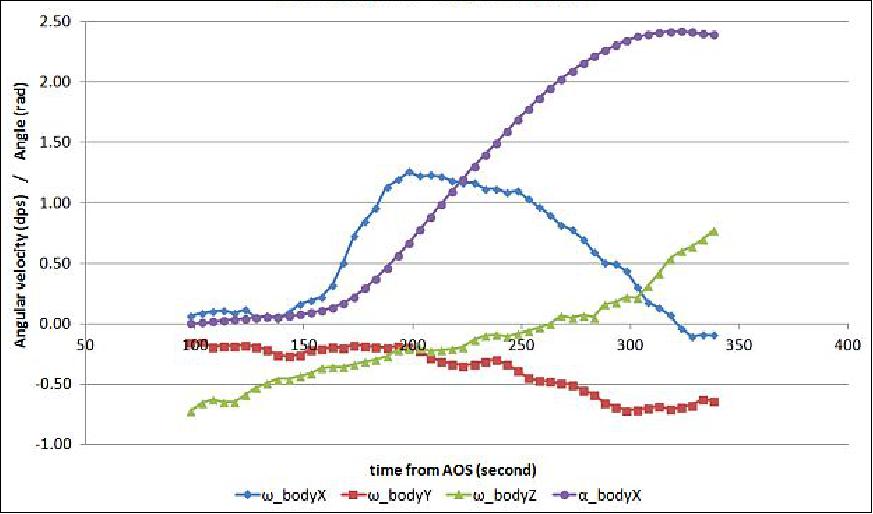
The observed change of angular velocity in the +X axis was 1.18º/s, corresponding to 0.39º/s per firing. Having a pressure of 1.56 bar, it corresponds to an expected 0.42º/s, indicating a reduction of about 7% in the overall effectiveness of the maneuver. It can be estimated that for this maneuver at low operative pressure, the specific impulse was 33 s.
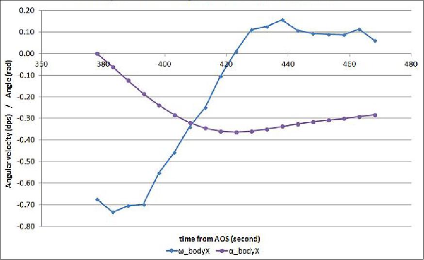
Figures 20 and 21 show another example of bang-bang maneuver that specifically used to reproduce a target pointing activity, however only in single axis. In this case, different duty cycles were applied over the period range that the satellite has to keep pointing at a specific target.
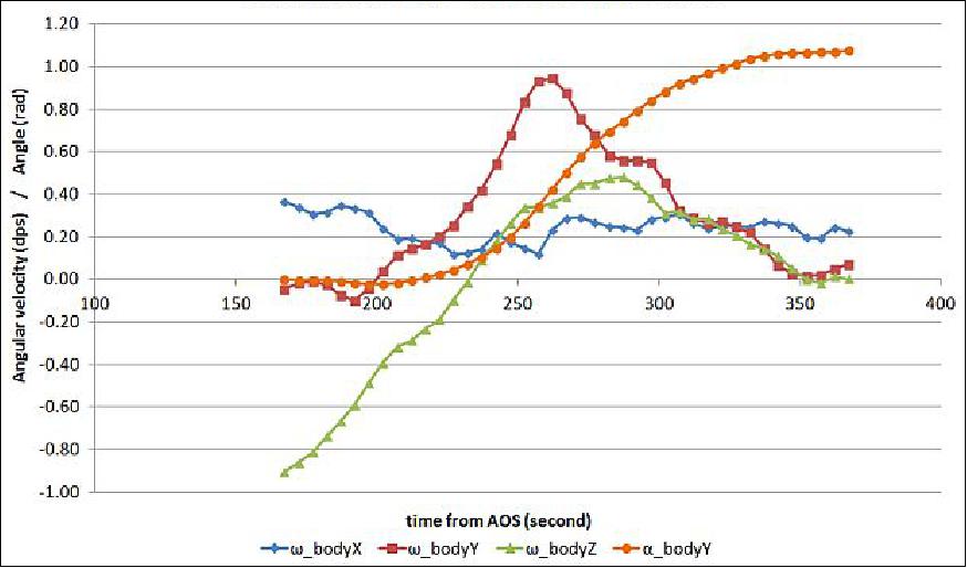
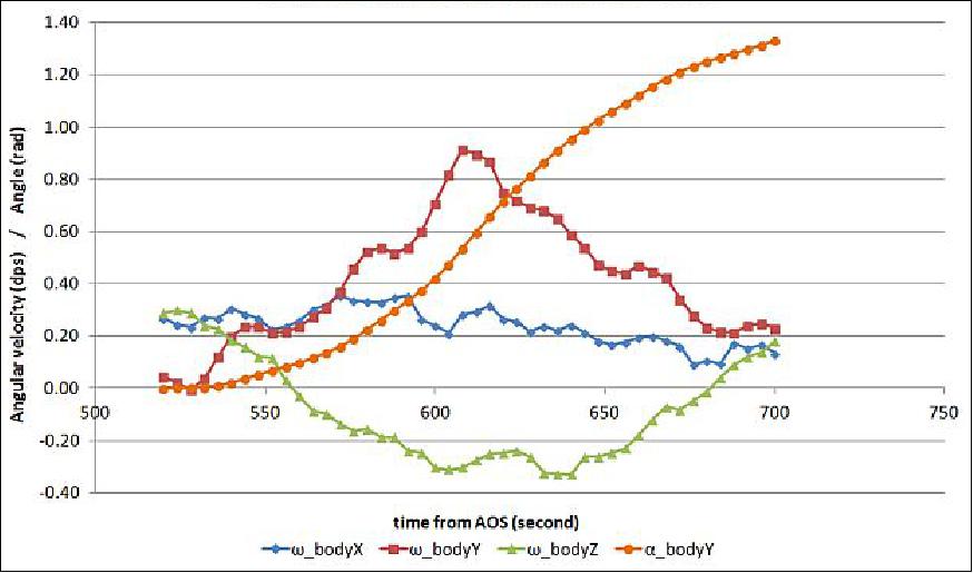
Figures 20 and 21 show another example of bang-bang maneuver that is specifically used to reproduce a target pointing activity, however, only in single axis. In this case, different duty cycles were applied over the period range that the satellite has to keep pointing at a specific target.
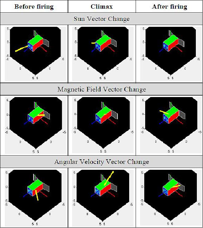
The attitude change of the satellite can also be confirmed with the reading of other attitude sensors, such as magnetometer and sun sensors. Figure 22 shows the vector change of the sun vector, magnetic field, and angular velocity, after the target pointing attempted on the Y axis of the satellite.
Total Mission ΔV
An estimation of the total ΔV actually produced by the micropropulsion system during the 9 months of recorded operation can be attempted based on the impulse achieved on the various maneuvers reported here. For each maneuver, the angular impulse is converted in equivalent linear impulse through the calculation of the force F that produced the Δω around the axis of inertia J in the firing time Δt.
Average specific impulse on experiments | Isp (Specific Impulse) | 31.8 s |
Extrapolation on the Whole Mission | ||
Average specific impulse on mission |
| 43.0 s |
Initial pressure | P0 | 7.8 bar |
Total mass | m0 | 2.39 x 10-02 kg |
Total ΔV based on in-orbit experiments | ΔV | 2.25 m/s |
Total ΔV based on the whole mission | ΔV | 3.05 m/s |
Total ΔV for 1 month mission | ΔV | 5 m/s |
Imager
The secondary payload is a high-resolution catadioptric optical system, a revolutionary design for a CubeSat and confidential at this time. A description will be provided when available.
Mission Status
• In the summer of 2015 (submit of paper to the conference), the payload of the POPSAT-HIP1 3U CubeSat and has been operated in space for 9 months. The performances have been measured to confirm the functionality of the system for maneuvers of up to 4º/s with the tank pressure reduced at 2 bar. For higher supply pressures up to 5 bar, maneuvers of up to 10º/s can be obtained. It is also worth to mention, that such changes of angular velocity or the corresponding satellite rotations are achieved rather quickly, hence allowing re-orientation of the satellite in less than one minute.
- The overall operation has demonstrated a total ΔV of up to 3m/s available during 9 months in orbit, thereby ensuring attitude reorientation on a daily basis for a one year mission or for about 1000 times.
- If higher pressure levels are allowed by the launch provider, the ΔV can be increased between 10 -100 times just by adopting different tank technologies presently available at Engineering Model level at Microspace, thereby increasing the number of maneuvers, being target pointing or formation flight, orbital station keeping, or small orbital changes.
References
1) Giulio Manzoni, Yesie L. Brama, "CubeSat Micropropulsion Characterization in Low Earth Orbit," Proceedings of the 29th Annual AIAA/USU Conference on Small Satellites, Logan, Utah, USA, August 8-13, 2015, paper: SSC15-IV-5, URL: http://digitalcommons.usu.edu/cgi/viewcontent.cgi?article=3190&context=smallsat
2) David Hinkley, "A Novel Cold Gas Propulsion System for Nanosatellites and Picosatellites," Proceedings of the 22nd AIAA/USU conference on Small Satellites, Logan, Utah, USA, Aug. 11-14, 2008, URL: http://digitalcommons.usu.edu/cgi/viewcontent.cgi?article=1393&context=smallsat
3) Giulio Manzoni, Pierpaolo Miotti, Federico De Grandis, Lisa Vaccari, Benedetta Marmiroli, Frederic Perennes, Enzo Di Fabrizio, Paolo Tortora, "Components for Chemical Micropropulsion Systems, an overview on strategies, concepts, studies, prototypes and concrete possibilities," TOS-MPC/2168/ML, 2002, URL: https://escies.org/download/webDocumentFile?id=1097
4) Giulio Manzoni, "Microspace Micropropulsion Roadmapping, Strategy and R&D Achievements," ESA, Noordwijk, 2007, URL: https://escies.org/download/webDocumentFile?id=7179
5) Patrick Blau, "Dnepr Rocket successfully Launches Cluster of 37 Satellites," Spaceflight 101, June 19, 2014, URL: http://www.spaceflight101.com/dnepr-launch-updates---2014-cluster-launch.html
6) William Graham, "Russian Dnepr rocket lofts record haul of 37 satellites," NASA Spaceflight.com, June 19, 2014, URL: http://www.nasaspaceflight.com/2014/06/russian-dnepr-rocket-record-launch-37-satellites/
8) "SSTL announces successful launch of KazEOSat-2," SSTL, June 19, 2014, URL: https://www.sstl.co.uk/media-hub/latest-news/2014/sstl-announces-successful-launch-of-kazeosat-2
9) Patrick Blau, "Dnepr - 2014 Cluster Launch," Spaceflight 101, June 10, 2014, URL: http://www.spaceflight101.com/dnepr-launch-updates---2014-cluster-launch.html
10) Giulio Manzoni, Yesie Lestari Brama, Adam Austin, Rob Conde, "Laboratory Characterization of a Complete Cold Gas Micropropulsion System for Nanosatellite Attitude Control and Formation Flight," Proceedings of the 27th ISTS (International Symposium on Space Technology and Science), Tsukuba, Japan, July 5-12, 2009, URL: http://www.ai-solutions.com/Portals/0/AI%20Docs/Technical%20Paper%20Library%20pdf/2009/10.pdf
11) ISL (ISIS Launch Services), "POPSAT-HIP1 ready for launch," June 3, 2014, URL: http://blog.isilaunch.com/?p=885
The information compiled and edited in this article was provided by Herbert J. Kramer from his documentation of: "Observation of the Earth and Its Environment: Survey of Missions and Sensors" (Springer Verlag) as well as many other sources after the publication of the 4th edition in 2002. - Comments and corrections to this article are always welcome for further updates (eoportal@symbios.space).
Overview Spacecraft Launch Experiment Complement Mission Status References Back to top