ORS-3 Mission / STPSat-3 (Space Test Program Satellite-3)
Non-EO
DoD (USA)
Quick facts
Overview
| Mission type | Non-EO |
| Agency | DoD (USA) |
| Launch date | 20 Nov 2013 |
ORS-3 Mission / STPSat-3 (Space Test Program Satellite-3)
Overview Spacecraft Launch Mission Status Sensor Complement References
The ORS (Operationally Responsive Space) Office, a DoD program conceived to demonstrate space systems on leaner budgets and rapid schedules, is sponsoring the ORS-3 (Operationally Responsive Space) mission, which is planned to launch in 2013 from MARS (Mid-Atlantic Regional Spaceport), located at NASA's Wallops Flight Facility,Wallops Island, VA.
The objectives of the ORS-3 mission are: 1) 2)
1) Demonstrate an AFSS (Autonomous Flight Safety System) which will have the most enduring impact on how flight safety is achieved for all launch systems. The AFSS is the primary goal of the flight testing space-based rocket tracking technology and an autonomous termination system smart enough to destroy the rocket if it flies off course.
The Air Force is migrating toward using GPS receivers on rockets to avoid the overhead costs of legacy radar trackers. The next step will be for launch vehicles to track themselves, comparing real-time GPS positions to predicted values, and issuing a command to destroy itself if it veers too far from its planned flight path. 3) 4) 5)
2) Demonstrate alternative execution methods for launch services that reduces overall launch costs using an FAA license.
3) Demonstrate new hardware that allows small launch vehicle to fly multiple CubeSats in a manner that is benign to the primary mission.
The ORS-3 mission is focused on breaking the constraining paradigms and procedures associated with the acquisition, coordination, range logistics, mission safety, technical management, and overall execution of an existing launch capability. 6)
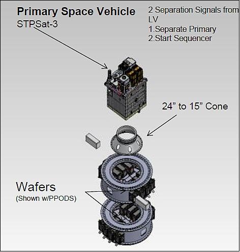
The launch will feature a primary payload, the STPSat-3 (Space Test Program Satellite-3) of the US Air Force SMC (Space and Missile Systems Center), and 27 additional experiments comprised of free-flying systems and non-separating components. ORS-3 will employ CubeSat wafers, which enable secondary payloads to take advantage of excess lift capacity unavailable to the primary trial.
Spacecraft
STPSat-3 is a microsatellite mission of the USAF-SMC. The STPSat series of satellites, built by BATC (Ball Aerospace & Technologies Corporation), successfully proves the concept of a SIV (Standard Interface Vehicle) for the USAF- SMC/SD (Space and Missile Systems Center, Space Development & Test Directorate (SMC/SD).
The STPSat-3 spacecraft is able to support a variety of experimental and risk reduction payloads at different low-Earth orbits and is compatible with multiple launch vehicles by utilizing the flight-proven BCP-100 (Ball Configurable Platform 100) standard interface bus.
The STP-SIV (BCP-100) design supports the goal of a low-risk spacecraft bus by using flight-proven components, a simple structural design, and significant hardware and software reuse from prior missions. The design balances a low-cost and low-risk approach with substantial spacecraft capability and flexibility. 7)
The standard design and payload interface provide mission flexibility, enable operation over a wide range of low Earth orbits, and allow for launch on a variety of launch vehicles. STP-SIV is designed for small payload suites (70 kg total payload mass) and is compatible with the cost-effective ESPA and Minotaur IV MPA, amongst other launch options.
Spacecraft capabilities | |
Orbit altitude range, inclination range | 400 - 850 km, 0º – 98.8º |
Launch mass | ≤180 kg |
Launch vehicle compatibility | Delta IV ESPA, Atlas V ESPA, Minotaur I, Minotaur IV, Pegasus |
Space vehicle lifetime | No life-limiting consumables |
Reliability | Ps = 0.93 @ 1 year; 0.81 @ 3 years; 0.71 @ 5 years |
Stabilization method | 3-axis stabilized |
Pointing modes | Nadir, ground target tracking, inertial point, payload sun point, safe |
Attutude knowledge | 0.02º 3σ |
Attitude control | 0.03º – 0.10º 3σ depending on mode |
Bus voltage | 28 V ± 6 V |
Communication frequency | AFSCN / STDN compatible |
Command rate, telemetry rate | 2 kbit/s uplink, 2 Mbit/s downlink |
Onboard data storage | 16 Gbit |
Payload accommodation | |
Payload mass | 70 kg (total) |
Payload OAP (Orbit Average Power) | >200 W (best case orbit), 100 W (worst case) |
Number of payloads | Nominally four |
Payload data handling | Up to 2.0 Mbit/s from each payload |
Payload command/data interface | RS-422, discrete I/O, analog |
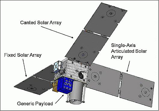
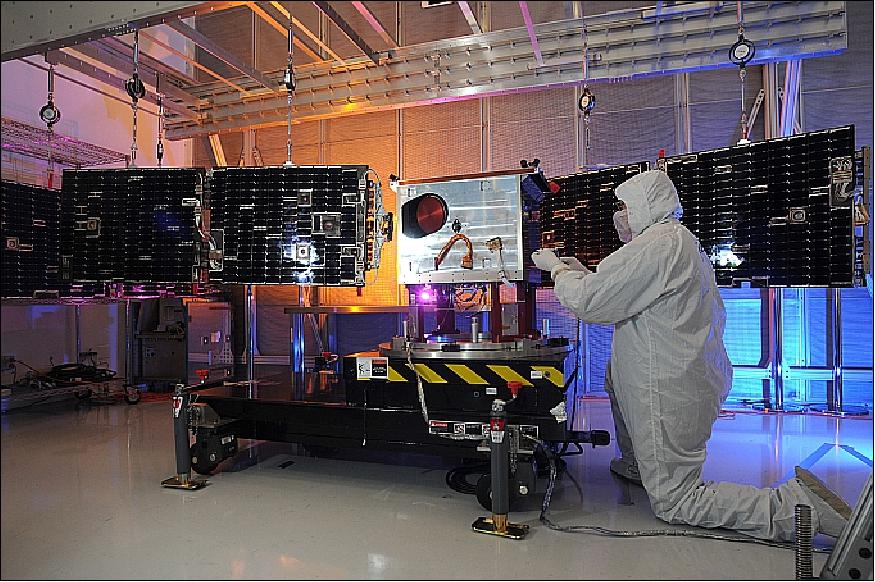
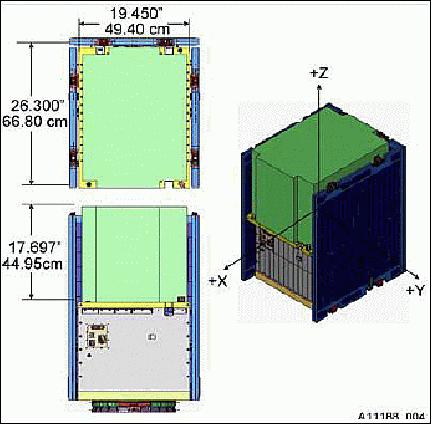
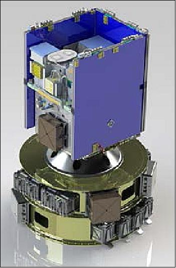
The STP-SIV capabilities support a variety of potential small payloads. To support the range of low Earth orbit altitudes and inclinations, the design shown in Figure 3 includes three separate solar arrays including one articulated wing to provide the required power over a very large range of sun angles. MLI (Multi-Layer Insulation) blankets are mission-tailored to expose appropriate radiator area for the particular orbit and payload suite. A single star tracker is the primary sensor element of the attitude determination and control system. It is mounted directly on the PIP (Payload Interface Plate) to minimize alignment shift between the sensor and payload suite.
By its charter, SMC/SD "develops, tests, and evaluates Air Force space systems, executes advanced space development and demonstration projects, and rapidly transitions capabilities to the warfighter." The STP-SIV design is a natural fit for deployment as a responsive space asset as a consequence of its standardization. STP-SIV (BCP-100) design is flexible and capable of accommodating a broad range of payloads, including those requiring precision pointing performance.
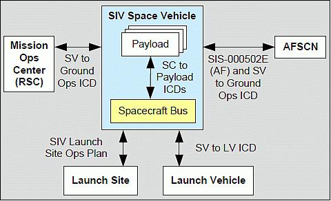
STP-SIV has four external interfaces (Figure 3): payload, launch vehicle, AFSCN (Air Force Satellite Control Network) and the mission ops complex. Interfaces with the launch vehicle are kept simple by design and are intended to be as common as possible for all the potential launch vehicles. The AFSCN and mission operations facility interfaces were developed for STPSat-2, and minimal payload-specific changes were required for STPSat-3. The payload interface is defined and documented in the PLUG, but the specific implementation changes for every mission within the configurable standard.
Spacecraft to Launch Vehicle Interface: STP-SIV is designed to launch on a variety of launch vehicles (LV), including Pegasus, Minotaur I, Minotaur IV, and the ESPA on either Atlas V or Delta IV (compatibility with SpaceX's Falcon 9 and Falcon-Heavy is expected). This flexibility maximizes launch manifest opportunities as a secondary payload or as a rideshare partner and is a key element in satisfying SMC/SD's objective of maximizing its spaceflight opportunities. The spacecraft was designed to be bounded by the environments for the above LVs to ensure generic compatibility. STP-SIV was designed to meet the ESPA volume (Figure 5) as it was the most constraining. Furthermore, STP-SIV is designed to be powered off prior to integration with the LV and requires only safety monitoring of the battery and the ability to trickle charge for periods as long as 90 days. This keeps the number of interfaces required from the LV to a minimum and aids in compatibility with multiple platforms. By designing-in compatibility with a range of candidate LVs and qualifying the design for the maximum enveloping environment, the STP-SIV enables responsive launch to urgent needs. A STP-SIV with a high priority payload could take advantage of a launch of opportunity on any LV or could be manifested quickly on a LV prepared in advance for a responsive launch.
Spacecraft to Payload Interface: In classic space programs, the payload (PL) is developed in advance of or in parallel with the spacecraft (SC) bus, and the SC-PL interface is unique to one program. STP-SIV defines and thoroughly documents a standard PL interface capable of supporting mechanical, electrical, thermal, and data transfer needs common to many small PLs. This interface is controlled by the publicly-available STP-SIV PLUG. 8) By providing a well-defined interface standard, PL providers and responsive space mission designers have sufficient information to proceed in parallel with designs of many PL types for a range of possible missions, knowing the SC bus is already prepared to support them. PLs designed to the standard become effectively interchangeable such that a single STP-SIV bus can be responsive to many missions. No longer must the PL be manifested prior to SC design. In fact, for STPSat-3, the SC components were ordered over three years in advance of the final PL manifest decision (March 2009 vs. May 2012), and bus integration was completed 16 months prior to that decision.
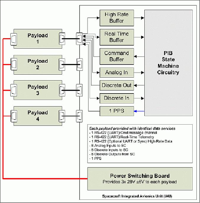
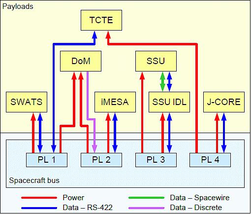
The PIB (Payload Interface Board) within the IAU (Integrated Avionics Unit) functions as the main data and command interface between the PLs and the SC. This includes PL command, data collection, and data storage. Figure 6 shows how the PIB interfaces with the four PLs. Each of the four PLs receives its own set of interfaces on the PIB to ensure operations of each PL do not interfere with the others. All PL data (high rate and real-time) is polled and ingested in a "round robin" scheme ensuring that no PL can monopolize the bus. Both the PL high rate and real-time data are time-stamped at the time of receipt.
The PIB ingests PL high rate mission data at up to 2 Mbit/s via either asynchronous UART EIA-422 link or synchronous EIA compliant RS-422 link. The choice of synchronous or asynchronous data transfer method is selectable for each PL and is fixed prior to launch. The PIB also provides for collection of PL real-time data via EIA-422 UART for health & status monitoring. This data is interleaved into the real-time SC downlink and is also stored on the PIB for retransmit (Ref. 7).
Finally, the PIB provides to each PL data port eight analog inputs, eight discrete inputs, and eight discrete outputs. Analog and discrete telemetry channels are sampled once per second, with 12 bit resolution on analogs.
The PIB provides total mass memory storage of 16 Gbit of EDAC-validated memory space for recording of PL mission data. The memory is partitioned based on PL storage needs.
During nominal mission operations, the SC provides a minimum 100 W OAP (Orbit Average Power) shared among the PLs. Larger PL requirements may require PL duty cycling. Each PL is provided three switched power feeds, allowing flexibility of operations.
The PIP (Payload Interface Plate) PIP is maintained to temperatures between -9° and +39°C with cold biased active heater control configuration. The material selection and sizing of MLI for the PL portion of the SV is customized based on PL power dissipation, field of view requirements, orbital parameters, and concept-of-operations (CONOPS) specific to the mission. Radiator sizing on the SC bus is also adjusted based on these requirements. Survival heaters may be used on PL components to protect hardware in non-operational modes (Ref. 7).
STPSat-3, the second STP-SIV spacecraft was built in only 47 days. Construction of the STPSat-3 platform was completed before the final payloads had been selected, demonstrating the flexibility of the hardware.
On Sept. 6, 2013, the STPSat-3 arrived at Wallops Flight Facility located on Wallops Island, Virginia. 9)
Launch
STPSat-3 was launched on November 20, 2013 (01:15 :00 UTC) from the MARS (Mid-Atlantic Regional Spaceport) on Wallops Island, VA on a Minotaur-1 vehicle of OSC (Orbital Sciences Corporation). The launch was part of the ORS-3 (Operationally Responsive Space-3) enabler launch mission. 10) 11) 12)
ORS-3 is ushering in launch and range processes of the future. The ORS-3 mission will demonstrate and validate a new launch vehicle flight safety architecture of the future through the AFSS (Autonomous Flight Safety System) payload, which uses launch vehicle orbital targeting and range safety planning processes to protect public safety from an errant launch vehicle during flight. 13) The outcome of this test is of great interest to the military as well as to NASA. The launch also will be part of the Federal Aviation Administration's (FAA) certification process for the Minotaur rocket. The FAA has licensing authority over American commercial rockets.
Orbit: Near-circular orbit, altitude = 500 km, inclination = 40.5º.
Secondary Payloads: The secondary technology payloads on this flight consist of 26 experiments comprised of free-flying systems and non-separating components (2 experiments). ORS-3 will employ CubeSat wafer adapters, which enable secondary payloads to take advantage of excess lift capacity unavailable to the primary trial. 14) 15)
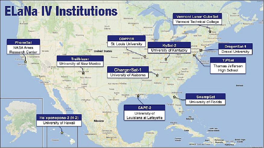
NASA's LSP (Launch Services Program) ELaNa-4 (Educational Launch of Nanosatellite-4) will launch eight more educational CubeSat missions. The ELaNa-4 CubeSats were originally manifest on the Falcon-9 CRS-2 flight. When NASA received word that the P-PODs on CRS-2 needed to be de-manifested, LSP immediately started looking for other opportunities to launch this complement of CubeSats as soon as possible. 16)
Spacecraft | ORS-3 mission sponsor | Spacecraft provider | No of CubeSat Units |
ORS-1, ORSES (ORS Enabler Satellite) | ORS (US Army) | Miltec Corporation, Huntsville, AL | 3 |
ORS-2, ORS Tech 1 | ORS Office | JHU/APL, Laurel, MD | 3 |
ORS-3, ORS Tech 2 | ORS Office | JHU/APL | 3 |
Prometheus-1 | SOCOM (Special Operations Command) | LANL (Los Alamos National Laboratory) | 1 x 3 |
Prometheus-2 | SOCOM | LANL | 1 x 3 |
Prometheus-3 | SOCOM | LANL | 1 x 3 |
Prometheus-4 | SOCOM | LANL | 1 x 3 |
SENSE-A | STP (Space Test Program) | SMC/XR USAF, Boeing Co. | 3 |
SENSE-B | STP | SMC/XR, USAF, Boeing Co. | 3 |
Firefly | NASA/NRO | NSF (National Science Foundation) | 3 |
STARE-B (HORUS) | NRO (National Reconnaissance Office) | Lawrence Livermore National Laboratory | 3 |
Black Knight-1 | NASA LSP/STP | US Military Academy, West Point, NY | 1 |
TetherSat | NASA LSP/STP | US Naval Academy, Annapolis, MD | 3 |
NPS-SCAT | NASA LSP/STP | Naval Postgraduate School, Monterey, CA | 1 |
Ho'ponopono | NASA LSP/STP | University of Hawaii, Manoa, HI | 3 |
COPPER | NASA LSP/STP | St Louis University, St. Louis, MO | 1 |
ChargerSat-1 | NASA LSP/STP | University of Alabama, Huntsville | 1 |
SPA‐1 Trailblazer | NASA LSP/STP | COSMIAC, University of New Mexico | 1 |
Vermont Lunar CubeSat | NASA LSP/STP | Vermont Technical College, Burlington, VT | 1 |
SwampSat | NASA LSP/STP | University of Florida, Gainsville, FL | 1 |
CAPE-2 | NASA LSP/STP | University of Louisiana, Lafayette, LA | 1 |
DragonSat-1 | NASA LSP/STP | Drexel University, Philadelphia, PA | 1 |
KYSat-2 | NASA LSP/STP | Kentucky Space, University of Kentucky | 1 |
PhoneSat-2.4 | NASA LSP/STP | NASA/ARC, Moffett Field, CA | 1 |
TJ3Sat (CubeSat) | NASA LSP/STP | Thomas Jefferson High School, Alexandria, VA | 1 |
ORS and CubeStack: 20)
• ORS (Operationally Responsive Space) partnered with NASA/ARC and AFRL to develop & produce the CubeStack
• Multi CubeSat adapter provides "Low Maintenance" tertiary canisterized ride capability
• ORS-3 Mission: Will fly 2 CubeStacks in November 2013. This represents the largest multi-mission launch using a Minotaur I launch vehicle (26 free flyers, 2 experiments).
The CubeStack adapter structure is a design by LoadPath LLC of Albuquerque, NM, and of Moog CSA Engineering, Mountain View, CA. 21) 22)
The two companies, under contract to the AFRL (Air Force Research Laboratory) Space Vehicles Directorate, developed a multi-payload adapter for CubeSats in support of government and commercial missions. The CubeStack adapter is a 10 inch (25 cm) tall "wafer" similar to the NLAS (NanoSat Launch Adapter System) adapter developed at NASA Ames. The wafer mounts between the rocket upper stage and its primary payload and accommodates eight 3U dispensers, e.g. P-PODs, four 6U CubeSat dispensers, or other combinations of 3U and 6U dispensers. The modular CubeStack wafer features both 98.5 cm Ø and 61 cm Ø primary-spacecraft interfaces and is sized for several launch vehicles including Athena, Minotaur I, Taurus, Pegasus and Falcon 1. 23)
Actually, components from two systems - namely Cubestack (of AFRL) and NLAS (Nanosatellite Launch Adapter System) of NASA/Ames - were used in the successful deployment of the Cubesats from the Nov. 20, 2013 launch on Minotaur-1. From a perspective of NLAS hardware, that launch included: 24)
• 2 NLAS Sequencers and 4 NLAS Dispensers
• The NLAS Sequencers were responsible for commanding the deployment of 28 CubeSats (48U) from 4 NLAS Dispensers and 8 Cal Poly P-PODs.
NASA/Ames developed the NLAS system in coordination with the AFRL's Space Vehicle Directorate. Ames designed and engineered the NLAS system for broad use, and has shared the design data of NLAS with AFRL. - The launch adapters (or CubeStack adapter structures) that were used for this Minotaur-1 mission were procured by the AFRL from LoadPath LLC of Albuquerque, NM, and of Moog CSA Engineering, Mountain View, CA
Mission Status
• According to WMO OSCAR (Observing Systems Capability Analysis and Review Tool), the STPSat-3 mission is operational in 2016. 25)
• April 2015: The STPSat-3 mission is operational in 2015 (Ref. 31).
• Aug. 22, 2014 (status of TCTE): At the time of the TCTE launch on November 20, 2013, the aging SORCE satellite was in a power-saving mode to preserve its extremely limited battery life. Scientists hoped both instruments would work simultaneously in space for at least 10 days to allow scientists on the ground to cross-calibrate the readings from the two nearly identical solar irradiance instruments. In late December 2013, the very important overlap took place when the SORCE computer was able to operate through a period of short eclipses to provide calibration opportunities. 26)
- Not only did the scientists get their wish for 10 days of simultaneous observations, but SORCE is now functioning again due to the programming efforts at LASP.
- In February 2014, the project operations team at LASP reprogrammed the SORCE satellite to quickly power up its computer for all four SORCE instruments during each orbit when there is sunlight on SORCE's solar panels. This resurrected mode is meeting many of the mission's original objectives, albeit ones that are scaled back from the primary mission, and will continue into the foreseeable future.
- In addition to SORCE lasting well beyond its expected lifetime, the TCTE team is benefitting from another advantage. The TIM instrument for the TCTE project was one of several instruments launched aboard the U.S. Air Force Space Test Program Satellite-3 (ORS-3).
- While NOAA only required a single 100 minute observation per week, the Air Force provided an extended calibration period of two observations daily. The TIM on TCTE is currently conducting observations once weekly as originally planned, saving some mission cost while the SORCE instruments continue to function.
• Feb. 20, 2014: The ORS-3 launch vehicle also carried an AFSS (Autonomous Flight Safety System) unit that integrated GPS, an inertial measurement unit and Wallops-developed algorithms to track the rocket's path as it lifted off the gantry and streaked across the horizon. 27)
- Developed by ATK (Alliant Techsystems Inc.) of Plymouth, MN, the shoe box-size unit worked in shadow mode during its first certification test. As part of that test, range officers programmed the unit to respond to a simulated signal indicating that the rocket had gone off course and to send a self-destruct or detonate command at the appropriate time. - Preliminary data indicate that the unit sent the simulated termination command at the right time.
- Initial testing of AFSS began more than three years ago. However, in those flight demonstrations the team used a system cobbled together with commercial, off-the-shelf components married to the Wallops-developed software. The test during the ORS-3 launch, however, employed the actual unit that ATK built under contract.
- As a result of the unit's successful function test, the AFSS team plans to execute another test during a rocket launch of the ORS-4 mission from the PMRF (Pacific Missile Range Facility) in Kauai, Hawaii, in the fall of 2014. Once the team finishes the certification, it believes AFSS will become fully operational in a couple years.
• January 09, 2014: BATC announced it has turned over control of the recently launched STPSat-3 mission to the U.S. Air Force. 28) 29)
• STPSat-3 commissioning began immediately upon satellite acquisition on November 20, 2013. Commissioning included checkout of the SC bus, followed by power-on and verification of PL components. Bus commissioning was completed very quickly, requiring only 72 hours. Furthermore this effort was accomplished with no major anomalies on either the SC or the ground system (Ref. 7).
- The veteran operations team, along with the solid technical performance of the flight hardware, allowed prompt initialization and turn-on of most mission PLs. The J-CORE instrument was powered on during the first ground pass, iMESA-R on day four, TCTE on day five, and SSU on day six. SWATS was powered on three weeks after launch, per schedule. Of particular note, by initializing TCTE very early in commissioning, the instrument was well-characterized in advance of a planned science data overlap with the instrument it was replacing on-orbit.
- The cross-calibration of TCTE with the TIM (Total Irradiance Monitor) flying on the SORCE mission, occurred in mid-December. Between the early turn-on of TCTE on November 24 and the calibration, a discrepancy in the thermal performance of the PL was identified, and the extra time prior to cross-calibration allowed a CONOPS change to be implemented to bring the instrument within spec and ensure that the calibration would be successful.
• The STPSat-3 spacecraft was deployed ~12 minutes after lift-off at an altitude of about 500 km. The Minotaur's upper stage then executed a pre-planned collision avoidance maneuver before starting deployment of 28 CubeSats sponsored by the ORS office, the U.S. Air Force SMC's (Space and Missile Systems Center) Space Test Program, and NASA's Educational Launch of Nanosatellites (ELaNa) program (Ref. 10).
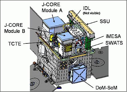
Sensor Complement (iMESA-R, J-CORE, SSU, SWATS, DoM, TCTE)
The final STPSat-3 PL (Payload) manifest consisted of six unique PLs, and the interfaces of those PLs with the SC bus were specified with seven different ICDs. Each of the six PLs had a unique ICD, and the seventh ICD was required for the accommodation of the IDL (Interface Data Logger) box that the SSU PL provided as its data interface to the bus. These seven ICDs contained requirements levied on both the individual PL instrument and the SC bus. The verification process consisted of having the individual PLs demonstrate their compatibility with the bus, as well as having the bus demonstrate its ability to accommodate each unique PL. Given the large number of interfaces resulting from the final PL manifest, it was quite beneficial to have confidence in the bus heritage so that resources could focus on verifying compatibility on the PL side (Ref. 7).
Throughout the design and accommodation process, changes to the SC bus were minimal. Some software modifications were included to account for new requirements of TCTE (Total Solar Irradiance Calibration Transfer Experiment) and DoM/SoM (De-Orbit Module/ Standoff Mechanism). Three temperature sensors were reassigned from the bus to the PLs (two of which were previously spares), and the front bus panel was modified to accommodate the new DoM/SoM option. These minimal bus changes allowed the team to focus on the new PLs and integrate the new PL suite within four months of ATP (Authority To Proceed).
BATC announced in January 2013 that it had successfully integrated the five payloads and a spacecraft de-orbit module onto STPSat-3. 30)
iMESA-R (Integrated Miniaturized Electrostatic Analyzer Reflight)
The instrument is a USAFA (U. S. Air Force Academy) mission designed to measure in-situ plasma densities and energies. The iMESA instrument measures the energy spectrum of the low energy plasma in the ionosphere. From this energy spectrum, we can derive the plasma density, temperature and spacecraft charging of the host spacecraft3. Figure 13 shows an example from the STPSat-3 mission. The energy time spectrum covers 0-40 eV in energy, and approximately 90 minutes (one full orbit) in time. The color scale is the ion current measured by the instrument, and is proportional to the plasma density. In the example shown in Figure 13, the measured current is approximately 4-5 nA. The width of the distribution is proportional to the temperature and the actual energy of the distribution is proportional to the host spacecraft charging. 31)
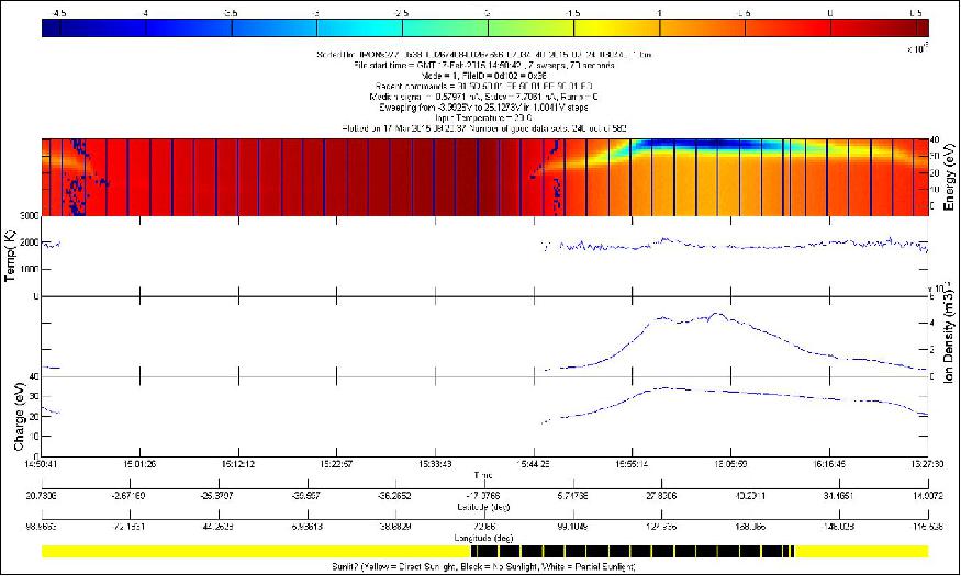
Legend to Figure 13:The top graph is the Energy-Time Spectrogram from which the following three data graphs are derived. The plasma temperature is shown first, followed by the ion Density, followed by the magnitude of the spacecraft charging. All the plots are a function of time during a particular orbit along with the position of the satellite (image credit: USAFA)
J-CORE (Joint Component Research)
J-CORE is a space phenomenology mission sponsored by AFRL (Air Force Research Laboratory ) /EO Countermeasures Technology Branch (RYMW) & SWMDC (Army Space and Missile Defense Command). The objective is to demonstrate multifunction technologies in a relevant mission environment.
SSU (Strip Sensor Unit)
SSU is an AFRL Directed Energy (RD) experiment to provide risk reduction through on-orbit testing and operation of a sensor assembly. The objective is to measure temporal and spatial laser illumination profiles.
SWATS (Small Wind and Temperature Spectrometer)
SWATS is a NRL (Naval Research Laboratory) mission to provide in-situ measurements of the neutral and plasma environment to characterize the Earth's ionosphere and thermosphere. The goal is to provide input to neutral and ionospheric models and in-situ validation points for UV remote sensing missions.
DoM (De-Orbit Module)
DoM/SoM (Standoff Mechanism) is an AFRL/RV experiment. The objective is to demonstrate a lightweight, low cost de-orbit device to meet debris mitigation policy.
TCTE (TSI Calibration Transfer Experiment)
TCTE is a NASA/NOAA mission to collect high accuracy, high precision measurements of Total Solar Irradiance to monitor changes in solar irradiance incident at the top the Earth's atmosphere with TCTE instrument provided by LASP (Laboratory for Atmospheric and Space Physics) at the University of Colorado, originally built as a flight-spare instrument, TIM (Total Solar Irradiance), for the SORCE (Solar Radiation and Climate Experiment) mission.
TCTE is not a substitute for JPSS-FF-1 (Joint Polar Satellite System-Free Flyer- 1) TSIS, since TCTE will not fulfill the Level 1 Climate Data Record for TSI (Total Solar Irradiance) because it is less accurate and is not operated continuously, but it does mitigate a gap until TSIS gets on-orbit. 32) 33) 34)
In order to understand the causes of climate change, TCTE will monitor fluctuations in total solar irradiance. Continuation of solar irradiance measurements will help maintain accuracy in this critical long-term data record by overlapping with existing (SORCE/TIM) and planned future (JPSS/TSIS/TIM) instruments.
TIM measures the total light coming from the Sun at all wavelengths. It will be integrated in the TCTE payload. For TCTE, the spare TIM instrument was modified for NOAA under a NASA contract. TCTE was envisioned to fill the possible measurement gap from SORCE until the next generation of solar sensors can be launched on TSIS-1. Along with the TIM, TSIS-1 will have a next-generation Spectral Irradiance Monitor to measure the spectral distribution of the solar irradiance.
References
1) "ORS -Operationally Responsive Space, The Enabler Mission," ORS-3, Aug. 2012, URL: http://ors.csd.disa.mil/media/ORS-3-final-Aug-2012.pdf
2) "ORS Office organizing three new programs," Air Force Materiel Command, Aug. 30, 2012, URL: http://www.afmc.af.mil/news/story.asp?id=123316172
3) ATK's Autonomous Flight Safety Assembly Makes First Flight," PR Newswire, Nov. 19, 2013, URL: http://www.prnewswire.com/news-releases/atks-autonomous-flight-safety-assembly-makes-first-flight-232603831.html
4) Stephen Clark, "Minotaur rocket booked for space-based range demo," Spaceflight Now, April 4, 2012, URL: http://spaceflightnow.com/news/n1204/04minotaurors3/
5) Edmund Burke, Edwin Rutkowski, "Vehicle Based Independent Tracking System (VBITS): A Small, Modular, Avionics Suite for Responsive Launch Vehicle and Satellite Applications," 6th Responsive Space Conference, April 28–May 1, 2008, Los Angeles, CA, URL: https://web.archive.org/web/20150607213613/http://www.responsivespace.com/Papers/RS6/SESSIONS/SESSION%20III/3006_BURKE/3006P.pdf
6) Thomas M. Davis, Mitchell Elson, Aaron Q. Rogers, "Enablers for Operationally Responsive Space," Proceedings of the 9th IAA Symposium on Small Satellites for Earth Observation, Berlin, Germany, April 8-12, 2013, paper: IAA-B9-1001
7) Kenneth Reese, Alex Martin, David Acton, "STPSat-3: The Benefits of a Multiple-Build, Standard Payload Interface Spacecraft Bus," Proceedings of the AIAA/USU Conference on Small Satellites, Logan, Utah, USA, August 2-7, 2014, paper: SSC14-V-3, URL: http://digitalcommons.usu.edu/cgi/viewcontent.cgi?article=3045&context=smallsat
8) "Space Test Program-Standard Interface Vehicle (STP-SIV) Payload Users Guide", Revision D, May 2013
9) "STPSat-3 Built by Ball Aerospace Arrives at Wallops Flight Facility in Virginia," BATC News Release, URL: http://www.ballaerospace.com/page.jsp?page=30&id=542
10) "Orbital Successfully Launches Minotaur I Rocket Supporting ORS-3 Mission for the U.S. Air Force," Orbital, Nov. 19, 2013, URL: http://www.orbital.com/NewsInfo/release.asp?prid=1876
11) Patrick Blau, "Minotaur I successfully launches STPSat-3 & record load of 28 CubeSats," Spaceflight 101, Nov. 20, 2013, URL: http://www.spaceflight101.com/minotaur-i-ors-3-launch-updates.html
12) Roz Brown, "Ball Aerospace's STPSat-3 to Fly Solar TIM Instrument for NOAA," BATC, July 19, 2012, URL: http://www.ballaerospace.com/page.jsp?page=30&id=478
13) Michael P. Kleiman, "ORS Office organizing three new programs," AFMC (Air Force Materiel Command), Aug. 30, 2012, URL: http://www.afmc.af.mil/news/story.asp?id=123316172
14) Peter Wegner, "ORS Program Status," Reinventing Space Conference, El Segundo, CA, USA, May 7-10, 2012, URL: https://web.archive.org/web/20150423114038/http://www.responsivespace.com/Papers/RS2012/SPECIAL%20SPEAKERS/Dr.%20Peter%20Wegner/Dr.%20Peter%20Wegner.pdf
15) Joe Maly, "ESPA CubeSat Accommodations and Qualification of 6U Mount (SUM)," 10th Annual CubeSat Developer's Workshop, Cal Poly State University, San Luis Obispo, CA, USA, April 24-25, 2013, URL: http://www.cubesat.org/images/stories/workshop_media/DevelopersWorkshop-2013/-Maly-MoogCSA_ESPA-SUM.pdf
16) Garrett Lee Skrobot, Roland Coelho, "ELaNa – Educational Launch of Nanosatellite Providing Routine RideShare Opportunities," Proceedings of the 26th Annual AIAA/USU Conference on Small Satellites, Logan, Utah, USA, August 13-16, 2012, paper: SSC12-V-5
17) "NASA Helps Launch Student-Built Satellites and latest PhoneSat as Part of CubeSat Launch Initiative," NASA, Nov. 18, 2013, URL: http://www.nasa.gov/content/nasa-helps-launch-student-built-satellites-and-latest-phonesat-as-part-of-cubesat-launch/#.UphFWSeFcyW
18) "CubeSat ELaNa IV Launch on ORS-3," NASA fact sheet, Nov. 2013, URL: http://www.nasa.gov/sites/default/files/files/ELaNa-IV-Factsheet-508.pdf
19) Joshua Buck, "NASA Helps Launch Student-Built Satellites as Part of CubeSat Launch Initiative," NASA, Release 13-343, Nov. 20, 2013, URL: http://www.nasa.gov/press/2013/november/nasa-helps-launch-student-built-satellites-as-part-of-cubesat-launch-initiative/#.UqASMieFf_o
20) "CubeStack: CubeSat Space Access," 9th Annual Spring CubeSat Developers' Workshop, Cal Poly State University, San Luis Obispo, CA, USA, April 18-20, 2012, URL: http://mstl.atl.calpoly.edu/~workshop/archive/2012/Spring/27-Maly-CubeStack.pdf
21) Joe Maly, "6U Mount for CubeSats on ESPA," CubeSat 9th Annual Summer Workshop, Logan UT, USA, August 11-12, 2012, URL: https://web.archive.org/web/20160914101344/http://mstl.atl.calpoly.edu/~bklofas/Presentations/SummerWorkshop2012/Maly_6U_ESPA_Mount.pdf
22) "CubeStack: CubeSat Space Access," 9th Annual CubeSat Developers' Workshop, Cal Poly, San Luis Obispo, 19 April 2012, URL: http://mstl.atl.calpoly.edu/~workshop/archive/2012/Spring/27-Maly-CubeStack.pdf
23) Gregory E Sanford, Kenneth J Brunetto, Joseph R Maly, James C Goodding, Hans-Peter Dumm, "CubeStack Wafer Adapter for CubeSats on Small Launch Vehicles," Proceedings of the 25th Annual AIAA/USU Conference on Small Satellites, Logan, UT, USA, Aug. 8-11, 2011, paper: SSC11-II-7, URL: http://digitalcommons.usu.edu/cgi/viewcontent.cgi?article=1115&context=smallsat
24) Information provided by Joshua M. Buck of NASA/HQ, Washington D.C.
25) http://www.wmo-sat.info/oscar/satellites/view/541
26) "Spare Off-the-Shelf Instrument Continues Solar Output Data with Excellent Results," Space Daily, Aug. 22, 2014, URL: http://www.spacedaily.com/reports/Spare_Off_the_Shelf_Instrument_Continues_Solar-Output_Data_with_Excellent_Results_999.html
27) Lori Keesey, "'Mission of Firsts' Showcased New Range-Safety Technology at NASA Wallops,"NASA News, Feb. 20, 2014, URL: http://www.nasa.gov/content/goddard/mission-of-firsts-showcased-new-range-safety-technology-at-nasa-wallops/#.Uw24Q87ihqM
28) Mike Gruss, "U.S. Air Force Takes Control of STPSat-3," Space News, Jan. 09, 2014, URL: http://www.spacenews.com/article/military-space/39008us-air-force-takes-control-of-stpsat-3
29) Doug Messier, "Ball Aerospace Turns Over Test Satellite Operations to Air Force," Parabolic Arc, Jan. 13, 2014, URL: http://www.parabolicarc.com/2014/01/13/ball-aerospace-turns-test-satellite-operations-air-force/
30) "Ball Aerospace Integrates Final Payload for STPSat-3," BATC News Releases, Jan. 18, 2013, URL: http://www.ballaerospace.com/page.jsp?page=30&id=513
31) Parris Neal, Alex Strom, Nikolas Taormina, "IMESA-R Integrated Miniaturized Electrostatic Analyzer – Reflight," 31st Space Symposium, Colorado Springs, CO, USA, April 13-16, 2015, URL of paper: http://www.spacesymposium.org/sites/default/files/downloads/P.Neal_31st_Space-Symposium_Tech_Track_paper.pdf, URL of presentation: http://www.spacesymposium.org/sites/default/files/downloads/P.Neal_31st_Space-Symposium_Tech_Track_Presentation.pdf
32) Preston M. Burch, "TCTE / STP3-Sat Mission," July 31, 2012, URL: http://www.goddard-contractors-association.org/presentations/7-31-2012%20GCA%20Presentation%20Preston%20Burch.pdf
33) "Solar instrument bridges gap left by Glory's demise," LASP Press Release, July 18, 2012, URL: http://lasp.colorado.edu/home/blog/2012/07/18/press-release-solar-instrument-bridges-gap-left-by-glorys-demise/
34) "Quick Facts: Total Solar Irradiance Calibration Transfer Experiment (TCTE)," LASP, 2013, URL: http://lasp.colorado.edu/home/about/quick-facts-tcte/
The information compiled and edited in this article was provided by Herbert J. Kramer from his documentation of: "Observation of the Earth and Its Environment: Survey of Missions and Sensors" (Springer Verlag) as well as many other sources after the publication of the 4th edition in 2002. - Comments and corrections to this article are always welcome for further updates (eoportal@symbios.space).
Overview Spacecraft Launch Mission Status Sensor Complement References Back to Top