OrbView-3 Minisatellite
EO
Mission complete
High resolution optical imagers
GeoEye
Launched in June 2003, OrbView-3 was a commercial high-resolution imaging minisatellite developed by Orbital Imaging Corporation (ORBIMAGE) of Dulles, Virginia, USA. In 2006, ORBIMAGE merged with Space Imaging of Thornton, Colorado USA, to establish the commercial imaging company GeoEye. The spacecraft was built with a five-year design life, however, the mission was terminated in April 2007 after an instrument camera malfunctioned, and OrbView-3 reentered Earth’s atmosphere in March 2011.
Quick facts
Overview
| Mission type | EO |
| Agency | GeoEye |
| Mission status | Mission complete |
| Launch date | 26 Jun 2003 |
| End of life date | 23 Apr 2007 |
| Instruments | OHRIS |
| Instrument type | High resolution optical imagers |
| CEOS EO Handbook | See OrbView-3 Minisatellite summary |
Summary
Mission Capabilities
OrbView-3 carried the OrbView High Resolution Imaging System (OHRIS) onboard, developed by Northrop Grumman. Its objective was to provide global high-resolution imagery on a commercial basis.
Performance Specifications
OHRIS was a whiskbroom imager based on a three-mirror anastigmatic telescope design that provided imagery in one panchromatic (PAN) band and four multispectral (MS) bands (blue, green, red and near-infrared (NIR)). It was capable of imaging a swath width of 8 km with a spatial resolution of 1 m for PAN imagery and 4 m for MS imagery. Exposure control was provided by 16 PAN imaging modes, where the camera was commanded to image at a line rate of 5000, 2500, 1000 or 500 lines per second (lps).
OrbView-3 underwent a circular sun-synchronous orbit at an altitude of 470 km and an inclination of 97.25°. It had a period of 92.5 minutes with an equator crossing at 1030 hours on a descending node and a revisit capability of three days, depending on its latitude.
Space and Hardware Components
Built with an original design life of five years, OrbView-3 employed the flight-proven OSC (Orbital Sciences Corporation) LeoStar design with a bus design of STEP (Space Technology Experiment Program) series heritage. The bus consisted of a 12-sided horizontal honeycomb equipment deck with aluminium plate side panels divided into three modules (propulsion, core and payload). The body was a cylinder of 1.2 m in diameter and 1.9 m in length, with a solar panel mounted to the top side of the cylinder. Built with a mass of 360 kg, OrbView-3 was three-axis stabilised with a capability to perform body-pointing of 50° to -50° in the in-track and cross-track directions. The Attitude Control Subsystem (ACS) employed a gyroscope, star sensors, sun sensors and a magnetometer for attitude sensing and four reaction wheels and thrusters for all actuation functions.
In March 2007, OHRIS malfunctioned without warning and despite multiple attempts to restore the system none were successful and the satellite’s operations were terminated in April 2007.
OrbView-3
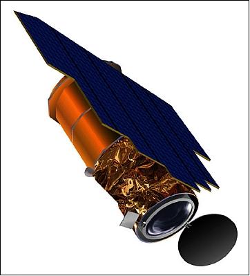
OrbView-3 is a high-resolution imaging minisatellite owned and operated by Orbital Imaging Corporation (ORBIMAGE) of Dulles, VA, a commercial provider of Earth imagery acquired from a family of imaging satellites that it owns and operates. The S/C includes one imaging camera, the OrbView High Resolution Imaging System capable of collecting one meter resolution panchromatic and four meter resolution multispectral imagery.
Note: In January 2006, the commercial imaging company GeoEye was established, made up of the former Orbimage of Dulles VA, and of Space Imaging of Thornton, CO. Orbimage acquired Space Imaging in 2005 and gave the merged company the new name of GeoEye. The new company has HQs in Dulles, VA. 1) 2)

Spacecraft
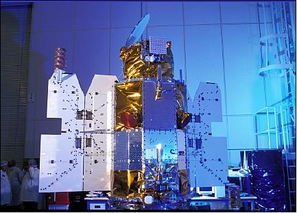
The spacecraft of the OrbView-3 mission uses the flight-proven OSC LeoStar design. The bus design is of STEP (Space Technology Experiment Program) series heritage (USAF, 1991) consisting of 12-sided horizontal honeycomb equipment decks and aluminum plate or honeycomb side panels that stiffen the structure and provide additional radiation protection for the equipment mounted inside. The bus structure is divided into three modules (propulsion, core and payload), each of which is constructed so components can easily be attached to each other for final assembly and checkout.
The S/C body is a cylinder of about 1.2 m in diameter and 1.9 m in length. A solar panel is mounted to the “top side” of the cylinder. OrbView-3 is three-axis stabilized providing a real-time pointing accuracy of < 100 arcseconds (knowledge). The post-processed pointing accuracy allows pixels to be located to within ±12 m for certain product types.
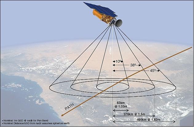
The ACS (Attitude Control Subsystem) employs Orbital-built gyroscope, star sensors, sun sensors, and a magnetometer for attitude sensing, and four reaction wheels (3 always active, one is a cold spare) and thrusters for all actuation functions. The S/C has the capability to perform body-pointing of ±50º into the in-track and cross-track directions thereby increasing the FOR (Field of Regard) for all observations.
The spacecraft bus mass is about 304 kg (launch mass of 360 kg), the spacecraft design life is five years. 3) 4) 5) 6)
Launch
OrbView-3 was launched successfully June 26, 2003 on an OSC launch vehicle (Pegasus-XL) from VAFB, CA, USA.
Orbit: Circular sun-synchronous orbit, altitude = 470 km, inclination = 97.25º, period = 92.5 min, equator crossing at 10:30 hours on a descending node. The revisit capability is 3 days (depending on latitude).
RF communications: On-board storage capability of 32 Gbit (the onboard storage is available for customers requiring imagery of regions where receiving stations are unavailable). Real-time downlink of imagery in X-band at 150 Mbit/s (max, gimballed X-band downlink antenna). UHF-band for TT&C operations.
Mission Status
• OrbView-3 reentry on March 13, 2011: In Nov. 2010, OrbView-3 was in a decayed orbit of ~435 km altitude with a remaining useable propellant of 22.98 kg. Although Orbview-3 would have naturally fallen back to Earth well within the recommended 25-year period, GeoEye followed U.S. government recommendations for the responsible disposal of satellites in LEO — to execute a controlled reentry to immediately eliminate any potential risk of collision to other resident space objects. 7) 8)
Four maneuvers first lowered the orbit of Orbview-3 below that of the International Space Station. Then, four additional maneuvers sent the spacecraft to a carefully orchestrated reentry over the Pacific Ocean on March 13, 2011. 9)
• The OrbView-3 spacecraft and its payload were operating nominally until March 2007 - when a malfunction occurred stopping the imager operations. On April 23, 2007, GeoEye announced that the OrbView-3 mission was terminated. Though GeoEye remained in control of the satellite, it no longer produced usable imagery.
• On March 4, 2007, the imager OHRIS malfunctioned without a warning. Attempts were being made to restore the observation service. The problem was identified to a specific unit within the camera electronics. On March 20, 2007, GeoEye announced that the probability of restoring the camera to normal operations was low. Although a number of steps to attempt to fix OrbView-3 system were identified by the team, none of the efforts to revive the satellite were successful. The OHRIS camera design does not include a redundant set of electronics that would allow to restore operations 10)
Fortunately, the camera was insured. In a regulatory filing with the SEC dated March 8. 2007, GeoEye officials said that the OrbView-3 satellite is suffering from problems with the electronics on its camera that have prevented it from taking usable imagery since March 4. The filing said there was not yet enough information to determine what, if anything, can be done to restore the instrument, nor how long the process will take. 11)
• GeoEye management declared its stricken OrbView-3 satellite to be a total loss in an April 23, 2007 filing with the US SEC (Securities and Exchange Commission). Hence, an operational service life of a bit more than 3 1/2 years was provided - the spacecraft design life was 5 years. 12)


Sensor Complement
OHRIS (OrbView High Resolution Imaging System)
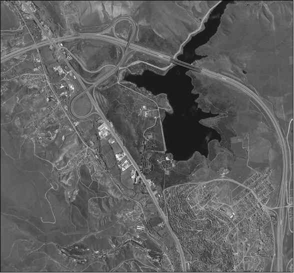
OHRIS of ORBIMAGE is designed and built by Northrop Grumman, Baltimore, MD. The objective is to provide global high-resolution imagery (1 m panchromatic and 4 m multispectral) on a commercial basis. OHRIS is identical to the instrument flown on OrbView-4. OHRIS is an optomechanical instrument (whiskbroom imager) based on a three-mirror anastigmatic (TMA) telescope design with an aperture diameter of 45 cm. The nominal scene size of the imagery is 8 km x 8 km (the swath width is 8 km) with a spatial resolution of 1 m (Pan) and 4 m (MS) at nadir. The source data is generated with 11-bit quantization and compressed to 2 bits/pixel. The instrument mass is 66 kg.
Exposure control is provided by 16 panchromatic imaging modes. The camera may be commanded to image at line rates of 5000 lines per second (lps), 2500 lps, 1000 lps or 500 lps. Additionally, the integration fraction or duty cycle for each line rate may be selected from full, one half, one quarter or one eighth of a sample period. These modes provide broad control over dynamic range, signal to noise ratio and detector smear. For OHRIS imagery the overall Nyquist MTF was measured as 0.10 ± 0.01 (without sharpening). With the nominal sharpening applied to the imagery, the overall NTF (Nyquist Transfer Function) was measured as 0.15 ± 0.01. 13)
Instrument type | Body-scanning whiskbroom imager (in PAN and MS) | |
Imaging Mode | Panchromatic | Multispectral (MS) |
Spatial resolution | 1 m | 4 m |
Imaging bands | 1 | 4 MS |
Spectral range | Pan: 450 - 900 nm | MS1: 450-520 nm (blue) |
Silicon detector size (linear array) | 8000 pixels | 2000 x 4 |
Pixel size of detectors | 6.0 µm x 5.4 µm (cross x along) |
|
Swath width | 8 km | |
Data quantization of imagery | 11 bit (compressed in downlink to 2 bit/pixel) | |
OHRIS calibration: On-orbit geometric calibration is based on the mathematical modelling and estimation of calibration parameters incorporated into a rigorous and flexible self-calibration triangulation, Kalman filter software suite and orbit determination software. The principal components of the geometric model are: orbit determination, attitude determination and camera model. The satellite orbit determination is based on the GIPSY-OASIS (GPS-Inferred Positioning SYstem and Orbit Analysis SImulation Software) package of JPL (Jet Propulsion Laboratory), Pasadena, CA. 14) 15) 16) 17) 18)
Ground Segment
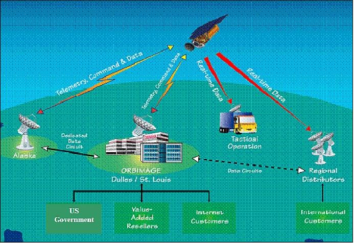
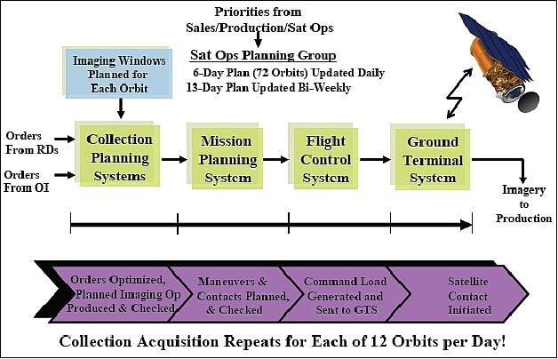
The ORBIMAGE Operations Center (OOC) is located in Dulles, VA providing full-time service. The OOC generates the satellite tasking commands, which are uplinked to the OrbView satellites from two ground stations; one located in Point Barrow, Alaska and the other in Dulles, Virginia. These same ground stations receive and route the telemetry and imagery data downlinked from the satellite back to the OOC for processing and distribution. The imagery data routed to the OOC is processed, archived, and distributed to customers. In parallel, ORBIMAGE franchises these service tasks (data reception, archiving, product generation, distribution, requests for regional image acquisition scheduling, etc.) out to official regional distributors or to large-volume customers. 19)
ORBIMAGE offers several license options for its distributors and large-volume users with regard to their satellite tasking capabilities and priorities in their respective regions of coverage.
References
1) Matthew O'Connell, “GeoEye Overview - GIS Capabilities for Civil Government Agencies,” 2006, URL: http://www.space.commerce.gov/library/workshops/2006-10-19/oconnell.ppt
2) “GeoEye Corporate Overview,” Feb. 24, 2006, URL: http://calval.cr.usgs.gov/JACIE_files/JACIE06/Files/18Jones.pdf
3) Information provided by Mark Pastrone of ORBIMAGE
4) “OrbView-3 Fact Sheet,“ URL: http://www.orbital.com/NewsInfo/Publications/OV3_Fact.pdf
5) http://www.orbital.com/SatellitesSpace/ImagingDefense/OV3/index.shtml
6) Gary G. Adkins, “ORBIMAGE Overview, Turning Imagery into Intelligence,” Proceedings of JACIE (Joint Agency Commercial Imagery Evaluation) High Spatial Resolution Commercial Imagery Workshop, Reston, VA, USA, Nov. 8-10, 2004, URL: http://calval.cr.usgs.gov/JACIE_files/JACIE04/files/1Adkins7.pdf
7) N. Johnson, “USA Space Debris Environment, Operations, and Policy Updates,” Proceedings of the 49th Session of UNCOPUOS-STSC (UN Committee on the Peaceful Uses of Outer Space-Scientific and Technical Subcommittee), Vienna, Austria, Feb. 6-17, 2012, URL: http://www.oosa.unvienna.org/pdf/pres/stsc2012/tech-26E.pdf
8) Bill Schuster, “OrbView¿3 De¿Orbit,” URL: http://licensing.fcc.gov/myibfs/download.do?attachment_key=854478
9) “U.S. Commercial Earth Observation Spacecraft Executes Controlled Reentry,” Orbital Debris Quarterly News, NASA, Vol. 15, Issue 2, April 2011, URL: http://orbitaldebris.jsc.nasa.gov/newsletter/pdfs/ODQNv15i2.pdf
10) C. Parks, “Hope Fades for Recovery of GeoEye's OrbView-3 Satellite,” Space News, March 26, 2007, p. 4
11) “OrbView 3 satellite malfunctions,” Nov. 1, 2010, URL: http://www.spacetoday.net/Summary/3691
12) “GeoEye Formally Abandons OrbView-3 Recovery Effort,” Space News, April 30, 2007, p. 8
13) K. Kohm, “ Modulation Transfer Function Measurement Method and Results from the OrbView-3 High Resolution Imaging Satellite,” Proceedings of ISPRS 2004, Istanbul, Turkey, July 12-23, 2004
14) David Mulawa, “On-Orbit Geometric Calibration of the OrbView-3 High Resolution Imaging Satellite,” Proceedings of ISPRS 2004, Istanbul, Turkey, July 12-23, 2004, URL: http://www.isprs.org/proceedings/XXXV/congress/comm1/papers/1.pdf
15) David Mulawa, “OrbView-3 Geometric Calibration and Geospatial Accuracy,” Proceedings of JACIE (Joint Agency Commercial Imagery Evaluation) High Spatial Resolution Commercial Imagery Workshop, Reston, VA, USA, Nov. 8-10, 2004, URL: http://calval.cr.usgs.gov/wordpress/wp-content/uploads/JACIE_files/JACIE04/files/1Mulaw15.pdf
16) Paul Bresnahan, “Geopositional Accuracy Evaluations of QuickBird and OrbView-3,” Proceedings of JACIE (Joint Agency Commercial Imagery Evaluation) High Spatial Resolution Commercial Imagery Workshop, Reston, VA, USA, Nov. 8-10, 2004, URL: http://calval.cr.usgs.gov/wordpress/wp-content/uploads/JACIE_files/JACIE04/files/2Bresna1.pdf
17) Paul C.Bresnahan, “Geopositional Accuracy Evaluations of OrbView-3, EROS-A, and SPOT-5 Imagery,” Proceedings of the JACIE Workshop, Laurel, MD, USA, March 14-16, 2006, URL: http://calval.cr.usgs.gov/wordpress/wp-content/uploads/JACIE_files/JACIE06/Files/22Bresna.pdf
18) Kara Holekamp, “Radiometric Characterization of the IKONOS, QuickBird, and OrbView-3 Sensors,” Proceedings of the JACIE Workshop, Laurel, MD, USA, March 14-16, 2006, URL: http://calval.cr.usgs.gov/wordpress/wp-content/uploads/JACIE_files/JACIE06/Files/25cHolek.pdf
19) “OrbView-3 Commercial Satellite Imagery Product Catalog,” GeoEye, Jan. 23, 2006, URL: http://glcf.umiacs.umd.edu/library/guide/Orbview3_Product_Guide_25jan06.pdf
The information compiled and edited in this article was provided by Herbert J. Kramer from his documentation of: ”Observation of the Earth and Its Environment: Survey of Missions and Sensors” (Springer Verlag) as well as many other sources after the publication of the 4th edition in 2002. - Comments and corrections to this article are always welcome for further updates (eoportal@symbios.space).