OPUSat (Osaka Prefecture University Satellite)
Non-EO
JAXA
Quick facts
Overview
| Mission type | Non-EO |
| Agency | JAXA |
| Launch date | 27 Feb 2014 |
OPUSat (Osaka Prefecture University Satellite)
OPUSat is a 1U CubeSat educational project developed and designed by students and faculty of SSSRC (Small Spacecraft Systems Research Center) at Osaka Prefecture University (OPU), Osaka, Japan. The overall objectives of the OPUSat mission are: 1)
1) To demonstrate a hybrid power supply system using a LIC (Lithium-ion Capacitor) device and a Li-ion battery in the space environment
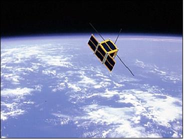
2) To demonstrate deployable solar paddles
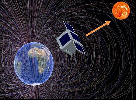
3) To realize sun-pointing active attitude control using magnetic torquers.
Spacecraft
OPUSat conforms to the 1U CubeSat standard with a side length of 10 cm and a mass of 1.2 kg: The structure features deployable solar paddles to boost power generation and a deployable antenna. A block diagram of OPUSat is shown in Figure 2.
ADCS (Attitude Determination and Control Subsystem): The spacecraft is spin stabilized and sun-pointing. The ADCS uses 4 sun sensors, 3 gyroscopes and a magnetometer for attitude sensing and 2 MTQs (Magnetic Torquers) for activation. The ACU (ADCS Control Unit) is used for the attitude control mission. In addition, the MOBC (Mission On-Board Computer) is used for course attitude control.
EPS (Electrical Power Subsystem): The EPS provides power for all devices of the spacecraft using two deployable paddles for an improved power budget. EPS consists of four units: PGU (Power Generation Unit), PCU (Power Control Unit), PSU (Power Storage Unit), and PDU (Power Distribution Unit). The PSU features a Li-ion battery and a LICC (Lithium-Ion Capacitor Controller). The LIC device is used to assist in decreasing the load of the Li-ion battery. The EPS is configured for MPPT (Maximum Power Point Tracking).
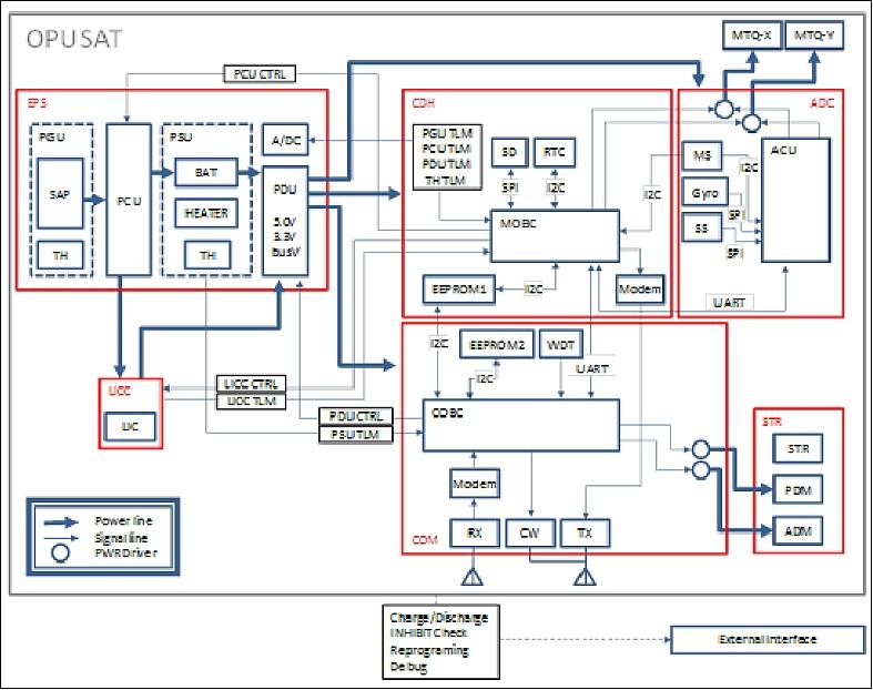
C&DH (Command and Data Handling Subsystem): The C&DH subsystem is comprised of three microprocessors, COBC, MOBC and ACU. The COBC deals with communication between the satellite and a ground station. The MOBC is the main computer of OPUSAT, it deals with command and telemetry and gathers housekeeping log data and mission data. The ACU is a computer for the support of attitude control services. The interfaces between the MOBC and other two computers are UART (Universal Asynchronous Receiver/Transmitter) devices. The COBC is the master microprocessor in the configuration capable to reset the MOBC and the ACU. The COBC features an external WDT (Watch Dog Timer). WDT is a device that will reset COBC after a specified amount of time if the WDT does not receive a signal from the COBC.
TCS (Thermal Control Subsystem): The TCS provides appropriate thermal protection to the payload sensors, circuitry, and batteries in the space environment. The TCS has a heater for LIB and a thermistor (TH).
COM (RF Communications Subsystem): The amateur bands VHF (144 MHz) for uplink and UHF (437.150 MHz) for downlink data transmission are used for telecommunication. COM features a CW beacon, a VHF receiver with AFSK modulation and 1200 bit data rate, and a UHF transmitter with GMSK modulation and a data rate of 9.6 kbit/s. 2)
Launch
The OPUSat CubeSat was launched as a secondary payload on the H-IIA 202 vehicle of JAXA on February 27, 2014 (18:37:00 UTC). The primary payload on this flight was the GPM (Global Precipitation Measurement) mission of NASA and JAXA. The launch site was the Tanegashima Space Center, Japan. 4)
Secondary Payloads on the GPM Core Mission (Japanese/ Manifested by JAXA ) 5)
• ShindaiSat (Shinshu University Satellite), also known as Ginrei, is a microsatellite (35 kg) to demonstrate LED light as an optical communications link.
• STARS-2 (Space Tethered Autonomous Robotic Satellite-2) nanosatellite technology mission of Kagawa University, Takamatsu, Kagawa, Japan
• TeikyoSat-3, a bioscience microsatellite (~20 kg) of Teikyo University
• ITF-1 (Imagine The Future-1), a 1U CubeSat of the University of Tsukuba, Tsukuba, Japan.
• OPUSat (Osaka Prefecture University Satellite), a 1U CubeSat
• INVADER (INteractiVe satellite for Art and Design Experimental Research) of Tama Art University, a 1U CubeSat
• KSat-2 (Kagoshima University Satellite-2), a CubeSat mission with a mass of ~ 1.5 kg. 6)
Orbit Non-sun-synchronous circular orbit, altitude = 407 km, inclination = 65º.
After the release of the GPM Core Satellite, the second stage performed attitude maneuvers and slightly changed its orbit for the deployment of the seven secondary payloads that include small spacecraft and CubeSats dedicated to scientific missions, technical demonstrations and outreach projects. 7)
Launch event | Time (minutes:seconds) | Altitude (km) | Inertial speed (km/s) |
Liftoff | 0:00 | 0 | 0.4 |
Solid rocket booster burnout | 1:39 | 47 | 1.5 |
Solid rocket booster jettison (thrust strut cutoff) | 1:48 | 55 | 1.5 |
Payload fairing jettison | 4:05 | 140 | 2.5 |
1st stage engine (main engine) cutoff (MECO) | 6:36 | 230 | 5.0 |
1st and 2nd stages separation | 6:44 | 236 | 5.0 |
2nd stage ignition (SEIG) | 6:50 | 239 | 5.0 |
2nd stage engine cutoff (SECO) | 14:58 | 399 | 7.7 |
GPM-Core separation | 15:49 | 398 | 7.7 |
ShindaiSat cubesat separation | 24:09 | 400 | 7.7 |
STARS-2 CubeSat separation | 28:19 | 403 | 7.7 |
TeikyoSat-3 microsatellite separation | 32:29 | 406 | 7.7 |
ITF-1 CubeSat separation | 36:39 | 408 | 7.7 |
OPUSAT CubeSat separation | 37:59 | 408 | 7.7 |
INVADER CubeSat separation | 39:19 | 408 | 7.7 |
KSat-2 CubeSat separation | 40:39 | 408 | 7.7 |
Sensor Complement (LIC)
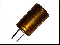
LIC (Lithium-Ion Capacitor)
LIC is a large capacity device and is superior to conventional chemical batteries in life cycle duration, with a high energy density (reportedly 14 Wh/kg), as well as in low temperature characteristics. The objective is to demonstrate a hybrid power supply configuration using LIC and Li-ion battery techniques by utilizing high power density which is a characteristic of LIC. The goal is to assist in decreasing the load of Li-ion battery.
References
1) Atsushi Nishino, Yohsuke Nambu, Takashi Bessho, Hiroshi Okubo, “Practical Development Process for Nano Satellite Based on Experience of Developing OPUSAT,” Proceedings of the 29th ISTS (International Symposium on Space Technology and Science), Nagoya-Aichi, Japan, June 2-8, 2013, paper: 2013-f-02
2) “OPUSat,” IARU (International Amateur Radio Union) Amateur Satellite Frequency Coordination, May 22, 2013, URL: http://www.amsatuk.me.uk/iaru/formal_detail.php?serialnum=307
3) “OPUSAT Bound for Space,” OPU, Feb. 15, 2012, URL: https://web.archive.org/web/20151121110242/http://www.osakafu-u.ac.jp/english/info/overview/spotlight/2011/h24_0215.html
4) “Launch Result of H-IIA Launch Vehicle No. 23 with GPM Core Observatory onboard,” MHI, JAXA, Feb. 28, 2014, URL: http://www.jaxa.jp/press/2014/02/20140228_h2af23_e.html#ref
5) Toshinori Kuwahara, Kazaya Yoshida, Yuji Sakamoto, Yoshihiro Tomioka, Kazifumi Fukuda, Nobuo Sugimura, Junichi Kurihara, Yukihoro Takahashi, “Space Plug and Play Compatible Earth Observation Payload Instruments,” Proceedings of the 9th IAA Symposium on Small Satellites for Earth Observation, Berlin, Germany, April 8-12, 2013, Paper: IAA-B9-1502, URL: http://media.dlr.de:8080/erez4/erez?cmd=get&src=os/IAA/archive9/Presentations/IAA-B9-1502.pdf
6) http://leo.sci.kagoshima-u.ac.jp/~n-lab/KSAT-HP/Ksat2_E.html
7) Patrick Blau, “GPM Core - Mission Updates,” Spaceflight 101, Feb. 27, 2014, URL: http://www.spaceflight101.com/gpm-core-mission-updates.html
The information compiled and edited in this article was provided by Herbert J. Kramer from his documentation of: ”Observation of the Earth and Its Environment: Survey of Missions and Sensors” (Springer Verlag) as well as many other sources after the publication of the 4th edition in 2002. - Comments and corrections to this article are always welcome for further updates (eoportal@symbios.space).