O/OREOS (Organism/ORganics Exposure to Orbital Stresses)
Non-EO
NASA
ARC
Science
Quick facts
Overview
| Mission type | Non-EO |
| Agency | NASA, ARC |
| Launch date | 20 Nov 2010 |
| End of life date | 18 May 2011 |
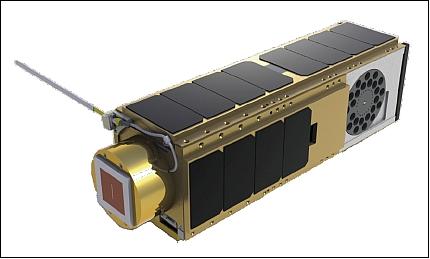
O/OREOS (Organism/ORganics Exposure to Orbital Stresses) Nanosatellite
Overview Spacecraft Launch Mission Status Experiments Ground Segment References
O/OREOS is a NASA/ARC (Ames Research Center) nanosatellite astrobiology research mission of PharmaSat and GeneSat mission heritage. The overall objective is to test how life and the components of life respond to the radiation environment in space. O/OREOS will carry selected organisms and organic compounds up into space and directly monitor the changes induced by the radiation and microgravity of the final frontier. The O/OREOS project is developed and conducted under the auspices of the NASA Astrobiology Small-Payloads Program; the payload initiative was established in 2008. 1) 2) 3) 4) 5) 6)
The mission goals include the demonstration of autonomous, in-situ biological organism and organic specimen exposure and detection technologies aboard a free-flying nanosatellite.
The O/OREOS nanosatellite will conduct its experiments over a period of 6 months. Upon completion of its mission, university students will operate the O/OREOS nanosatellite for educational purposes - as was done at SCU (Santa Clara University, CA) with GeneSat-1 (launch Dec. 16, 2006) and PharmaSat-1 (launch May 19, 2009).
Spacecraft
The O/OREOS nanosatellite uses a 3U CubeSat configuration with (34 cm in length) a maximum mass of 5.5 kg. The satellite attitude is controlled by permanent magnets and hysteresis rods that dampen the rotational energy. The satellite rotates about its long axis (z-axis) at a rate ranging from 1 to 2 rpm. The satellite also experiences a nutation, or "coning", rotation about its center of mass at a rate of 4-5 rpm with a cone half-angle of less than 13o. This spacecraft motion results in a microgravity environment that varies, but remains below 500 µg.
O/OREOS has a modified payload structural section, providing for dual modular payload experimental systems. The modified bus software and a new payload experiment control software are also being developed.
DOM (De-Orbit Mechanism): A simple deployable drag device is developed to assist the satellite with achieving natural orbit decay in less than 25 years. The device simply increases the surface area of the satellite (60% increase) by extending mylar panels. This results in a surface to mass ratio sufficient to achieve the required deorbit. No propellants are required. 7)
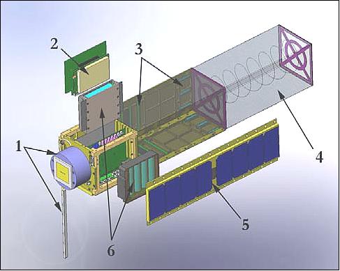
Legend to Figure 2: 1) UHF radio, 2) Microhard Radio, 3) Attitude Control, 4) Deployed de-orbit Mechanism, 5) Solar Array, 6) Battery Packs.
The DOM is built using two aluminum plates with a coiled spring attached between them. Four germanium-coated kapton sheets make up the outer walls of the device. These sheets along with the spring fold into a small form factor, and are fully enclosed by the aluminum plates.
Launch
O/OREOS was launched as a secondary payload on Nov. 20, 2010 (UTC) from Kodiak Island, Alaska. The primary mission is referred to as: "USAF STP-S26 mission." The launcher is a Minotaur-IV expendable launch vehicle of OSC. 8)
The O/OREOS nanosatellite uses the P-POD (Poly-Picosatellite Orbital Deployer) mechanism for deployment.
Orbit: a circular orbit of 650 km altitude with an inclination of 72o; the orbital period is 97.7 minutes.
RF communications: S-band and Amateur radio communications in UHF/VHF. The S-band link uses the commercial Microhard MHX-2420 COTS transceiver. 9)
The Microhard MHX2420 can be an inexpensive, powerful tool for space-to-ground communications. Following a myriad of tests, the Microhard MHX2420 has been characterized and optimized for space operation, proving to be reliable when properly configured. Tests indicated that five main configuration settings impact the data throughput of the radios: baud rate, wireless link rate, max packet size, FEC, and hop interval. Changing each setting has tradeoffs and should be configured to meet the specifications of a specific mission. In optimizing these configurations, the Microhard MHX2420 stands out as one of the best options for low cost Nanosatellite missions. 10)
Mission Status
• Feb. 2014: The results from the exposure of the metalloporphyrin iron tetraphenylporphyrin chloride (FeTPPCl) to the outer space environment, measured in situ aboard the O/OREOS nanosatellite, are reported in the following reference. 11)
• In early 2012, NASA's O/OREOS CubeSat mission has successfully carried out microorganisms and monitored the effects of the space environment on their growth and metabolism. The mission is the first demonstration flight of the 'small payload initiative' for the ASTID (Astrobiology Science and Technology Instrument Development) element of NASA's Astrobiology Program. 12) 13) 14)
• In the fall of 2011, nearly 100,000 beacon packets have been submitted by amateurs in 20 countries. About 6 MB of data have been downlinked and processed by the Santa Clara University operation team through S-band (WiFi) bidirectional radio. In addition to the science results from both payloads, these data include measurements of the radiation dose, rotation data, temperature, and health status of the spacecraft. Multiple commands were uplinked successfully to tune operational parameters. 15)
All three biological experiments using the SESLO payload are complete; they were executed on Dec. 3, 2010, Feb. 18 and May 19, 2011. From the SEVO experiment, the project observed nominal spectrometer function, and so far 24 sets of 24 UV-visible spectra have been recorded and downlinked, amounting to nearly 600 spectra from 4 organic sample types embedded in 4 microenvironments.
- The SESLO data contribute to the understanding of the environmental limits of life and will address many aspects of space biology and planetary protection
- The SEVO data allow the project to better understand the carbon chemistry in space environments, extraterrestrial delivery processes and prebiotic chemistry on the early Earth (Ref. 15).
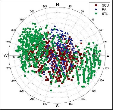
• As of June 2011, the automated beacon network has received over 2,100 O/OREOS beacon packets, resulting in an average of nearly 11 packets/day. This is enough to satisfy operator confidence in the satellite's nominal state of health during periods when standard operations are not being conducted. Packets are received over 75% of the time (e.g., on 3 out of 4 days), with an average time of roughly 9 hours between passes where a beacon packet was received. Beacon packets are typically received during passes with a maximum elevation greater than 50o, which occur at one or more of the three receive-only stations each day. The azimuth-elevation distribution of beacon packets received by each receive-only station over a 3-month period is shown in Figure 3. Note that the beacon packets received at lower elevations by the STL (St. Louis) station are the result of experimenting with an antenna setup which is oriented in a direction other than straight up. 16)
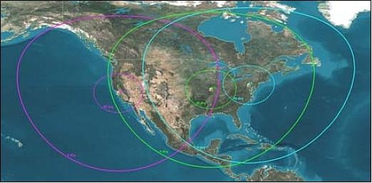
- Current automated beacon receive stations are located in Pennsylvania (PA), at St. Louis University in St. Louis, Missouri (STL), and on the SCU campus in Santa Clara, CA (Figure 16); an additional station is located at the University of Hawaii in Manoa Hawaii, but is not operational for the O/OREOS mission.
- Various satellite anomalies have been detected using the automated beacon health monitoring network, to include low battery voltage, unexpected system resets, and off-nominal temperature conditions. In addition, a number of receive-only station anomalies have been detected, which are typically attributed to dropped Internet connections, but events such as facility reconfigurations and power outages have also been detected. Overall, the use of the automated satellite beacon health monitoring network has resulted in a significant reduction of required on-console time by human operators, and the beacon network has become a standard part of Santa Clara University's satellite operations environment. The beacon network also provides an operational testbed for maturing SCU's expertise in model-based reasoning for anomaly management. Model-based reasoning algorithms have been incorporated into the system and favorable results have been obtained with the use of an integrated model-based reasoning system for anomaly detection and diagnosis in the O/OREOS operational space system. Future work includes refined integration of model-based reasoning systems for more precise and focused anomaly detection and diagnosis, as well as the support of anomaly resolution activities within the ground segment.
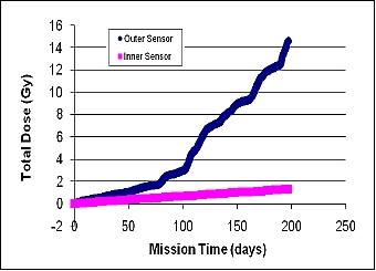
- RadFET sensors: Though both sensors produced reasonable values, the overall dosage was lower than originally predicted (Figure 4). The "Outer Sensor" is not shielded at all on one side, and the "Inner Sensor" is shielded by the equivalent of ~ 5 mm of aluminum.
Externally, the lower dose can be explained at least in part by shielding that the spacecraft effectively provides for the sensor, as it was exposed on only one side and the calculation assumed hemispherical (2? steradian) exposure. Using the RadFET-measured dose and the SPENVIS calculations to establish a most probable range of dose, the organic compounds received a total dose of 6 - 30 Gy over 6 months after accounting for the 1.5 mm thick MgF2 window behind which each film resides.
• In early March 2011, the nanosatellite continues to send its data to the project team at NASA/ARC. 17) 18) 19)
• On Feb. 18, 2011, the second part of the SESLO biological experiment began and also was successfully finished in one day. The experiment is designed to characterize the growth, activity, health and ability of microorganisms commonly found in soil and salt ponds in a dried and dormant state - Bacillus subtilis and Halorubrum chaoviatoris – to adapt to the stresses of outer space by rehydrating, or "feeding," and growing them using dyed liquid nutrients. Scientists will compare the microbes' population density and change in color at three different times during the mission to determine how and if their behavior changes with longer exposure to radiation and weightless conditions in space (Ref. 18).
• On Dec. 3, 2010, two weeks after O/OREOS deployed, the first of three biological experiments began operating automatically within the SESLO (Space Environment Survivability of Living Organisms) payload; and was successfully completed just 24 hours later (Ref. 18).
• After a spacecraft checkout period, O/OREOS autonomously initiated the first of two experiments, which will last approximately six months and transmit data for as long as a year (Ref. 20).
• The ground station of SCU (Santa Clara University) made soon contact with the O/OREOS nanosatellite confirming that the spacecraft successfully deployed and initiated the first experiment. The amateur radio community also has been listening to O/OREOS and giving the operations team important information about the health and status of the spacecraft. 20)
Experiment Complement
There are two experiment payloads that include specimens. One experiment payload includes two biological specimens, while the other payload includes four types of reaction cells containing organic molecules. The general mission scenario involves exposing selected organisms and organic compounds to the space environment, and monitoring or assessing changes to them induced by space exposure. Both of these experiments are of great interest in the new discipline called astrobiology.
Each payload includes the electronics, microcontroller, and data storage in an autonomous stand-alone package requiring only a standard power and-data interface.
SESLO (Space Environment Survivability of Living Organisms) experiment
The objective of the SESLO experiment is to characterize the growth, activity, health and ability of microorganisms to adapt to the stresses of the space environment. The experiment contains two types of living biological specimens, with active optical measurement of growth and/or metabolic activity.
The experiment is sealed in a vessel at one atmosphere and contains two types of microbes commonly found in salt ponds and soil. The microbes are stored in the experiment modules in a dried and dormant state: Halorubrum chaoviatoris and Bacillus subtilis. After O/OREOS reaches orbit, the experiment will initiate and begin to rehydrate, or "feed," and grow three sets of the microbes at three different times: the first growth test occurs within 1-2 weeks after launch, the next in three months and the final test occurs at six months after launch. Each growth test occurs in its own module, thermally isolated from the other two.
The payload uses time-resolved optical density and absorbance measurements to track growth and metabolism of the organisms. The growth data are stored in memory and downlinked by the operations team (Ref. 6).
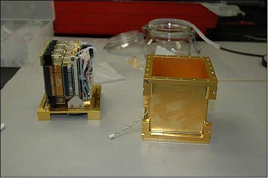
The experiment contains three modules, each of which includes six 75 µL microfluidic wells of each species (Figure 6). The biology is loaded into the modules, air dried to impart a condition of stasis, and rehydrated on orbit with growth media, which cause viable cells to resume growth and reproduction. The modules are rehydrated at three timepoints during the mission to measure to effects of microgravity and cumulative radiation dose.
The first module is rehydrated immediately after launch, the second module is rehydrated after three months of exposure, and the final module is activated after six months. Relative to a companion ground control experiment, differences in growth patterns among the three flight modules should be attributable to the different radiation doses.
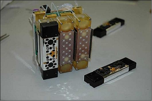
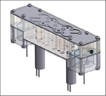
Each module (Figure 7) contains a combination of reservoirs, microfluidic channels, sensors, and valves that control the flow of growth media to the biological specimens in the microwells. Six temperature sensors and a heater are installed on each module. Pressure and relative humidity are also measured inside the payload container. A diaphragm air pump maintains pressure, via elastomeric membranes, on the fluid reservoirs housed within the biomodules whenever one of the modules is in organism-growth mode. Gas-permeable membranes covering the microwells allow exchange of oxygen and CO2 with the atmosphere inside the payload container during growth. Embedding fluidic reservoirs within the modules and flying dry biology, with survival of more than eight months demonstrated in ground testing prior to integration and launch, were two major developments for the NASA team. These advances make a more volume-efficient fluidic system, reduce the number of plumbing connections, and enable storage of specimens in stasis for longer durations than "wet stasis."
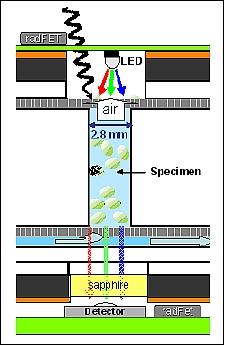
The growth of the biological specimens is measured via optical absorbance and density, a technique with heritage from the PharmaSat mission. A dedicated tricolor LED illuminates along the axis of each well and a detector at the opposite end of the well reads the intensity for each color in turn.
In the case of B. subtilis, the redox metabolism indicator dye Alamar Blue provides a blue-to-pink color change as a consequence of cellular metabolism. Microbial growth is quantified in real time for both organisms in three wavelength bands: 470, 525, and 615 nm, for up to 17 days from growth initiation. For B. subtilis, the 470 nm band primarily tracks optical density, while the 525 nm band detects increases in the reduced form of Alamar Blue (pink), and the 615-nm band registers decreases in the oxidized form (blue). For Hrr. chaoviatoris, all 3 wavelengths track optical density, but there is slightly larger (and quantifiable) absorbance at 470 nm than the other 2 wavelengths due to the carotene produced by this halophile, providing growth information complementary to the optical density.
To better expose the biology to space radiation, the aluminum pressure vessel necessary to keep air in the payload was thinned on the side nearest to the samples. This required additional shielding internally for the payload electronics. To adequately shield the detector without blocking transmitted light, a sapphire window (similar radiation attenuation to aluminum metal) was placed between it and the radiation path through the well. Radiation doses are measured with radiation-sensitive field-effect transistors (RadFETs); their output will be included with all growth telemetry. Figure 8 shows a cross section of a biological sample well.
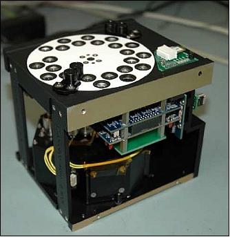
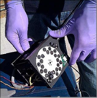
SEVO (Space Environment Viability of Organics)
The SEVO experiment monitors the stability, modification, and degradation of organic molecules in thin-film form—in model environments including interplanetary/interstellar space, the lunar surface, wet/salty environments, and the Martian atmosphere—by providing four experimental "microenvironments" within miniature reaction cells of chemical building blocks of life in our Solar System and beyond. 21) 22)
Thin films of each of the four astrobiologically significant organic molecules are housed in the four different microenvironments and the chemical consequences of their exposure to solar UV, visible light, and space ionizing radiation will be monitored periodically by UV-visible spectroscopy over the 6-month mission time span.
The payload includes a highly capable UV-visible-NIR spectrometer, a 24-sample carousel, and integral optics enabling use of the Sun as light source for spectroscopy. The spectrometer was designed and built by Aurora Design and Technology and shares heritage from the NASA missions LCROSS (Lunar CRater Observation and Sensing Satellite) and LADEE ( Lunar Atmosphere and Dust Environment Explorer). The thermally stable instrument provides 1–2 nm spectral resolution, < 0.1 nm spectral band-shift-measurement capability, 0.03 absorbance-unit resolution, and covers the 200 – 1000 nm wavelength range. The CCD acquires a single spectrum in 100 ms or less; multiple spectral acquisitions (e.g., 16 full spectra acquired in 1.6 s) can be averaged to improve signal-to-noise ratios.
To use the Sun as the light source for UV-visible spectroscopy, a pair of baffled diffuser assemblies is included to ensure that the organic sample film under interrogation by the spectrometer is uniformly illuminated over a 3 mm diameter spot with light intensity that varies by no more than ±25% for sun angles between ±35o from normal. Integral solar intensity sensors provide synchronous light intensity measurements with each spectral acquisition.
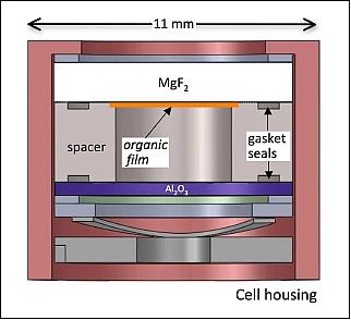
The hermetically sealed reaction cells (Figure 10) are similar to those used for the EXPOSE experiment currently in orbit on the ISS, with the important difference that the SEVO cells use room temperature indium cold-weld sealing of the optical windows following organic film deposition on windows. Each of the four organic materials is vacuum sublimed onto several MgF2 windows, which allow UV-visible irradiation of the samples at wavelengths as short as 124 nm; some of the windows have either SiO2 or Al2O3 thin coating layers between the organic and the MgF2 to tune the optical bandpass and/or provide a chemically relevant substrate pertinent to the defined microenvironment.
A sapphire window (with high optical transparency across the spectrometer's 200–1000 nm range) is used on the far side, where light enters the collection optic and is routed via optical fiber to the spectrometer. Both windows are cold welded to a stainless-steel spacer, using indium gasket seals, inside a glovebox, thus creating a hermetically sealed microenvironment with the desired simulated atmosphere. The sealed cells are then assembled in 11 mm diameter housings and installed into the rotatable payload carousel. The housing and carousel protect the fragile windows from damage in the launch environment.
To maximize the number of cells in the carousel, the samples were staggered and divided into two concentric rings. Two optical fibers are located under the carousel; however, only one fiber at a time is illuminated owing to the cell spacing. The fiber outputs are combined for input to the spectrometer.
When in orbit, the magnetically-stabilized satellite is expected to rotate about its long axis at a rate of 1-2 rpm. Given the absence of active attitude control, SEVO requires that baffled solar intensity sensors be located on the front of the payload to provide simple sun-pointing information. As the exposed face of the SEVO instrument rotates through an angle at which an adequate level of solar intensity for measuring a UV-visible spectrum is detected (Figure 11), the spectrometer is turned on and returns 16 averaged spectra for the current cell collected near the peak intensity for that rotation of the satellite.
Acquiring 16 consecutive spectra during peak solar intensity and averaging them provides a comparatively high signal-to-noise ratio. A combination of adequate baffling and high acquisition thresholds mitigate false positives from Earth/Moon shine.
Ground Segment
The O/OREOS mission operations subsystem consists of the distributed ground segment facilities, components, and functionalities that have been designed and selected for meeting the needs of the GeneSat-1 O/OREOS PharmaSat mission. Significant portions of this system are currently in use to support on-orbit mission operations for the GeneSat-1 and PharmaSat satellites.
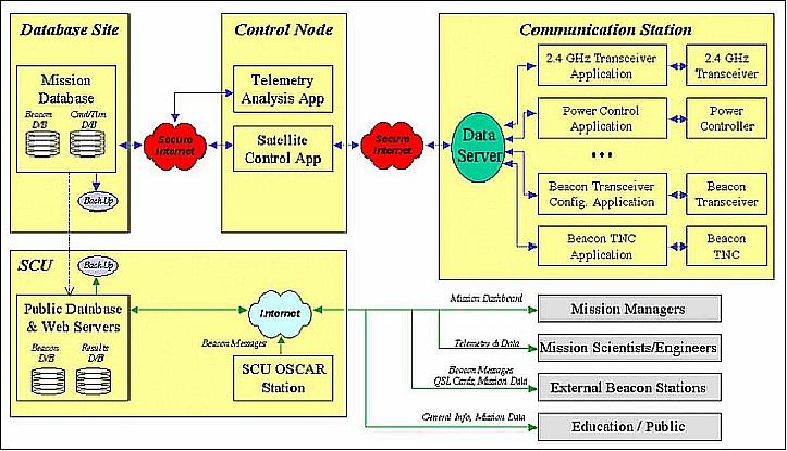
The Control Node and Communication Station are connected via a secure, public internet connection which includes both wired and wireless links. Commands are selected at operator workstations at the Control Node(s), with the equivalent validated command bit pulled from the mission database. When commands are sent, they travel from the Control Node to the operational communication station via secure internet, are converted to S-band radio commands, and broadcast to the spacecraft by the communication station antennae. Satellite telemetry travels in a similar manner in the reverse direction (Ref. 6).
The satellite also broadcasts a simple, periodic UHF beacon signal, which is received by UHF stations within the ground segment as well as by public operators. Beacon messages received by external users (in the educational and ham radio community) may be forwarded to the Mission Operations team via a public web page; messages are archived and available for public perusal, and an automated QSL card is returned to the external user submitting the packets as per tradition in the amateur radio community.
Mission operations for O/OREOS are conducted using an internet-based, geographically-distributed command and control network that is owned and operated by Santa Clara University (SCU) and which has been used over the past decade to support numerous satellite and robotic missions. The ground segment architecture includes a centralized mission control center on the Santa Clara campus in northern California with back-up control nodes at NASA/ARC (Ames Research Center).
Figure 13 depicts the notional command and data handling architecture across the ground segment. Using a channel subscription model, a streaming data server allows distributed software applications to be easily interfaced. Contact operations software at the Control Node connects to communication station equipment control applications as well as the mission database in order to allow an operator to remotely configure the communication station, select preapproved spacecraft commands, transmit commands to the satellite, receive satellite telemetry that is subsequently archived in the mission database, etc. This contact operations software infrastructure is distinct from the servers and software that support data dissemination with managers, scientists, engineers, and the public.
Control Nodes are located in the NASA/ARC MMOC (Multi-Mission Operations Center), the CREST (Center for Robotic Exploration and Space Technologies) operations center in the NASA Research Park, the SCU (Santa Clara University) Satellite Operations Lab on the SCU campus (Santa Clara, CA), and within all communication stations configured for use. Additional Control Node locations may be easily added to the network. The underlying technical design makes this very simple to do; however, limits are placed on doing this in practice for security and configuration control reasons.
A variety of functional processing is performed by the mission operations team at SCU in order to support the O/OREOS mission. Functions include command planning and formatting, telemetry processing and analysis, data archiving, orbit analysis, health analysis and anomaly management, and mission planning.
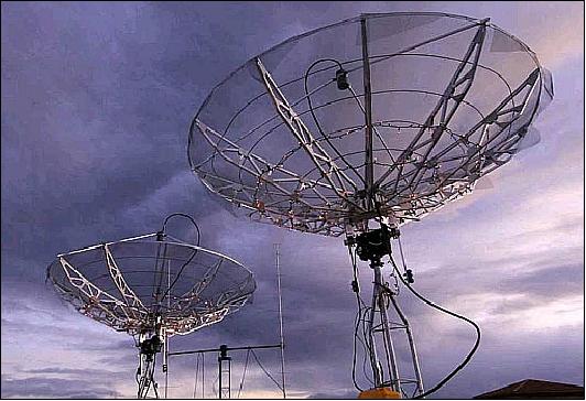
The command and data handling architecture of the mission operations system allows for the operation of numerous communication stations in support of the O/OREOS mission. The primary stations will include the SCU Dual S-band station and the SCU UHF Yagi station, both located on the SCU campus (Figure 14).
The UHF/VHF station is used to verify operation of the amateur radio beacon; the beacon has been included on O/OREOS to support participatory mission operations as part of the program's education and outreach efforts. The UHF/VHF station is an OSCAR-class station typical of those used by amateur radio operators. It consists of dual-Yagi antenna driven by a programmed track antenna pointing system. Additional equipment includes transceivers, a terminal node controller (packet modem), and data processing components/workstations for the command/telemetry channel.
Automated Beacon Network for Anomaly Detection: Beacon monitoring is a spacecraft mission operations architecture that, for certain mission classes, can provide cost-effective anomaly detection and notification capabilities. A health message is periodically broadcast by the spacecraft and received by a network of geographically distributed low-cost automated receiving stations. The message is forwarded to a central monitoring workstation, which can perform additional telemetry filtering and which then notifies on-call operators and initiates response actions as necessary. Beacon monitoring has been explored for a wide variety of spacecraft missions, to include spacecraft constellations such as the GPS (Global Positioning System), the DSCS (Defense Satellite Communications System), the DS1 (Deep Space 1) mission of NASA/JPL, and the Sapphire microsatellite mission of Stanford University. However, these missions either did not adopt the beacon monitoring concept or only implemented beacon monitoring in the form of prototype operations or in ground test scenarios (Ref. 16).
SCU's automated beacon network is the first example of an operational satellite beacon-based health monitoring network, having obtained flight results during end-of-life operations for the GeneSat-1 mission and during standard operations for the O/OREOS mission.
The SCU beacon network system consists of the O/OREOS satellite, networked and automated receive-only beacon stations, and a central monitoring station, as shown in Figure 15. Stations receive the packets opportunistically as the spacecraft orbits the Earth, periodically broadcasting its signal. O/OREOS is particularly well suited for support by a beacon monitoring network, as the beacon transmitter broadcasts packets (health messages) every five seconds containing critical telemetry information such as solar panel electrical currents, payload temperatures, and battery voltage, which are sufficient for health analysis.

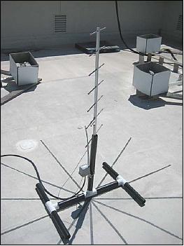
Current beacon network stations are located in Pennsylvania, at St. Louis University in St. Louis, Missouri, and on the SCU campus in Santa Clara, CA. The geographical distribution of the beacon stations, shown in Figure 16, provides the capability of receiving beacon packets over consecutive passes, resulting in enhanced timeliness of state-of-health updates. The stations use a vertically pointed, directional, 7-element Yagi antenna and simple amateur radio reception equipment, connected to a networked computer. The antenna provides enhanced gain for high elevation passes, while limiting the station's ability to receive packets at lower elevations. Figure 17 shows a typical antenna installation.
Packets received by the stations are forwarded to the central monitoring station via secure Internet connections. At the central monitoring station, health monitoring tasks such as data handling, anomaly detection, and operator notification are implemented using MATLAB, Satellite Tool Kit (STK), and MySQL database. Anomaly detection is accomplished by implementing a set of rules to check the health of the satellite as well as the functionality of the beacon network. Upon receiving a beacon packet, the rules are used to perform basic telemetry limit checks to ensure nominal operating conditions. In addition to "packet" rules, another set of rules is checked daily to ensure that the receive-only stations are receiving packets if the satellite has passed over the station with a high enough elevation. In the event that any rule is violated, on-call operators are notified via email or text message (SMS), whereby appropriate actions are taken, such as performing full state-of-health contact operations via the two-way S-band communications link and/or reconfiguring systems as necessary to restore the satellite and the beacon network to nominal functionality.
References
1) NASA Factsheet, URL: http://www.nasa.gov/pdf/467036main_OOREOS_FactSheet_FINAL_2010-10-29.pdf
2) http://www.spacedaily.com/reports/Outer_Space_Oreos_999.html
3) P. Ehrenfreund, A. Ricco, J. Hines, D. Squires, B. Yost, R. Mancinelli, A. Mattioda, W. Nicholson, R. Quinn, O. Santos, C. Conley, "The O/OREOS Sat Mission: New Science and Technologies for Autonomous Small Satellite Payloads," Proceedings of the 60th IAC (International Astronautical Congress), Daejeon, Korea, Oct. 12-16, 2009, IAC-09.B4.2.11
4) John W. Hines, "Free Flyer Utilization for Biology Research," URL: http://spacepolicyonline.com/pages/images/stories/Hines_microg_aug_09.pdf
5) John W. Hines, "ARC Nanosatellite Spacecraft and Missions - Current and Planned Activities," VKI (Von Karman Institute for Fluid Dynamics), Rhode-St-Genese, Belgium, Nov. 19, 2009, URL: http://www.vki.ac.be/QB50/download/workshop/papers_17nov/hines.pdf
6) Giovanni Minelli, Antonio Ricco, Christopher Beasley, John Hines, Elwood Agasid, Bruce Yost, David Squires, Charlie Friedericks, Matthew Piccini, Greg Defouw, Mike McIntyre, Robert Ricks, Macarena Parra, Millan Diaz-Aguado, Linda Timucin, Mike Henschke, Matthew Lera, Ming Tan, Mike Cohen, Karolyn Ronzano, Ed Luzzi, Nghia Mai, Aaron Schooley, Dianna Ly, Eric Stackpole, Jeffrey Lin, John Tucker, Pascale Ehrenfreund, Rocco Mancinelli, Andrew Mattioda, Wayne Nicholson, Richard Quinn, Orlando Santos, Nathan Bramall, Kathryn Bryson, Julie Chittenden, Cindy Taylor, Amanda Cook, David Landis,Christopher Kitts, Mike Rasay, Ignacio Mas, Michael Neumann, Anne Mahacek, Anthony Young,
Laura Bica, "O/OREOS Nanosatellite: A Multi-Payload Technology Demonstration," Proceedings of the 24th Annual AIAA/USU Conference on Small Satellites, Logan, UT, USA, Aug. 9-12, 2010, SSC10-VI-1, URL: http://webpages.scu.edu/ftp/iamas/papers/SSC10-VI-1_Minelli_OOREOS.pdf
7) Eric Stackpole, "De-Orbit Mechanism for a Small Satellites," CalPoly Developers' Workshop, San Luis Obispo, CA, USA, April 22-25, 2009
8) http://ooreos.engr.scu.edu/dashboard.htm
9) http://www.microhardcorp.com/brochures/MHX2420.OEM.Brochure.Rev.3.1.pdf
10) Stuart Kearney, Mark R. Lombardi, Watson Attai, Ken Oyadomari, Ahmed Saleh Nasser Al Rumhi, Sébastien Rakotonarivo, Loic Chardon, Oriol
Tintore Gazulla, Jasper Wolfe, Alberto Guillen Salas, Jon DeWald, Richard Alena, "Microhard MHX2420 Orbital Performance Evaluation Using RT Logic T400CS," Proceedings of the 26th Annual AIAA/USU Conference on Small Satellites, Logan, Utah, USA, August 13-16, 2012
11) Amanda M. Cook, Andrew L. Mattioda, Antonio J. Ricco, Richard C. Quinn, Andreas Elsaesser, Pascale Ehrenfreund, Alessandra Ricca, Nykola C. Jones, Soren V. Hoffmann, "The Organism/Organic Exposure to Orbital Stresses (O/OREOS) Satellite: Radiation Exposure in Low-Earth Orbit and Supporting Laboratory Studies of Iron Tetraphenylporphyrin Chloride," Astrobiology. February 2014, Vol. 14, Issue 2, pp: 87-101, doi:10.1089/ast.2013.0998
12) "O/OREOS Nanosatellite Success in Orbit," Space Daily, March 26, 2012, URL: http://www.spacedaily.com/reports/O_OREOS_Nanosatellite_Success_in_Orbit-999.html
13) Wayne L. Nicholson, Antonio J. Ricco, Elwood Agasid, Christopher Beasley, Millan Diaz-Aguado, Pascale Ehrenfreund, Charles Friedericks, Shakib Ghassemieh, Michael Henschke, John W. Hines, Christopher Kitts, Ed Luzzi, Diana Ly, Nghia Mai, Rocco Mancinelli, Michael McIntyre, Giovanni Minelli, Michael Neumann, Macarena Parra, Matthew Piccini, R. Mike Rasay, Robert Ricks, Orlando Santos, Aaron Schooley, David Squires, Linda Timucin, Bruce Yost, Anthony Young, "The O/OREOS Mission: First Science Data from the Space Environment Survivability of Living Organisms (SESLO) Payload," Astrobiology, Vol. 11, Issue 10, Dec. 2011, pp. 951-958, doi:10.1089/ast.2011.0714
14) Aaron L. Gronstal, "O/OREOS Nanosatellite Success in Orbit," Astrobiology Magazine, March 22, 2012, URL: [web source no longer available]
15) P. Ehrenfreund, A. J. Ricco, R. Quinn, N. Bramall, K. Bryson, J. Chittenden, A. Cook, R. Mancinelli, A. Mattioda, G. Minelli, W. Nicholson, O. Santos, D. Squires, C. Friedericks, C. Kitts, R. Rasay, and the O/OREOS-Sat Engineering Team at NASA Ames, " Proceedings of IAC 2011 (62nd International Astronautical Congress), Cape Town, South Africa, Oct. 3-7, 2011, paper: IAC-11.B4.2.1
16) Christopher Kitts, Mike Rasay, Laura Bica, Ignacio Mas, Michael Neumann, Anthony Young, Giovanni Minelli, Antonio Ricco, Eric Stackpole, Elwood Agasid, Christopher Beasley, Charlie Friedericks, David Squires, Pascale Ehrenfreund, Wayne Nicholson, Rocco Mancinelli, Orlando Santos, Richard Quinn, Nathan Bramall, Andrew Mattioda, Amanda Cook, Julie Chittenden, Katie Bryson, Matthew Piccini, Macarena Parra, "Initial On-Orbit Engineering Results from the O/OREOS Nanosatellite," Proceedings of the 25th Annual AIAA/USU Conference on Small Satellites, Logan, UT, USA, Aug. 8-11, 2011, paper: SSC11-III-3
17) P. Ehrenfreund, A. J. Ricco, R. Quinn, N. Bramall, K. Bryson, J. Ch ittenden, A. Cook, R. Mancinelli, A. Mattioda, G. Minelli, W. Nicholson, O. Santos, D. Squires, C. Kitts, R. Rasay, A. Young, and the O/OREOS-Sat Engineering Team at NASA Ames, "The O/OREOS Mission - Astrobiology Data Collected in low Earth orbit," Lunar and Planetary Science Conference, March 7-11, 2011, URL: http://www.lpi.usra.edu/meetings/lpsc2011/pdf/1918.pdf
18) Rachel Hoover, "NASA Nanosatellite Celebrates 100 Days In Space Studying Life," NASA, March 2, 2011, URL: http://www.nasa.gov/centers/ames/news/features/2011/o-oreos_100_days.html
19) http://www.nasa.gov/mission_pages/smallsats/ooreos/main/
20) Rachel Hoover, "O/OREOS Reaches Orbit, Begins Astrobiology Experiments," NASA News, Nov. 23, 2010, URL: http://www.nasa.gov/centers/ames/news/releases/2010/10-109AR.html
21) Nathan E.Bramall, RichardQuinn, AndrewMattioda, KathrynBryson, JulieD.Chittenden, Amanda Cook , CindyTaylor, GiovanniMinelli, PascaleEhrenfreund, AntonioJ.Ricco, David Squires, OrlandoSantos, CharlesFriedericks, DavidLandis, NykolaC.Jones, Farid Salama, LouisJ.Allamandola, SorenV.Hoffmann, "The developmentoftheSpaceEnvironmentViabilityofOrganics(SEVO) experimentaboardtheOrganism/OrganicExposuretoOrbitalStresses (O/OREOS)satellite," Planetary andSpaceScience, Vol. 60, 2012, pp: 121–130, URL: http://www.gwu.edu/~cistp/assets/docs/research/articles/Ehrenfreund_SEVO_O-OREOS.pdf
22) Andrew Mattioda, Amanda Cook, Pascale Ehrenfreund, Richard Quinn, Antonio J. Ricco, David Squires, Nathan Bramall, Kathryn Bryson, Julie Chittenden, Giovanni Minelli, Elwood Agasid, Lou Allamandola, Chris Beasley, Roland Burton, Greg Defouw, Millan Diaz-Aguado, Mark Fonda, Charles Friedericks, Chris Kitts, David Landis, Mike McIntyre, Michael Neumann, Mike Rasay, Robert Ricks, Farid Salama, Orlando Santos, Aaron Schooley, Bruce Yost, Anthony Young, "The O/OREOS Mission: First Science Data from the Space Environment Viability of Organics (SEVO) Payload," Astrobiology, Vol. 12, No 9, 2012, DOI: 10.1089/ast.2012.0861, URL: [web source no longer available]
Overview Spacecraft Launch Mission Status Experiments Ground Segment References Back to Top