NEMO-AM (Nanosatellite for Earth Monitoring and Observation-Aerosol Monitoring)
EO
Atmosphere
Aerosols
Aerosol absorption optical depth (column/profile)
Quick facts
Overview
| Mission type | EO |
| Agency | UTIAS / SFL |
| Mission status | Planned |
| Measurement domain | Atmosphere |
| Measurement category | Aerosols |
| Measurement detailed | Aerosol absorption optical depth (column/profile), Aerosol optical depth (column/profile), Aerosol Extinction / Backscatter (column/profile), Aerosol effective radius (column/profile), Aerosol Layer Height |
| Instruments | Imager |
| Instrument type | Other, Atmospheric chemistry, Communications, Data collection |
| CEOS EO Handbook | See NEMO-AM (Nanosatellite for Earth Monitoring and Observation-Aerosol Monitoring) summary |
NEMO-AM (Nanosatellite for Earth Monitoring and Observation-Aerosol Monitoring)
Overview Spacecraft Launch Sensor Complement Ground Segment References
The NEMO bus represents a technology evolution to the UTIAS/SFL (University of Toronto Institute for Aerospace Studies/Space Flight Laboratory) GNB (Generic Nanosatellite Bus) — providing a foundation for future high-performance nanosatellites.
The NEMO bus has a primary structure measuring 20 cm x 20 cm x 40 cm and is capable of peak power generation up to 80 W. A minimum of 30 W is available to the payload. The high peak power generation enables the NEMO bus to support a dedicated state-of-the-art high speed transmitter. The NEMO bus is designed with a total mass of 16 kg, 9 kg of which is dedicated to the payload. It can be configured for full three-axis control with up to 1 arcmin pointing stability.
GNB missions developed at UTIAS/SFL include AISSat-1 (launch July 12, 2010), UniBRITE/CanX-3A and BRITEAustria/CanX-3B (launch on Feb. 25, 2013), BRITE-Poland-1 (launch Nov. 13, 2013), BRITE-CA-1 and BRITE-CA-2 (launch June 19, 2014), CanX-4&5 (launch June 30, 2014), BRITE-Poland-2 (launch 2014).
The first spacecraft to use the new third-generation bus technology is the NEMO-AM (Aerosol Monitoring), a nanosatellite designed to perform multispectral observations in the VIS spectral range. The objective of NEMO-AM is to detect the aerosol content in the atmosphere with a ground resolution of up to 200 m. The NEMO-AM nanosatellite is partially funded by ISRO (Indian Space Research Organization) with the objective of detecting atmospheric aerosols in multiple bands over particular geographical areas with sub-degree accuracy. The project is being built under a collaborative agreement between UTIAS/SFL and ISRO. 1) 2) 3) 4)
ISRO will provide the scientific expertise and the science algorithm. The spacecraft will be controllable from two sites in the ground segment: SFL in Toronto and from an ISTRAC (ISRO Telemetry, Tracking and Command Network) facility in India, using SFL distributed ground station network technology.
Spacecraft
The NEMO-AM spacecraft bus is specifically being designed toward a level of performance that will redefine the state-of-the-art for nanosatellites. The satellite bus envelopes a volume of 20 cm x 20 cm x 40 cm; with up to 80 W peak power generation, the bus is capable of providing a minimum of 30 W to the payload. The larger payload capacity of up to 9 kg opens numerous payload possibilities, and the bus can be configured with state-of-the-art downlink and three-axes stabilization with up to one arcminute of pointing accuracy. The NEMO-AM spacecraft with a total mass of 16.1 kg, builds upon the heritage of the GNB hardware. 5) 6) 7)
Many of the hardware components on NEMO-AM are inherited from the GNB and likewise boast flight heritage. The satellite also employed new technologies facilitated by the COTS (Commercial off-the-Shelf) hardware. This facilitated shorter design cycles, but allowed those periods to be focused more on mission specific goals.
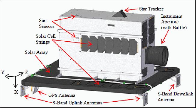
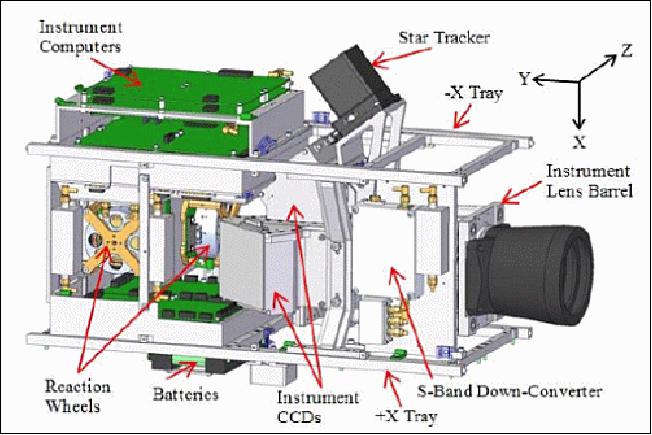
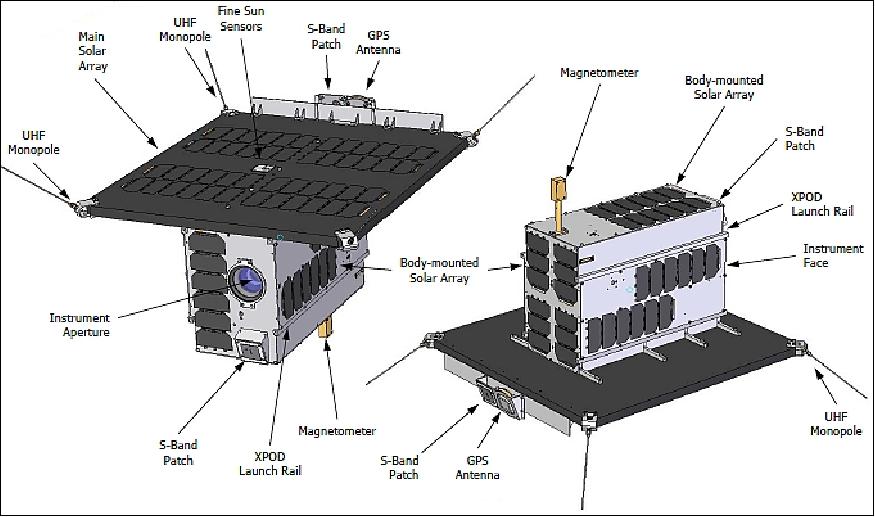
NEMO-AM will fly a standard suite of ADCS (Attitude Determination and Control Subsystem) components found on the GNB, a GPS receiver, communication antennas (S-band for uplink and downlink), onboard computers for task management, a power distribution network including batteries and solar cells, and a multi-spectral imager to capture aerosol concentration. The satellite's external features are shown in Figure 1.
The NEMO-AM structural subsystem uses a design concept that is based on an enhancement of SFL's proven GNB design. The primary developments implemented in the NEMO-AM bus consist of an improved payload carrying capability, along with a pre-deployed solar panel to meet more demanding power generation requirements.
At the core of the primary structure, a dual-tray system is used to support all subsystem components while facilitating rapid and flexible integration and testing. The trays also provide the primary load path from the satellite to the SFL XPOD Duo deployment system. An increased payload volume and a large pre-deployed solar array are allowed by the unique design features of the XPOD, which permit expansion of the bus outside of its internal (20cm x 20cm x 40cm) volume.
To achieve an optimal design that assures structural integrity while minimizing mass, NEMO-AM's primary structure, along with all brackets and internal panels, were manufactured using magnesium alloys. Oxidization resistance is critical for good electrical coupling of all metallic components, and as such all magnesium parts were plated using high-phosphorous electroless nickel. Space-rated plastics, such as Delrin and Tefzel, were used on the satellite, with an atomicoxygen-resisting coating applied on the surfaces directly exposed to space. The main solar array on the +X bus side consists of a total of 70 photovoltaic cells which are supported on a composite panel substrate that features a honeycomb structure sandwiched between two carbon fiber reinforced polymer facesheets.
An important part of the development work performed for the NEMO-AM structural subsystem were the finite element analyses under the launch environment mechanical loads, as well as under maximum cross-structure thermal gradients in on-orbit operations scenarios. For this purpose, increasingly detailed models were constructed for the preliminary and detailed designs, providing the basis for several revisions and improvements in the satellite configuration. Table 1 summarizes a number of general structural analysis cases and their results which drove the substantiation of the mechanical design.
Analysis | Verification criteria | Results |
Modal | Must exceed launch vehicle requirement in all axes | First natural frequency of spacecraft bus occurs at 192.5Hz |
Quasi-static acceleration | Structure must exhibit positive margin of safety at 12Gs in all axes | Maximum stresses of 35 MPa and 37.5 MPa emerging at trays-to-XPOD and payload-to-trays interfaces with positive margin |
Thermoelastic deformation | Design such that ADCS can tolerate angular misalignment between star tracker and payload under 30ºC cross-structure temperature gradient | Pointing error due to thermally induced deformation is less than 0.1º, accounted for in pointing error budget |
Ground operations | Structure mounted on mechanical ground support equipment has positive margin of safety under handling loads | Dedicated mounting points on structure, as well as support equipment, operating under 25% of material yield strengths |
OBC (On-Board Computer): NEMO-AM utilizes the distributed OBC architecture developed for the GNB. As part of this distributed architecture, dedicated tasks are assigned to individual OBCs. Figure 3 depicts the high level OBC architecture for NEMO-AM.
There are two distinct software modes for each OBC on NEMO-AM: bootloader and application. The bootloader supplies basic spacecraft telemetry, and an interface for uploading/storing and executing application software. Application software is powered by the CANOE (Canadian Advanced Nanospace Operating Environment). CANOE is a multi-threaded, real time, embedded operating system developed at SFL for use in a wide range of nanosatellite missions. A priority based round robin scheduler, inter-thread messaging, alarms and system clock allow for the execution of real-time embedded applications.
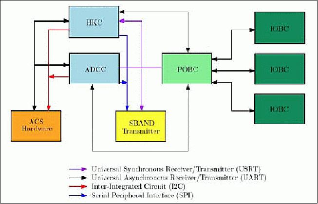
The application software packages powered by CANOE execute a host of different tasks onboard NEMO-AM. The HKC (Housekeeping Computer) is responsible for the collection of WOD (Whole Orbit Data), over-current protection and the execution of TTC (Time Tagged Commands). The ADCC (Attitude Determination and Control Computer) is responsible for all attitude control related tasks, such as collection of attitude telemetry, executing attitude algorithms/tasks and commanding of actuators. The POBC (Payload On-Board Computer) is responsible for all payload related operations. This includes commanding individual imagers through three IOBCs (Instrument On-Board Computers), transferring observation data into onboard Flash and high speed transmission of payload data to the ground. In addition to processing tasks, data storage is also distributed across the different OBCs. Data collected on an OBC is stored locally on a NAND Flash chip, managed by a Flash file system developed in-house at SFL.
The implementation of the distributed OBC architecture allows for independent real time tasks to be executed simultaneously. Spacecraft attitude control is executed independent of CPU and bus loads created by payload or housekeeping operations. Additional power savings benefit arises from the fact that individual OBCs can be powered off without the operation of the others.
ADCS (Attitude Determination and Control Subsystem): The ADCS derives overall heritage from previous GNB missions, but implements new timing, guidance and navigation solutions which enable sub-degree Earth observation. These solutions are tailored in a modular manner which allows different terrestrial-based missions and hardware suites to leverage the technology.
The sensor suite on NEMO-AM is composed of six SFL sun sensors, one SFL magnetometer and a star tracker of SI (Sinclair Interplanetary). Sunlit coarse pointing, to an accuracy of better than 5°, is achieved using the SFL sun sensors and magnetometer. In eclipse, the attitude estimation solution is corrected only by the magnetometer. The star tracker is necessitated by the sub-degree pointing requirements and by implementing it as the only sensor during Earth observation, an attitude navigation solution of 0.036° (2σ) is achieved through the AEKF (Attitude Extended Kalman Filter). The actuator suite on NEMO-AM is composed of three SI reaction wheels and three SFL magnetorquers. The reaction wheels are the primary means of attitude control, providing 60 Nms of momentum storage and applying up to 2 mNm of torque, while having a maximum torque jitter of 5 x 10⁻⁵Nm. The magnetorquers are current-controlled up to 100 mA and, are used to dump momentum and exit poor attitudes when in safehold conditions. Although not an attitude sensor, a Novatel OEMV-1 series GPS receiver is used to obtain an orbital state solution. This solution is later corrected through an OEKF (Orbital Extended Kalman Filter ) to achieve an orbital navigation solution of 12 m (2σ) in position and 6 cm/s (2σ) in velocity. The various attitude hardware are depicted in Figure 4.
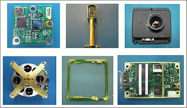
Legend to Figure 4: Top, from left to right: SFL sun sensor, SFL boom-mounted magnetometer, SI star tracker. Bottom, from left to right: SI reaction wheel, SFL magnetorquer, Novatel GPS receiver.
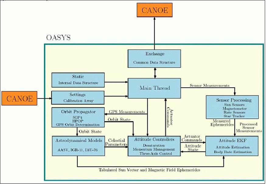
The ADCS is managed by the ADCC, which executes the OASYS (Onboard Attitude System Software) flight code on the computer operating system CANOE. OASYS encompasses all of the necessary ephemerides (IGRF-11, sun vector, FK5), orbit propagators (SGP4, gravity models), navigation filters (AEKF and OEKF), guidance solutions, control laws and ADCS management/housekeeping logic. An ADCS thread is executed on the ADCC once every second, where raw hardware telemetry is collected and passed to OASYS, telemetry is then interpreted, filtered and synchronized, celestial and trajectory algorithms are effected, control and actuator commands are synthesized and finally actuators commanded. A high-level flow diagram of OASYS is shown in Figure 5.
Control is achieved by using a state feedback proportional-derivative-integral law to regulate the quaternion and angular velocity errors with respect to the guidance trajectory. The compensation of gyroscopic terms, feed-forward of angular accelerations and linearization of the trajectory all aid in Earth observation. In-house simulations, which incorporate hardware models derived from unit-level tests, celestial models of the orbital environment and, truth models of the spacecraft and orbit dynamics, demonstrate that the ADCS is able to constantly track a target accurately to within 0.8° and with a stability of less than one tenth of a pixel.
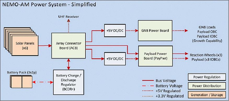
EPS (Electrical Power Subsystem): The EPS is customized to the instrument loads and mission specific operations throughout the different stages of the mission. Similar to other subsystems, the electronics chosen to build the power system were selected based on radiation testing. The primary means of power generation are 28% triple-junction solar cells. Each satellite face has at least a single string made up of 7 solar cells for keep-alive power generation. The large +X solar array shown on the left of Figure 6 is composed of 8 of these 7-cell strings and provides the principal means of power generation on NEMO-AM. The maximum power generation under worst case temperature end of life conditions is 48 W.
Power from the solar arrays and battery is distributed through regulated power buses. The main power bus is programmable to operate up to 26 V. Power to the lower-voltage avionics and payload is supplied through 5 V and 3.3 V regulated buses. The battery pack consists of 6 lithium ion batteries providing a total energy storage capacity of 108 Wh. The charging and discharging of the battery pack is controlled by the battery charge/discharge regulator. Figure 14 illustrates the NEMO-AM power architecture.

The power system is capable of handling multiple consecutive Imaging Campaigns and data downlink periods over a single day, while charging the battery primarily through the +X panel in between these events. A worst depth of discharge of 14% of the battery is expected to occur in eclipse while downlinking data. Although the Imaging Campaigns represent the most demanding power consumption scenarios, with an average power consumed of approximately 20.7 W, the power budget still retains a positive margin of 19% after imaging is complete.
The power architecture allows the spacecraft to isolate and recover from electronic power failures by implementing current limiting, under-voltage protection telemetry-based power management, switching power rails, battery load-sheds and intelligent recovery from load sheds. Communications within power distribution system is performed via an I2C asynchronous bus. Flexibility in the architecture was derived from the ability to accommodate changing power loads and the ability to add new high-power components, if desired, after the preliminary design phase. This flexibility allowed for the introduction and integration of new supporting power and imager hardware to the satellite bus, as the design progressed through its different developmental stages and hardware updates were necessitated.
Parameter | CanX-2 | NTS | GNB | NEMO-AM |
Spacecraft mass | 3.5 kg | 6.5 kg | 7.5 kg | 16.1 kg |
Spacecraft volume | 10 cm x 10 cm x 34 cm | 20 cm x 20 cm x 20 cm | 20 cm x 20 cm x 20 cm | 20 cm x 20 cm x 40 cm |
Peak power, 25ºC, BOL | 2-7 W | 4-7 W | 7-9 W | 80 W |
Payload mass | 1 kg | 2 kg | 2 kg | 9 kg (4) |
Payload volume | 1000 cm3 | 1700 cm3 | 1700 cm3 | 8000 cm3 |
Payload power @ duty cycle | 1-2 W @ 100% | 2 W @ 20-30% | 3-4 W @ 100% | 45 W @ 40% min |
ADCS stability | ~2º (1) | Passive | ~2º (2) | ~2º (2) |
Downlink | 32 kbit/s-1 Mbit/s | 32 kbit/s-1 Mbit/s | 32 kbit/s-2 Mbit/s | 32 kbit/s-2 Mbit/s (5) |
Service | 2008 (active) | 2008 (active) | 2010 (AISSat-1) active |
|
(1) Nadir pointing with magnetometer,, sun sensor and one reaction wheel | ||||
Payload volume | 13,800 cm3 |
Payload power | 15 W @ 100%, 60 W max |
Spacecraft power | 80 W max generation, 15 V bus, 160 Wh, Li-ion |
Spacecraft structure | Advanced aluminum, magnesium, carbon fiber |
Architecture | Scalable system with common technology and components, |
RF communications | - Uplink: UHF (400-500 MHz), data rate = 4 kbit/s |
Computer | - Housekeeping, Attitude Determination and Control, |
ADCS stability | 2º with fine sun sensor, reaction wheels, 60 arcsec with star tracker, reaction wheels |
Thermal control | Passive design; active control as needed |
Propulsion | Optional: SF6 (cold gas), scalable for use with other chemical |
Launch vehicle I/F | XPOD |
Development Status
• As of 2014, NEMO-AM has been in the final stages of development. The electronic hardware and the satellite software designs have been completed and since January, have been integrated for collective testing in what is SFL denotes as flatsat testing. Flatsat testing involves employing all flight-ready units to affirm functionality, mitigate risk and root out any deficiencies in the integrated system before flight. The ADCS in particular has new modes and algorithms which have not flown on the GNB. To alleviate any ADCS-related risks, flatsat testing will specifically corroborate the performance and stability of the attitude flight code on the OBCs, and the synchronization of the hardware signals with the software estimation filters.
• Similarly, the structural design has also been completed, with the majority of parts being manufactured, surface treated, inspected and fit checked at the end of 2013. Solar cell laydown has been completed for the main solar array and all body panels. At the beginning of 2014, a simplified structural assembly was used to carry out antenna pattern testing in an anechoic chamber. The NEMO-AM structure is in its final developmental stage, being qualified for vibration. For this purpose, an integrated NEMO-AM mass dummy and XPOD Duo system are being used to verify structural integrity against launch vehicle requirements.
Launch
A launch is planned in 2023.
A previous launch of NEMO-AM as a secondary payload had been planned in 2017 on a PSLV launcher of ISRO.
According to UTIAS/SFL, the launch of NEMO-AM had been delayed until 2017 as refinements are being made to the science instrument. 8)
Orbit
Sun-synchronous orbit, altitude = 650 km, inclination = 97.64º, period = 97.4 minutes, local time at descending node (LTDN) = 9:30 hours.
Operations Concept
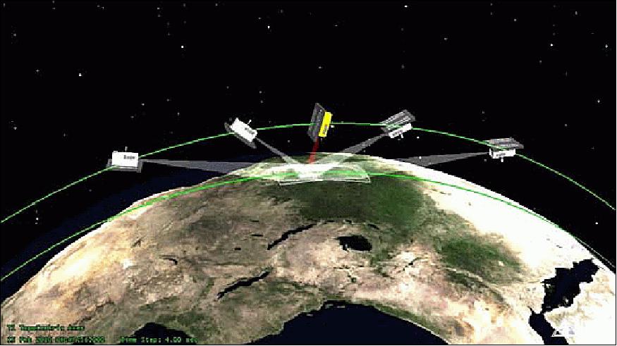
Earth observations will be done repeatedly during what are deemed as Imaging Campaigns, by pointing at ground targets at different angles with respect to zenith, thereby allowing image capture at different scattering angles. This manner of pointing is done by autonomously constructing a targeting trajectory onboard and having the ADCS regulate this trajectory, thereby pointing the imager continuously at the target of interest. This maneuver is shown in Figure 9. NEMO-AM has an in-track look capability of slightly less than 90º and an off-track look capability of 30º (in one direction). When the satellite is directly over the target at an altitude of 650 km, this imaging maneuver will produce an Earth footprint of 35 km x 95 km, with a ground sampling distance of approximately 42 m. High-speed image downlink is performed by pointing the S-band antennas at a ground station by following a targeting trajectory similar to the Imaging Campaigns. In any given day, a maximum of 2 observations and 2 high-speed downlinks are expected. When the satellite is not imaging or downlinking data, a power-generation attitude will be held by inertially pointing its +X solar array to the Sun.
Sensor Complement
The imager design of NEMO-AM is critical to precise aerosol detection. Imaging is done using a high transmissivity 150 mm f/2.8 front end lens tested by focusing to infinity. The imager then divides the incoming light into blue, red and near infrared (NIR) spectral bands. The exposure times for these three wavelengths range from 2-14 ms. The instrument also includes a "p-s" polarizing beam splitter at the spectral band output, which generates two identical images at two different polarizations. The p-polarization splits the image at 0º, whereas the s-polarization splits the image at 90º. Each polarization has a pixel density of 2444 x 888 pixels. The resulting images are focused onto the same Kodak CCD detector. The imager's optical parameters are summarized in Table 4.
Focal length | 150 mm ± 2% |
FOV (Field of View) | ± 4.46º diagonal |
Number of elements | 7 elements in 6 groups |
Resolution | MTF > 55% at 70 lp/mm |
Transmission | ≥ 89% |
Distortion | < 0.2% |
Vignetting | ≤2.5% |
Wavelength range | 400 - 1000 nm |
Anti-reflection coating | R ≤ 0.6% |
Chromatic aberration | < 5 µm |
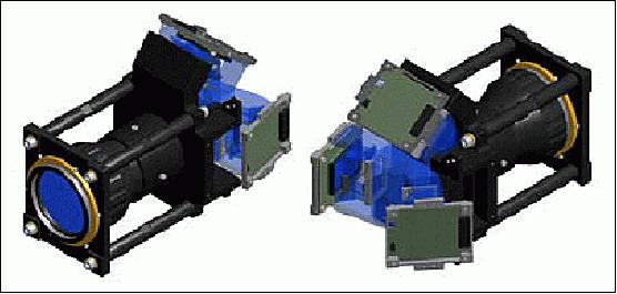
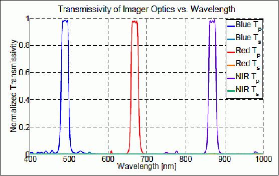
The NEMO-AM imager (radiometer) is capable of observing in the bands: 480-500 nm, 650-675 nm, and 860-880 nm (based on the channels on existing aerosol missions). The transmission performance is summarized in Figure 7. Noise contributions at the detector include photon noise, dark current noise and noise due to bias variation. The maximum signal-to-noise ratio per pixel at either the p-polarized or s-polarized regions is 158.
The NEMO-AM instrument will also include a new instrument computer system. The new instrument computer will be responsible for controlling the operations of the multiple detectors. A four-channel observation at the highest observation comprising seven observation angles will generate up to 580 MB of data. The mission is designed to cover an area of up to 80,000 km2 daily. - The UTIAS/SFL-designed optical instrument is capable of a scalable ground sampled distance of 40 m to 200 m and a ground swath of 129 km from an orbital altitude of 650 km.
Ground Segment
NEMO-AM will be operated from the MSCC (Multi-mission Spacecraft Control Center) in Bangalore, India that forms part of the ISTRAC (ISRO Telemetry, Tracking and Command Network). The communications system and operations software are based on SFL's standard approaches and are tailored to work within the existing ISTRAC environment.
Both uplink and downlink communications are in the Space Research Science S-band. The downlink transmitter on NEMO-AM is capable of variable data rates (32kbit/s to 2Mbit/s) and modulation, as set by ground command. During nominal science operations, the satellite will track the ground station with one of its body-mounted S-band patch antennas and maintain a 2Mbit/s
downlink. The same communication link is used for telemetry, control, and payload data downlink. Communications between ground software and on the radio links employ SFL's nanosatellite protocol. This is a low-overhead protocol that supports variable length packets with addressing to enable packet routing between ground terminal programs, on-board devices, and software threads in application software. The architecture was designed for closed-loop, real-time communication during contacts with the operations center to permit the ground software to ensure that there are no gaps in the uplink of the telecommands or downlink of payload data. Time-tagged data dumps to downlink only stations are also supported by the software architecture.
Spacecraft observations and data downlinks are conducted through sequences of time-tagged commands. In nominal operations, NEMO-AM will observe one or two ground targets and then downlink that observation data on subsequent passes over the Earth Station. A mission planning tool permits the operations team to schedule observation targets according to the desires of the science team while complying with constraints such as ground target illumination and platform pointing restrictions. The tool propagates the satellite's orbital ephemeris from position and velocity information recorded from the on-board GPS receiver. The outputs from these processes are time-tagged command scripts that can be uploaded to the OBCs. Typically, planning is done for up to a week in advance, depending on the accuracy of the orbit ephemeris.
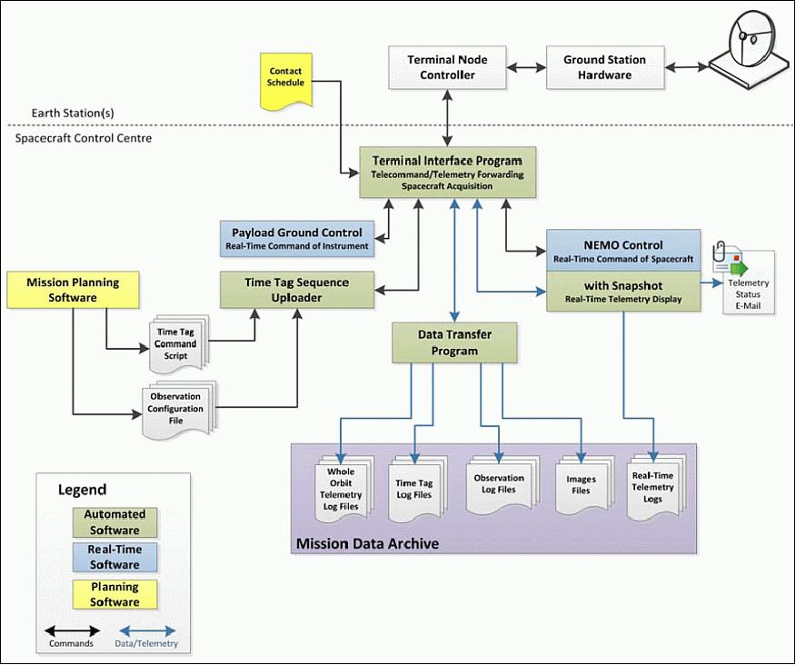
Ground software architecture: The ground software architecture for NEMO-AM is composed of a series of specialized terminal programs that communicate with the satellite through a software multiplexer application. This is shown in Figure 12. All the communication between client programs take place over TCP/IP sockets, encapsulating packets in the same protocol as used on the spacecraft. This makes it easy to accommodate new client programs for specialized data handling and data distribution. For NEMO-AM, the client programs perform automatic query and validation of real-time telemetry, downloading stored spacecraft telemetry, and command and control of the platform and its experiments.
Since the software interfaces are TCP/IP sockets, they can reside on one or more computers depending on the number of operators involved. All the software runs on standard Windows or Linux PCs. Additional software may be used and can run in other environments, provided they use the same TCP/IP interface.
SFL satellites are designed for automatic "lights-out" operation. During each contact, scheduled time-tagged command scripts are automatically uploaded, on-board bus telemetry and payload data are downloaded from the OBC and realtime telemetry is beaconed during the contacts or requested by automatic software. Incorrect telemetry results in alarm notifications to the operations team, such that operator involvement is only required for contingency situations and preparation of upcoming task schedule.
All platform telemetry, command logs, and science data are stored in files on the OBC Flash file system. The downloaded platform telemetry consists of whole-orbit data, continuously collected at a predetermined interval and, logs of uplinked commands and executed time-tagged commands. The science data consists of an Observation log with instrument telemetry, ADCS information during the image capture and up to 21 images per Imaging Campaign.
For manual operations, such as booting new software loads, the real-time control software executes scripted command sequences. The goal is to minimize repeated manual tasks, and allow the operations team to focus on planning, analysis, and new activities.
References
1) Freddy M. Pranajaya, Robert E. Zee, "The NEMO Bus : A Third Generation High-Performance Nanosatellite for Earth Monitoring and Observation," Proceedings of the Symposium on Small Satellite Systems and Services (4S), Funchal, Madeira, Portugal, May 31-June 4, 2010
2) Freddy M. Pranajaya,, "Operational and Upcoming Nanosatellite and Microsatellite Missions," APRSAF-16 (Asia-Pacific Regional Space Agency Forum), Bangkok, Thailand, January 26-29, 2010, URL: http://www.aprsaf.org/data/aprsaf16_data
/Day-1_seu_1545_APRSAF-16_SEU-WG_Pranajaya_Microsatellite_and_Nanosatellite_Activities.pdf
3) F. M. Pranajaya, R. E. Zee, "The NEMO Bus: A Third Generation High-Performance Nanosatellite for Earth Monitoring and Observation," Proceedings of the 24th Annual AIAA/USU Conference on Small Satellites, Logan, UT, USA, Aug. 9-12, 2010, SSC10-VI-8, URL: https://utias-sfl.net/wp-content/uploads/SSC10-VI-8.pdf
4) F. M. Pranajaya, R. E. Zee, "The NEMO Bus: A Third Generation High-Performance Nanosatellite for Earth Monitoring and Observation," Proceedings of ASTRO 2010, 15th CASI (Canadian Aeronautics and Space Institute) Conference, Toronto, Canada, May 4-6, 2010
5) Freddy M. Pranajaya, Simon C. O. Grocott, Robert E. Zee, "The NEMO Bus: An Advanced Nanosatellite Bus for Earth Monitoring and Observation," Proceedings of the 28th ISTS (International Symposium on Space Technology and Science), Okinawa, Japan, June 5-12, 2011, paper: 2011-n-02
6) F. M. Pranajaya, S. C. O. Grocott, R. E. Zee, "The NEMO Bus: Nanosatellite for Earth Monitoring and Observation," 8th IAA (International Academy of Astronautics) Symposium on Small Satellites for Earth Observation, Berlin, Germany, April 4-8, 2011; URL of presentation, IAA-B8-1401, http://media.dlr.de:8080/erez4/erez?cmd=get&src=os/IAA/archiv8
/Presentations/IAA-B8-1401_Pranajaya_NEMO%20Bus.pdf
7) S. C. O. Grocott, N. S. Ibrahim, D. Diaconu, M. Dwyer, J. Elliott, D. Kekez, I. Majid, F. Pranajaya, M. Stan, R. E. Zee, "NEMO‐AM: High Fidelity Autonomous Nanosatellite for Earth Observation and Aerosol Monitoring," Proceedings of the 4S (Small Satellites Systems and Services) Symposium, Port Petro, Majorca Island, Spain, May 26-30, 2014
8) Information provided by Robert E. Zee, Director of SFL, Toronto, Canada.
The information compiled and edited in this article was provided by Herbert J. Kramer from his documentation of: "Observation of the Earth and Its Environment: Survey of Missions and Sensors" (Springer Verlag) as well as many other sources after the publication of the 4th edition in 2002. - Comments and corrections to this article are always welcome for further updates (eoportal@symbios.space).
Overview Spacecraft Launch Sensor Complement Ground Segment References Back to top