MTSAT (Multifunction Transport Satellite)
EO
Atmosphere
Ocean
Cloud type, amount and cloud top temperature
Quick facts
Overview
| Mission type | EO |
| Agency | JCAB, JMA |
| Mission status | Mission complete |
| Launch date | 15 Nov 1999 |
| End of life date | 31 Dec 2018 |
| Measurement domain | Atmosphere, Ocean |
| Measurement category | Cloud type, amount and cloud top temperature, Liquid water and precipitation rate, Surface temperature (ocean), Atmospheric Humidity Fields, Atmospheric Winds |
| Measurement detailed | Cloud top height, Cloud type, Cloud imagery, Sea surface temperature, Precipitation index (daily cumulative), Wind profile (horizontal), Water vapour imagery |
| Instruments | Imager, JAMI, MTSAT DCS, MTSAT Comms |
| Instrument type | Imaging multi-spectral radiometers (vis/IR), Communications, Data collection |
| CEOS EO Handbook | See MTSAT (Multifunction Transport Satellite) summary |
MTSAT (Multifunction Transport Satellite)
MTSAT is a Japanese geostationary dual-function satellite program, procured by JCAB (Japan Civil Aviation Bureau) and JMA (Japan Meteorological Agency), and funded by the Japanese Ministry of Land, Infrastructure and Transport (MLIT), with the following overall objectives: 1) 2) 3) 4)
1) Aeronautical mission. To augment the air-traffic control services through enhanced communication and position information to Japan's (and the Asia-Pacific region) air traffic capability. The objective is to provide a satellite-based service, referred to as CNS/ATM (Communication, Navigation, Surveillance / Air Traffic Management) by utilizing the GNSS and augmentation services for satellite navigation. The CNS/ATM concept makes use of the ADS (Automatic Dependent Surveillance) function which automatically reports the current aircraft position measured by GNSS to ATC (Air Traffic Control Center).
2) Meteorological mission. MTSAT is a successor program to the GMS (Geostationary Meteorological Satellite) series - representing the next-generation weather-watch satellite series. The advanced meteorological observation capabilities include data collection services for a large user community.
Background
In the mission planning phase of the program (early 1990s), the two agencies, JMA and JCAB - recognized an opportunity to satisfy their operational spaceborne mission requirements of two different services (aeronautical communications and navigation, and meteorological observations- both from GEO) in a most efficient manner by combining their missions onto a single satellite bus. The ICAO (International Civil Aviation Organization) initiated and approved the new system in 1991, designating it the CNS/ATM system, for Communications, Navigation, Surveillance and Air Traffic Management for the global Air Navigation System.
When the two agencies decided on this cooperative approach to satisfy their two missions, both were entities within the Japanese Ministry of Transport, which was reorganized in 2000 into the Ministry of Land, Infrastructure and Transport (MLIT), effective as of Jan. 1, 2001. Thus, the space segment was named "Multifunction Transport Satellite," abbreviated to "MTSAT." 5)
MTSAT-1 was launched on Nov. 15, 1999 with an H-2 vehicle from the Tanegashima Space Center, Japan. However, a launch failure of the H-2 vehicle (No 8) occurred due to an abnormal burning of the first stage resulting in a destruction of the entire vehicle. - In March 2000, Space Systems/Loral (SS/L) of Palo Alto, CA, received a follow-on contract from Japan's Ministry of Transport to build a replacement satellite, MTSAT-1R. In addition, Japan's Ministry of Transport ordered MTSAT-2 from MELCO (Mitsubishi Electric Company) of Tokyo, Japan.
MTSAT-1 | Launch Nov. 15, 1999 (launch failure of H2 launch vehicle) |
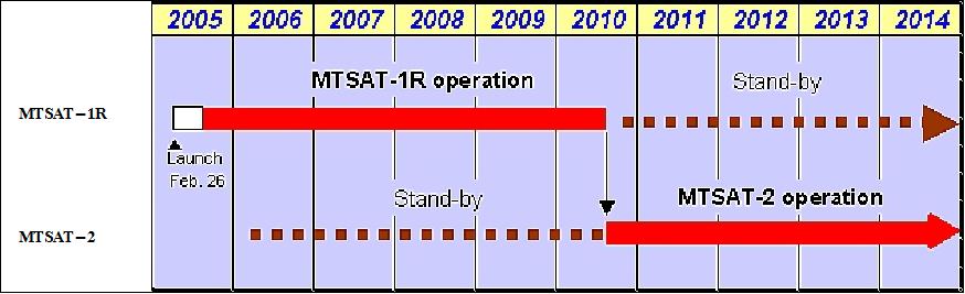
MTSAT-1R | - Launch Feb. 26, 2005 (launch on H2A launch vehicle from TNSC into GTO) |
MTSAT-2 | - Launch Feb. 18, 2006 (launch on H2A launch vehicle from TNSC into GTO) - The MTSAT-2 spacecraft became prime on July 1, 2010 for meteorological services. |
MTSAT-1R (Multifunction Transport Satellite-1 Replacement), Himawari-6
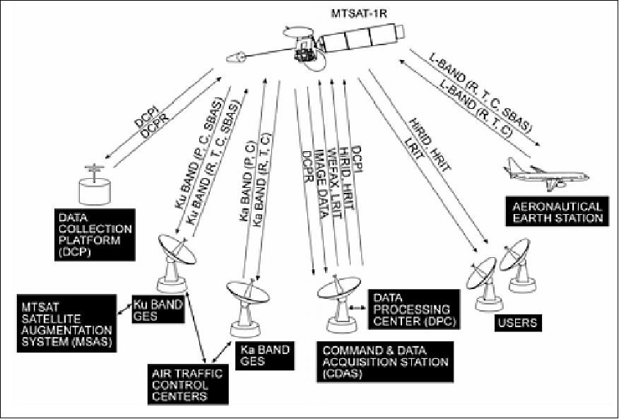
There are three components of the overall system architecture:
1) The space segment consists of the MTSAT satellites (-1R and -2) and the signals of the GPS constellation.
The MTSAT series uses the services of GPS satellites in order to provide (supplementary) enhanced aeronautical communication, air navigation, GPS augmentation and differential correction services. Several ground stations complement the space segment (There are two JCAB stations and a separate JMA ground station. The JMA station includes satellite monitoring and control functions, communications functions and image processing and dissemination functions.
2) The airborne (or aeronautical) segment (the avionics and communication equipment flown on aircraft operating with the support of the MTSAT system)
3) The ground segment (the satellite operations and payload operations centers that control the satellite and process and link mission data with the satellite).
Spacecraft
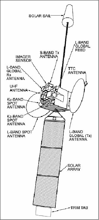
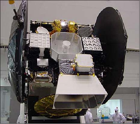
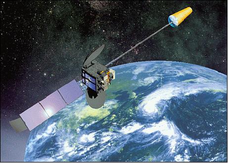
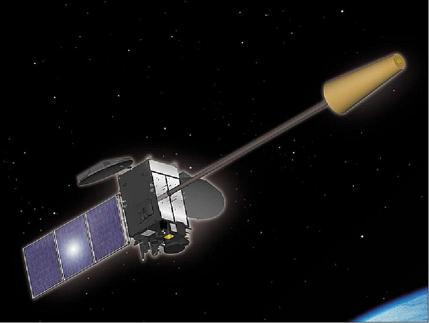
The MTSAT-1R spacecraft bus, built by SS/L (Space Systems/Loral), uses the three-axis, stabilized FS 1300 platform of SS/L adapted for the meteorological observation mission.. The overall S/C configuration consists of a box-like main structure (2.4 m x 2.6 m x 2.6 m in size), a single-wing solar array mounted on the south face of the structure, a solar sail in the north direction, and two large L-band antennas mounted on the east and west faces. The overall length of the deployed spacecraft is 33.05 m. 7) 8)
The ADCS (Attitude Determination and Control Subsystem) uses a bias momentum method to stabilize the S/C. Attitude is measured by an Earth sensor. A boom-mounted solar sail in the opposite direction of the solar array, serves as attitude actuator by providing a counterbalance to the solar pressure. A trim tab is mounted on the outer edge of the solar array offering a control mechanism. The solar array, consisting of three panels (each 2.4 m x 2.6 m), uses GaAs cells and continuously tracks the sun in order to maximize power output. Power of 2.7 kW (EOL) is provided. The NiCd battery has 22 cells for eclipse phase power. The bi-propellant propulsion subsystem uses 12 thrusters (22 N each) for attitude control. In addition a thruster of 490 N provides control for initial orbit raising. The S/C mass at launch is 2,900 kg.
Aeronautical Payload: Frequency bands and EIRP (Effective Isotropic Radiated Power) | L-band 6 spot beams: 43 dBW, (1.5/1.6 GHz) |
Meteorological Payload: Frequency bands and EIRP | S-band global: 55 dBm |
TT&C (Telemetry Tracking & Command): Frequency bands and EIRP | USB (Unified S-band): 27.5 dBm (USB is used for orbit raising and contingency operations via the omni-directional telemetry and command antenna) |
Spacecraft mass | About 2,900 kg of launch mass, 1600 kg of dry mass |
Length of S/C, S/C power | 33 m (total deployed length), 3 kW |
Spacecraft design life | 10 years for aeronautical mission |
Orbit: Geostationary orbit (equator) located at 140º eastern longitude.
Launch
A launch of MTSAT-1R into GTO took place on Feb. 26, 2005 on a H-2A F7 launch vehicle of JAXA from the Tanegashima Space Center (TNSC), Japan. 9)
JAXA carried out extensive analysis and inspections following the launch failure of MTSAT in Nov. 2003 [this involved the JAXA launch of the two Japanese military reconnaissance spacecraft IGS-2a and -2b (Information Gathering Satellite-2a and -2b - with optical and SAR payloads), on an H2A vehicle from TNSC], and supervising launch operations and safety assurance as commissioned by RSC (Rocket System Cooperation). RSC performed the launch operations and supervision of all stages of launch vehicle manufacturing. Mitsubishi Heavy Industries, Ltd manufactured the first and second stage systems and solid strap-on boosters for the H-IIA launch vehicle.
Aeronautical Mission (JCAB)
The objective is to use a spaceborne augmentation system to improve the management of Japan's civil air traffic. Faced with the constant growth in air transport in South-East Asia and the special geographical factors in this region, the Japanese Ministry of Transport represented by the Japanese Civil Aviation Bureau (JCAB) has opted for a full-scale implementation of a satellite-based Communication, Navigation, Surveillance/Air Traffic Management (CNS/ATM) concept. This concept is based on the use of a geostationary satellite in order to overcome the limits imposed by traditional terrestrial navigation aids. 10) 11)
The main features of the aeronautical payload include:
- A DTP (Digital Transparent Processor) to multiplex and separate, route, and combine the channels, as well as to provide frequency agility and gain control
- An adaptive MPA (Multiport Amplifier) with a six-beam antenna to provide maximum flexibility to respond to changing communications traffic distribution
- Steerable antennas to permit versatility in selecting the orbital location.
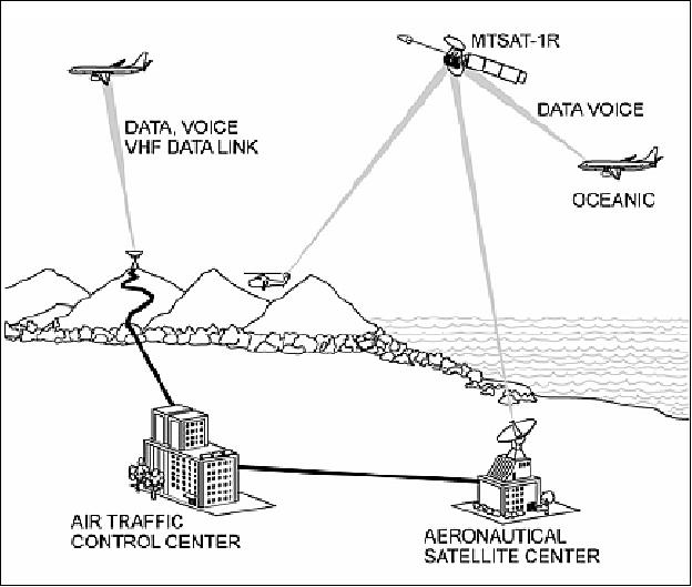
The MTSAT aeronautical mission provides three basic functions for its area of coverage: communications, navigation, and surveillance.
1) Communications
Voice/data interchange between aircraft and control tower. Air traffic communications use the L-band and the AMSS (Aeronautical Mobile Satellite Service) protocol which is specific to mobile telecommunications. Links between the Earth segment and satellite segment use the Ku-band and Ka-band.
MTSAT significantly improves the quality and capacity of voice and data communications to/from aircraft compared to conventional systems. In addition, it permits direct communication between any two aircraft in a region as well as to ground control centers.
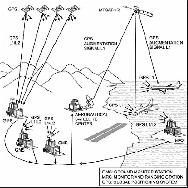
2) Navigation by satellite - referred to as SBAS (Satellite-Based Augmentation System)
MTSAT serves as a geostationary wide-area augmentation system for all GPS signals in its large area of coverage by transmitting:
• GPS-like signals (ranging function)
• GPS health and integrity conditions obtained by ground monitoring stations (GMS)
• Ranging errors (differential correction function) - these are the conventional DGPS services
The GPS wide-area signal augmentation provided by MTSAT makes all regional navigation seamless, very reliable, available, more accurate, and continuous. This service is referred to as MSAS (MTSAT Satellite-based Augmentation System). The MSAS architecture is composed of the following ground-based elements: MRS (Monitor and Ranging Stations), GMS (Ground Monitor Stations), and MCS (Master Control Stations). In addition, there are two GES (Ground Earth Station) in the system, namely the Kobe Aeronautical Satellite Center and the Hitachi-Ota Aeronautical Center), providing operational support.
MSAS information on the real-time condition of the GPS constellation is transmitted to each aircraft via the integrity function of MSAS, while the differential correction function provides ranging error data to each aircraft. MSAS uses advanced technologies such as satellite orbit ranging, and ionospheric and tropospheric delay estimation assumption to ensure the reliability of these functions. 12)
MTSAT-1R navigation payload SBAS: The navigation payload has been built by Alcatel Space of France under subcontract to SS/L.
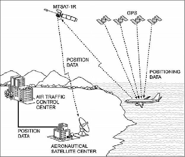
3) Air traffic surveillance
MTSAT-1R is the key element of the Japanese GNSS (Global Navigation Surveillance System). The S/C features an ADS (Automatic Dependent Surveillance) relay service with the objective to transmit accurate positioning data for aircraft obtained by GPS (or GLONASS) to achieve higher-quality control. The data is transmitted at regular intervals to ground control centers via MSAS. ADS enables positioning information of aircraft to be displayed on control consoles, permitting ground control personnel to verify the aircraft position anywhere along its flight path. Such data include aircraft identification, four-dimensional position, and supplementary data to the air traffic control facility. The links between the ground and the satellite use the Ku-band and Ka-band; links between the aircraft and the satellite use the L-band.
The overall design of the "aeronautical mission" with its three basic functions provides redundancies. However, these redundancies are deliberately designed into the space segment as well as into the ground segment to provide an operational system that satisfies every aspect of the ICAO (International Civil Aviation Organization) requirements in terms of reliability, availability, and accuracy.
Meteorological Mission (JMA)
The Meteorological Mission of MTSAT succeeds the observational function of the current GMS (Geostationary Meteorological Satellite) series. GMS-5 (with VISSR), the latest in the series, was launched March 18, 1995 has exceeded its design life already in 2000. 13) 14)
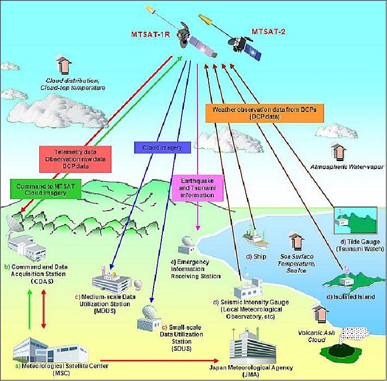
The MTSAT spacecraft takes over three major meteorological mission functions from the GMS series, namely a) acquisition of Earth imagery, b) dissemination of image data, and c) collection of meteorological data from the ground segment using the DCP (Data Collection Platform) system. The data collection function of MTSAT satellites is as same as that of GMS-5.
The MSC (Meteorological Satellite Center) of JMA (Japan Meteorological Agency) is responsible for the operation of the MTSAT meteorological mission. MSC activities also include the development and distribution of MTSAT products such as hourly AMVs (Atmospheric Motion Vectors) and Clear Sky Radiance (CSR) for use in Numerical Weather Prediction (NWP), and also the dust detection product for atmospheric environment monitoring.
Status of Meteorological Mission
• On July 7, 2015, the Himawari-8 spacecraft began its operational phase, replacing the previous MTSAT-2 operational satellite (now in standby). 15)
• 2015 status of the JMA (Japan Meteorological Agency) program. 16)
- Himawari-8 was successfully launched on 7 October 2014.
- JMA plans to start its operation on 7 July 2015 as a replacement for MTSAT-2.
- Himawari-8 will observe the East Asia and Western Pacific regions for a period of 15 years with Himawari-9.
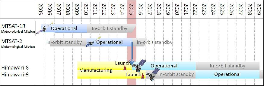
• February 2015: The MTSAT-2 spacecraft (Himawari-7, located at 145ºE) and its payload are operating nominally in 2015, with MTSAT-1R in standby. 17) 18)
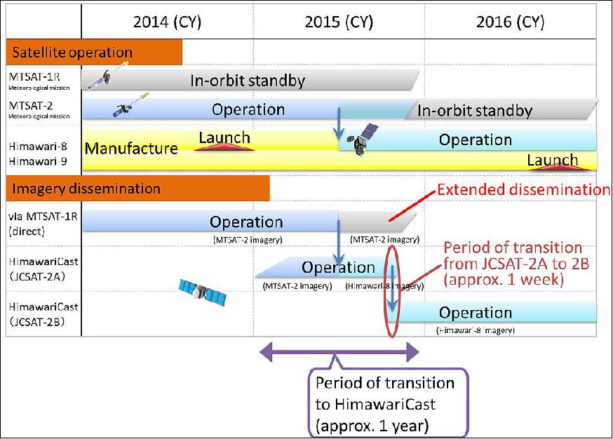
• MTSAT-2 imagery dissemination via the HimawariCast service began at 03:00 UTC on 29 January 2015. 19)
- MTSAT-2 imagery is currently provided directly via MTSAT-1R through the L-band frequency HRIT (High-Rate Information Transmission) and LRIT (Low-Rate Information Transmission) services. JMA will terminate these services in around November 2015. As a replacement of these services, JMA started the HimawariCast service which disseminates primary sets of imagery via a communication satellite from January 2015 onwards.
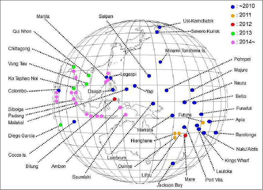
• May 2014: The MTSAT-2 DCS (Data Collection System) plays a very important role in disaster prevention services in the Asia and Pacific regions. 20)
- In recent years, the number of tidal/tsunami stations using MTSAT-DCS has rapidly increased. In addition, the high-frequent collection (6 minutes interval) is implemented.
• The MTSAT-2 spacecraft (Himawari-7) and its payload are operating nominally in 2014, with MTSAT-1R in standby (since 2010); there are periodical backup of MTSat-2 during equinox season (Ref. 22). - According to the Satellite Program Division of JMA, MTSAT-2 will finish its meteorological mission in 2017. 21)
• The MTSAT-2 spacecraft is providing meteorological observations in 2013 (with MTSAT-1R in standby). During the equinox season in the spring of 2013, some communication outages are expected (Ref. 22).
• The MTSAT-2 spacecraft is providing meteorological observations in 2012 (with MTSAT-1R in standby, periodical backup of MTSat-2 during equinox season. 22)
• The MTSAT-2 spacecraft is providing meteorological observations in 2011 (with MTSAT-1R in standby). 23)
• In the period Oct. 22 to Dec. 22, 2010, meteorological observations were provided by the MTSAT-1R spacecraft for reasons of maintenance of the MTSAT-2 ground system. 24)
• On July 1, 2010, JMA switched the meteorological observation services from MTSAT-1R to the MTSAT-2 spacecraft. This action put the MTSAT-1R spacecraft into meteorological standby. 25)
- In the event of anomalies with MTSAT-2, or the need for maintenance of the satellite or its ground system, MTSAT-1R will be brought back into operation after the switchover.
- MTSAT-1R will continue to operate the DCS (Data Collection System) to collect environmental data from DCPs (Data Collection Platforms) in the ground segment.
• MTSAT-1R is operating nominally in the spring of 2010. MTSAT-2 is still on standby (Ref. 1). 26)
• After calibration and tuning of the meteorological imager and associated ground processing equipment, the meteorological mission began full operation on June 28, 2005, providing services to Japan, eastern Asia and the western Pacific. 27)
• As of mid-2006, the process for the automatic detection of landmarks and Earth edges has been working operationally for many months on MTSAT-1R. The ability to use these data as the basis to determine the satellite orbit and attitude has also been demonstrated. Extensive modelling and analysis work (using images for which the satellite orbit and attitude was known precisely) has shown that good correlation with the true orbit and attitude can be achieved.
Sensor Complement of the Meteorological Mission
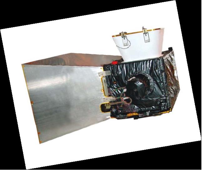
JAMI (Japanese Advanced Meteorological Imager)
The overall objective of the meteorological mission is to provide an improved functionality and continuous service of meteorological observables (timely, high-quality, full-disk multispectral imagery for operational weather needs) for Japan and for the countries in the area of MTSAT coverage (East Asia, and Australia). The JAMI instrument has been designed and developed by Raytheon SBRS (Santa Barbara Remote Sensing) of Goleta, CA under contract to Space Systems/Loral. The JAMI performance enhancements include [compared to those of the S-VISSR (Stretched - Visible and Infrared Spin-Scan Radiometer) instrument flown on GMS-5]: 28) 29) 30) 31) 32) 33) 34)
• Coverage of the 0.55 µm to 12.5 µm spectral region using four infrared (IR) bands and one solar reflective band (VNIR)
• Large-format arrays enable faster full disk coverage rate with slower scan rate. The benefits of slower scan rate include longer dwell times, higher detector resolution, and a longer scanner life
• Full disk coverage with calibration scans in 24 minutes.
• Onboard calibration system for all bands
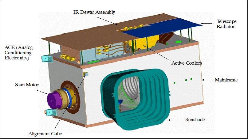
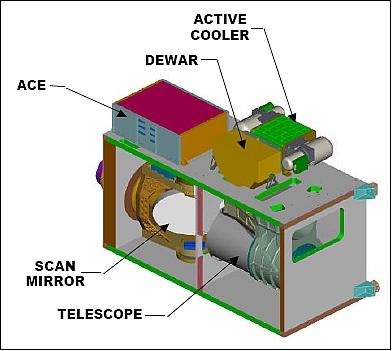
The instrument consists of the following elements: Mainframe, Scanner, Telescope, Cryocooler, ACE, FPAs (Focal Plane Assemblies), Blackbody, and Albedo Monitor. JAMI's design is based on advanced imager technologies that have already been space-qualified and flown in Raytheon-built hardware:
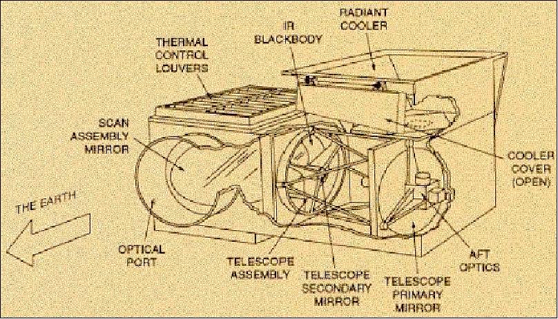
• Uses a two-axis gimbaled scan mirror with qualified optical (off-axis TMA telescope) and mechanical elements which have been derived from many Raytheon programs with demanding requirements for spaceflight operation including: MODIS, GOES/GMS (Imager/VISSR), Landsat (TM, ETM+), and TRMM/VIRS. The simple optical design uses an off-axis focal telescope with two focal planes and infrared bands integrated into a single sensor chip assembly. The scan function for this imager is completely flexible; the scanner can be commanded to point outside the full frame scan area and provide views of onboard blackbody and albedo monitoring sources.
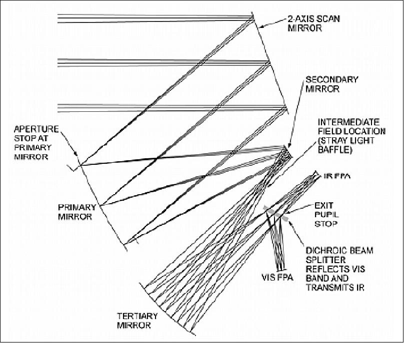
• The TMA off-axis reflective telescope collects and focuses input radiance onto two focal planes which spatially sample Earth at the Nyquist rate for 4 km IR ground resolution and 1 km visible ground resolution. Detector arrays in both focal planes are completely redundant and contain monolithic detector arrays that use materials optimized to their spectral regions. Two columns of detectors are fabricated for each infrared band. This provides a primary and an alternative detector element, individually selectable during focal plane subsystem integration and testing to improve producibility of 100% operable arrays. The double focal plane offers significant advantages with respect to other design approaches. These include separation of visible and infrared arrays to improve cooling performance of the infrared arrays and a much simpler and easier to build optical layout than current operational imagers (heritage of ALI design on EO-1 mission).
• A beam splitter separates the incident spectrum into visible and IR channels. IR optical filters further separate the IR radiation into four IR bands.
• Use of active coolers in GEO derived from Raytheon expertise in DoD programs.
• Photovoltaic HgCdTe focal plane arrays that incorporate qualified designs [the infrared bands are contained in two sensor chip assemblies (SCAs) with direct flight experience in TRMM/VIRS, Multispectral Thermal Imager (MTI), and MODIS]. Active cooling of the focal plane detector arrays is provided.
• Processing hardware and software was derived from MODIS and incorporates processing algorithms which have already been proven on Landsat, Hubble Space Telescope, and many other spaceflight programs
• Equipped with an onboard blackbody calibrator that has already been qualified and spaceflight proven on TRMM/ VIRS and MODIS with four years of on-orbit operation. Calibration is provided through several mechanisms: space view and V-groove blackbody source for the infrared bands, and a reflective solar albedo monitor for the visible band.
• Improved data quality with Nyquist spatial frequency sampling of an Earth scene. Nyquist spatial sampling ensures radiometric accuracy of resampled and registered data, provides capability to implement landmark collection mode to improve nighttime IR landmarking and better determine non-static co-registration errors. JAMI transmits 4 km infrared data in normal operating modes and can provide 1.0. km visible band data (requirements called for 4 km and 1 km resolutions, respectively).
Spectral bands | VNIR: 0.55 - 0.90 µm (cloud cover, solar reflective band) |
Telescope aperture, focal length | 311 mm diameter, 894.8 mm, f/2.7, IFOV = 17.5 µrad |
Optical transmittance | ≥ 0.7 |
MTF (visible) | 0.60 (at 20000 rad-1 at digitizer) |
FOV | 0.269º per swath, (Telescope FOV is > 0.3º x 1º) |
Image frame | 21.4º (N-S) by 23.6º (E-W) |
Scanner, scan rate | Two-axis scan system, 1.6º/s |
Detector type | Monolithic silicon (visible), Photovoltaic HgCdTe (all IR regions) |
FPA technical approach | For each IR band an active staggered array of 84 HgCdTe detectors (50x50 µm each) |
Detector IFOV | 14 x 14 µrad for VNIR, 56 x 56 µrad for all IR channels |
Effective dwell time (1 km GSD) | 1 ms |
Full disk coverage time | ≤ 21 minutes |
Data quantization | 10 bit (all channels) |
Ground Sample Distance (GSD) | 1.0 km in VNIR (Visible Near Infrared), |
Calibration accuracy (1 observation) | 2.5% (visible), 0.08-0.16 K (IR at 300 K), 0.08-0.10 K (IR at 220 K) |
Data rate | 2.7 Mbit/s (max) |
Instrument mass, power | 163.7 kg (including 16.7 kg of interconnecting harness), 169 W |
Spectral band | Temperature/albedo resolution | Operating temperature |
VNIR (Visible Near Infrared) | at 100% albedo ≥ 84 | 300 K |
MWIR1 (Mid Wave Infrared 1) | at 300 K ≤ 0.18 K | 75 K |
MWIR2 (Mid Wave Infrared 2) | at 300 K ≤ 0.18 K | 75 K |
TIR1 (Thermal Infrared 1) | at 300 K ≤ 0.15 K | 75 K |
TIR2 (Thermal Infrared 2) | at 300 K ≤ 0.18 K | 75 K |
The two-axis gimbaled mirror scan system simultaneously sweeps a 168 km, predominantly N/S swath along a predominantly E/W path. The scan profile used is called a Tapered Elevation Scan (TES) that couples the N/S and E/W scan coordinates to correct for field rotation and maintain IR band-to-band registration.
JAMI uses long linear detector arrays for each wavelength band. The visible array is composed of 336 detectors each having a 14 µrad IFOV (Instantaneous Field of View), corresponding to a 0.5 km footprint at nadir. The IR arrays are composed of 84 detector elements in each spectral range with a 56 µrad IFOV providing a 2 km footprint at nadir.
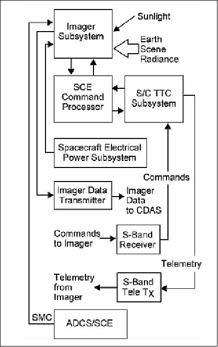
SMC (Spacecraft Motion Compensation): The motion of the JAMI scan mirror causes a small but well-defined disturbance to the spacecraft attitude that is modeled in the ADCS as one component of SMC. Compensation signals to counteract predictable spacecraft attitude and structural/thermal effects on Imager pointing can be programmed. These effects are determined through image post-processing on the ground, and corrective coefficients are computed and uploaded to the ADCS, which uses them to generate the second component of the SMC signal. The third component can be generated by the ADCS based on information available on-board the spacecraft from the telemetry system.
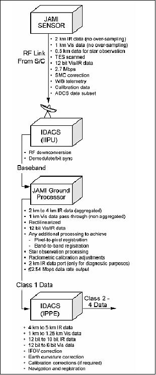
In the ground station, the digital imager data is routed through the JPG (JAMI Ground Processor) system. The JPG resamples and calibrates the raw imager data. Subsequent processing generates the fundamental image products. The JPG calibrates the raw data based on information embedded in the data stream and resamples the IR data to convert the downlinked 2 km data to 4 km IR data. The 0.5 km visible data is aggregated on board the satellite to produce the 1 km data, which is downlinked.
JAMI provides the following imaging modes:
- Earth observation
- Star observation for precision spacecraft attitude determination
- Infrared calibration
- Visible stability confirmation.
The position and size of an area scan in the imager's field of regard (FOR) is controlled either by preset observation schedules for routine Earth imaging or by ground commands. The instrument is capable of full Earth imagery, sector imagery that contains the edges of Earth, and various sizes of area scans totally enclosed within the Earth scene. The vignette-free FOR of the imager is 21.4º North/South (N/S) by 23.6º East/West (E/W).
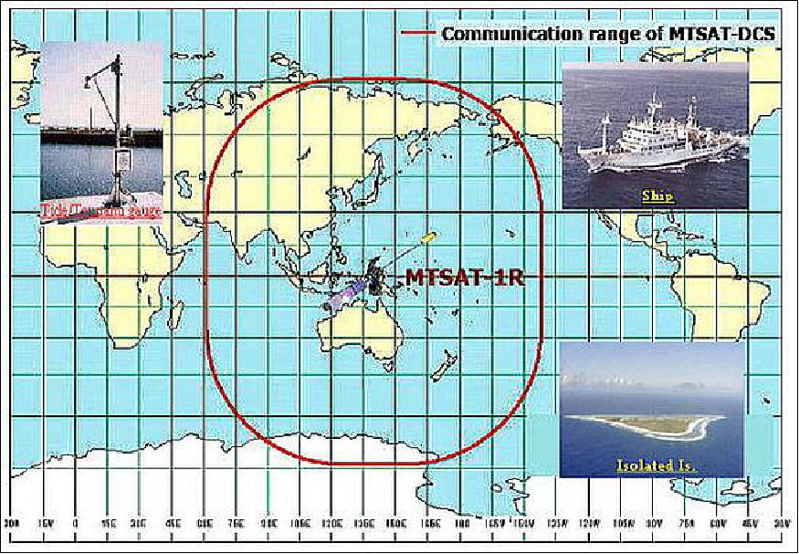
DCS (Data Collection System)
The MTSAT series supports the collection of environmental data in its ground segment with a corresponding on-board DCS (Data Collection System), in the same manner as provided by the GMS series. The ground segment platforms are referred to as DCP (Data Collection Platform) which are automated remote weather stations. 35) 36)
The DCS is part of IDCS (International DCS) coordinated with other meteorological satellite operators. The DCP data are collected through the MTSAT spacecraft and rectified to the WMO codes at MSC and distributed to users through GTS.
• DCPI (DCP Interrogate). The DCPI channel relays the interrogation commands from the CDAS at S-band through the S-band channelizer amplifier and UHF transmitter to the data collection platform.
• DCPR (DCP Report). The DCPR channel relays data from the DCPs through the UHF transponder, which outputs an S-band signal.
There are two types of DCPs: 1) Self-timed DCPs which transmit observation data automatically on scheduled times. 2) The interrogation DCPs transmit observation data by an interrogation command from the MSC.
The interrogate command is uplinked to the satellite via CDAS in S-band, and then repeated by the satellite in UHF. The UHF signal is broadcast to DCPs in a global pattern using a dipole antenna. The same antenna receives the uplinked UHF signal from the DCPs. The DCP signal is retransmitted to CDAS via the same S-band downlink that carries the imager data, from where it is sent by terrestrial microwave link to MSC.
In addition, the DCS is used to transmit Tsunami Earthquake emergency information and seismic intensity data.
Communication of Meteorological Data
Spacecraft imagery obtained is transmitted to a ground station, referred to as CDAS (Command and Data Acquisition Station) where some information, such as calibration tables, are added.
The observational data are transmitted in S-band (downlink frequency: 2026-2035 MHz, uplink frequency: 1677-1695 MHz). An S-band slot array antenna is used for downlink transmissions while an S-band horn antenna is employed for uplink reception. The S-band downlink carries the raw imager data, the image products that are being retransmitted after generation by CDAS, the data received from the DCP (Data Collection Platforms), and spacecraft telemetry data.
The raw imagery from JAMI is pre-processed to convert the data to properly calibrated temperature and albedo values (for infrared and visible bands, respectively). The raw images are remapped to an Earth-fixed frame of reference and map projection, thereby eliminating the effects of the satellite's orbit and attitude which are present in the original raw image data. The resulting corrected images are disseminated to users throughout Asia and Australasia via a relay onboard the MTSAT satellite.
In order to apply the geometric correction, it is necessary to have an accurate and timely determination of the satellite orbit and attitude. This is achieved through the automatic detection of landmarks and Earth edges in each Earth observation. These are used together with ranging data (and star data for MTSAT-1R) to determine the satellite orbit and attitude, as illustrated in Figure 22, which shows the main processing stages involved, and the relationships between these various stages. The ranging information is obtained, as part of the ground processing, from accurate timing of the duration of the signal path in the transmitted HRIT product, relayed via the MTSAT satellite to the users. - The IDACS (Image Data Acquisition and Control System) of JMA is providing the pre-processing functions involving both the ingestion of the raw data from the satellite, and the construction of radiometrically corrected and geometrically corrected images from these data. 37)
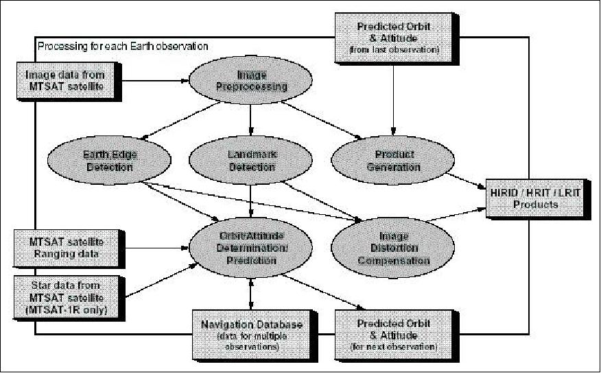
Figure 22: Pre-processing stages of imagery through automated landmark detection (image credit: LogicaCMG)
MTSAT User Data Dissemination Services
MTSAT broadcasts processed data and imagery to users throughout the Asia-Pacific region, including airports, weather forecasting agencies and ships at sea. 38)
1) LRIT (Low Rate Information Transmission) products, quite similar to the EUMETSAT products, are generated and distributed. LRIT is a new data dissemination service for SDUS (Small-scale Data Utilization Station) users. The SDUS and WEFAX services are available in the same frequency band according to a time-sharing dissemination schedule. The LRIT data format is a digital format standardized by CGMS (Coordination Group for Meteorological Satellites) composed of the meteorological satellite operators, whereas WEFAX is an analog transmission. It enables the users to extract quantitative meteorological parameters describing state of the atmosphere and surface of the earth and provides much wider applications with satellite data.
2) HiRID (High Resolution Imager Data) products are available to MDUS (Medium-scale Data Utilization Station) users. Starting in 2005, a HRIT (High Rate Information Transmission) service is being introduced as a successor to HiRID. In the period from 2005 to 2008, both HRIT and HiRID are available in the same frequency according to a time-sharing dissemination schedule.
Note: The HiRID and WEFAX services will be discontinued on March 12, 2008. 39)
Channel | Receive frequency (MHz) | LO frequency (MHz) | Transmit frequency (MHz) | Downlink signal bandwidth | |
1st LO | 2nd LO | ||||
Imager data | - | N/A | N/A | 1677.0 | < 10 MHz |
HRIT HiRID | 2029.1 | 1900 | 1558 | 1687.1 | < 6 MHz |
LRIT/WEFAX | 2033.0 | 1900 | 1558 | 1691.0 | < 1.2 MHz |
DCPI1 | 2034.925 | 1900 | 333.95 | 468.875 | 6 kHz |
DCPI2 | 2034.933 | 1900 | 333.95 | 468.883 | 6 kHz |
DCPI3 | 2034.974 | 1900 | 333.95 | 468.924 | 6 kHz |
S-band TLM | - | N/A | N/A | 1694.0 | < 0.4 MHz |
DCPR | 40.2.2 | 1292.3 | N/A | 1694.5 | < 0.4 MHz |
Spacecraft | MTSAT-1R | GOES-9 | GMS-5 |
Imager | JAMI | Imager | VISSR |
Operations period | June 28, 2005 | May 22, 2004 to present | June 13, 1995 to May 22, 2004 |
GEO location | 140º E | 155º E | 140º E |
Raw data format | HRIT | GVAR | VISSR |
Number of channels | 5 | 5 | 4 |
Spatial resolution at nadir | VNIR = 0.5 km | VIS = 1 km | VIS = 1.25 km |
Data quantization | 12 bit all channels | 10 bit all channels | VIS: 6 bit; IR: 8 bit |
References
1) http://www.jma.go.jp/jma/jma-eng/satellite/
2) http://www.jma.go.jp/jma/jma-eng/satellite/Basic_Information/Basic_Information.html
3) MTSAT brochure, JMA, Feb. 2005, URL: http://www.jma.go.jp/jma/jma-eng/satellite/Basic_Information/brochure.pdf
4) A press kit "Launch and Tracking & Control of the Multifunctional Transport Satellite (MTSAT) was provided by T. Moriyama of NASDA
5) K. Faller, "MTSAT-1R: A Multifunctional Satellite for Japan and the Asia-Pacific Region," Proceedings of the 56th IAC 2005, Fukuoda, Japan, Oct. 17-21, 2005, IAC-05-B3.2.04
6) http://www.jma.go.jp/jma/jma-eng/satellite/about_mt/2.Meteorological_payload.html
7) Information provided by Ken Faller of Space Systems/Loral
8) Yutaka Oikawa, Kosuke Kato, "Flight Inspection for MTSAT," Toulouse, France, June 12-16, 2006, URL: http://icasc.co/sites/faa/uploads/documents/resources/14th_int_flight_inspection
_symposium/Flight_Inspection_for_MTSAT.pdf
9) "Loral-Built MTSAT-1R Multi-Functional Satellite Succesfully Launched," Feb. 26, 2005, URL: http://www.ssloral.com/html/pressreleases/pr20050228.html
10) http://www.eurocontrol.int/nexsat/gallery/content/public/Steering%20Group
/Meeting9/DAY2/MTSAT%20Update.pdf
11) http://www.mlit.go.jp/koku/english/06_airtraffic/index.html
12) "Overview of MSAS,", URL: http://www.oosa.unvienna.org/pdf/icg/2008/icg3/08-1.pdf
13) "Monitoring the Earth from the MTSAT," JMA/MSC, URL: http://www.jma-net.go.jp/msc/en/
14) "MTSAT User's Guide," URL: http://www.jma-net.go.jp/msc/en/support/index.html
15) "Himawari-8 operation initiated," JMA News Release, July 7, 2015, URL: http://www.jma.go.jp/jma/jma-eng/satellite/news/himawari89/20150707_himawari-8_operation_initiated.pdf
16) "Himawari-8: JMA's Next-Generation Geostationary Meteorological Satellite," ICAO MET/ATM Seminar 2015, URL: http://www.icao.int/APAC/Meetings/2015%20METATMSeminar/SP11_JPN%20-%20Himawari-8_JMA%E2%80%99s%20Next-Generation%20Geostationary%20Meteorological%20Satellite.pdf
17) http://www.data.jma.go.jp/mscweb/en/operation/status/mtsat.html
18) "Meteoroligical Satellite Center (MSC) of JMA — Monitoring the Earth from the MTSAT," URL: http://www.jma-net.go.jp/msc/en/
19) http://www.data.jma.go.jp/mscweb/en/himawari89/himawari_cast/himawari_cast.html
20) "JMA report on the status of current and future satellite systems," CGMS (Coordination Group for Meteorological Satellites), May 19-23, 2014, Guangzhou, China, URL: http://www.eumetsat.int/website/wcm/idc/idcplg?IdcService=GET_FILE
&RevisionSelectionMethod=LatestReleased&
Rendition=Web&dDocName=CWPT_1186
21) Information provided by Ms Keiko Yamamoto, Satellite Program Division of JMA
22) "MTSat Status," URL: http://www.data.jma.go.jp/mscweb/en/operation/status/mtsat.html
23) http://www.jma.go.jp/jma/jma-eng/satellite/index.html
24) "Continuation of MTSAT-1R's Observation," Oct. 13, 2010, URL: http://www.data.jma.go.jp/mscweb/en/operation/information/inf20101013.pdf
25) "Switchover of Meteorological Observing Function from MTSAT-1R to MTSAT-2," MSC/JMA, April 23, 2010. URL: http://www.data.jma.go.jp/mscweb/notice/switch_over_e2.html
26) http://www.jma.go.jp/jma/jma-eng/satellite/NEWS/NEWS.html
27) D. Uesawa, "Status of Japanese Meteorological Satellites and Recent Activities of MSC," Proceedings of the 2006 EUMETSAT Meteorological Satellite Conference, Helsinki, Finland, June 12-16, 2006
28) Information provided by Dominick M. DellaValle of Raytheon SBRS, Goleta, CA, USA
29) J. J. Puschell, H. A. Howard, A. Kamel, et al., "Design and characterization of the Japanese Advanced Meteorological Imager (JAMI)," Proceedings of the SPIE, Vol. 5157, Aug. 3-8, 2003, San Diego, CA, pp. 58-74, DOI:10.1117/12.509806
30) J. J. Puschell, "Japanese Advanced Meteorological Imager: Japanese Advanced Meteorological Imager: A Next Generation GEO Imager for MTSAT A Next Generation GEO Imager for MTSAT-1R," SPIE Conference on Remote Sensing of the Atmosphere, Ocean, Environment, and Space, Hangzhou, China, Oct. 23-27, 2002, URL: http://cimss.ssec.wisc.edu/itwg/itsc/itsc12/posters/Puschell_MTSAT_posternotes.pdf
31) J. J. Puschell, H. A. Lowe, J. Jeter, S. Kus, D. Gilman, D. Rogers, R. Hoelter, R. Ravella, "Japanese Advanced Meteorological Imager: An Advanced GEO Imager for Japan, East Asia, and the Western Pacific," presentation to NASDA, Oct. 2002
32) J. J. Puschell, H. A. Lowe, J. Jeter, S. Kus, W. Todd Hurt, D. Gilman, D. Rogers, R. Hoelter, "Japanese Advanced Meteorological Imager: A Next Generation GEO Imager for MTSAT-1R," Proceedings of SPIE, Vol 4814, SPIE Annual Meeting 2002: Remote Sensing and Space Technology, July 7-11, 2002, Seattle, WA
33) http://cimss.ssec.wisc.edu/itwg/itsc/itsc12/posters/Puschell_MTSAT_poster.pdf
34) J. J. Puschell, H. A. Lowe, J. Jeter, S. Kus, R. Osgood, W. T. Hurt, D. Gilman, D. Rogers, R. Hoelter, A. Kamel, "Japanese Advanced Meteorological Imager (JAMI): Design, Characterization and Expected On-Orbit Performance," http://cimss.ssec.wisc.edu/itwg/itsc/itsc13/proceedings/posters/a28_puschell.pdf
35) "Data Collection System of MTSAT," http://www.jma.go.jp/jma/jma-eng/satellite/nmhs/dcs.html
36) http://www.jma-net.go.jp/msc/en/general/system/dcs/index.html
37) M. D. Milnes, "Orbit/Attitude Determination for MTSAT through automated Landmark and Earth Edge Detection," Proceedings of 25th ISTS (International Symposium on Space Technology and Science) and 19th ISSFD (International Symposium on Space Flight Dynamics), Kanazawa, Japan, June 4-11, 2006, paper: 2006-d-33
38) http://www.jma.go.jp/jma/jma-eng/satellite/mspec.html
39) http://www.jma.go.jp/jma/jma-eng/satellite/NEWS/discon2.html
The information compiled and edited in this article was provided by Herbert J. Kramer from his documentation of: "Observation of the Earth and Its Environment: Survey of Missions and Sensors" (Springer Verlag) as well as many other sources after the publication of the 4th edition in 2002. - Comments and corrections to this article are always welcome for further updates (eoportal@symbios.space).
Overview Spacecraft Launch Mission Status Sensor Complement References Back to top