MiRaTA (Microwave Radiometer Technology Acceleration)
EO
Operational (nominal)
Imaging multi-spectral radiometers (passive microwave)
MWR
Quick facts
Overview
| Mission type | EO |
| Agency | MIT |
| Mission status | Operational (nominal) |
| Launch date | 18 Nov 2017 |
| Instruments | MWR |
| Instrument type | Imaging multi-spectral radiometers (passive microwave) |
| CEOS EO Handbook | See MiRaTA (Microwave Radiometer Technology Acceleration) summary |
MiRaTA (Microwave Radiometer Technology Acceleration)
Spacecraft Launch Sensor Complement Concept of Operations References
MiRaTA is a 3U CubeSat mission of MIT /LL(Massachusetts Institute of Technology/ Lincoln Laboratory ). The MiRaTA nanosatellite project is part of NASA's InVEST (In-Space Validation of Earth Science Technologies) program, targeted to small instruments and instrument subsystems that can advance technology to enable relevant Earth science measurements. The overall objectives of MiRaTA are to validate the following technologies: 1) 2) 3) 4) 5)
1) A new ultra-compact and low-power technology for CubeSat-sized microwave multi-channel radiometers operating near 52-58 GHz (V-band), 175-191 (G-band), and 206-208 GHz,
2) A new GPS receiver and antenna array technology necessary for CubeSat tropospheric radio occultation sounding,
3) Test a new approach to radiometer calibration using concurrent GPS radio occultation (GPSRO) measurements.
A slow pitch up/down maneuver will be executed once per orbit to permit the radiometer and GPSRO observations to sound overlapping volumes of atmosphere through the Earth's limb, where sensitivity, calibration, and dynamic range are optimal. These observations will be compared to radiosondes, global high-resolution analysis fields, other satellite observations, and with each other using radiative transfer models. The radiometer and GPSRO technology elements, currently at TRL5 but to be advanced to TRL7 at mission conclusion, are functionally independent but highly synergistic, and are all readily accommodated in a single 3U CubeSat to be launched into an ISS orbit at 390 km and an inclination of 51.6° for low-cost validation.
These new capabilities can directly improve Earth Science measurements in several ways. MiRaTA will demonstrate high-fidelity, well-calibrated radiometric sensing from a nanosatellite platform, thereby enabling new architectural approaches for mission implementation at lower cost and risk with more flexible access to space. In addition, measurement quality can be substantially improved relative to present systems through the use of proximal GPSRO measurements as a calibration standard for radiometric observations, reducing and perhaps eliminating the need for costly and problematic internal calibration targets.
This 90-day mission will mark the first ever implementation of collocated radiometer+GPSRO sounding and the first CubeSat implementation of both temperature+humidity radiometric sounding and GPSRO atmospheric sounding. Therefore, MiRaTA will not only validate multiple subsystem technologies, but will also demonstrate new sensing modalities that would dramatically enhance the capabilities of future weather and climate sensing architectures. The project is funded by NASA's ESTO (Earth Science Technology Office).
Preparations for the NOAA EON-MW mission: Building upon this work, the EON-MW (Earth Observing Nanosatellite-Microwave) mission is being formulated by MIT Lincoln Laboratory for NOAA as part of the PFO (Polar Follow-On) Program's 2017 budget request. PFO plans to extend JPSS for two more missions and provides a means to mitigate the risk of a gap in continuity of weather observations. The PFO request aims to achieve robustness in the polar satellite system to ensure continuity of NOAA's polar-orbiting weather observations. The baseline EON-MW design accommodates a scanning 22-channel, high-resolution microwave spectrometer on a 12U CubeSat platform to provide data continuity with the existing AMSU and ATMS microwave sounding systems. EON-MW will nominally be launched into a sun-synchronous orbit for a two to three year mitigation mission in 2020 that will also demonstrate advanced miniaturized microwave sounder technology that expands on the capabilities developed for MicroMAS-2 and MiRaTA. 6) 7)
Key EON-MW planned features include a pair of compact single-reflector radiometers that permit the entire microwave sounding payload to be developed with a total mass of approximately 4 kg while maximizing antenna aperture for optimal spatial resolution. The spacecraft bus is approximately 16 kg, and the entire satellite (prior to solar array deployment) measures approximately 22x22x34 cm. Communications to ground are planned with a space-qualified X-band transceiver and a ground station to be nominally located at a high latitude. Average power consumption of the satellite is approximately 50 W.
Spacecraft
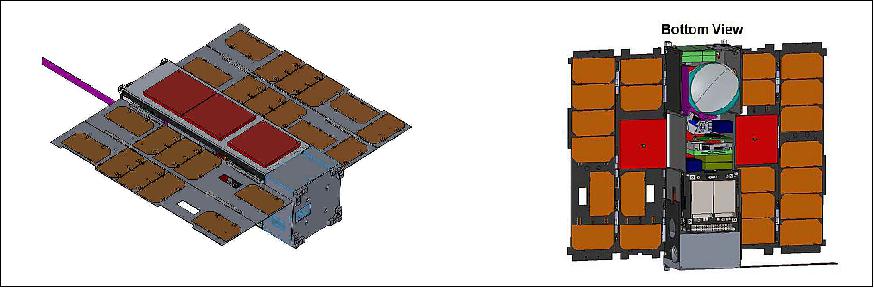
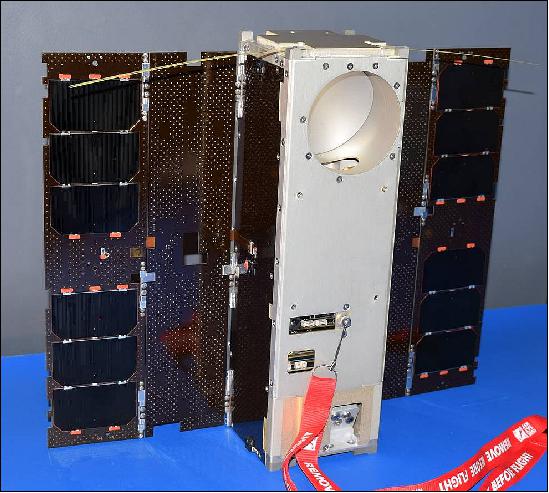
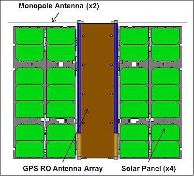
MiRaTA is a 3U CubeSat with a size of 10 cm x 10 cm x 34 cm and a mass of ~ 4.5 kg (max). The MiRaTA bus design is simpler in many respects than its predecessor, MicroMAS (Micro-sized Microwave Atmospheric Satellite), which had a scanning mechanism. There are no active mechanisms on MiRaTA, and the only deployable structures are two solar panels and a simple tape-spring antenna for UHF communications with the NASA Wallops Flight Facility ground station. The radiometer views the Earth through the nadir deck of the spacecraft, and in this frame, the GPSRO patch antennas have a field of view in the zenith direction.
ADCS (Attitude Determination and Control Subsystem): The pointing requirements are met with sensor and actuator systems that are similar to those used on MicroMAS, including the MAI-400 reaction wheel assembly, three earth horizon sensors (two integrated in the MAI-400 and one additional to support the pitch-up maneuver), tri-axial magnetometer, sun sensors, and magnetorquers for detumbling and reaction wheel desaturation. The current estimate of the ADCS mass is about 0.75 kg. with power consumption during nominal use of about 4 W.
EPS (Electrical Power Subsystem): To meet the MiRaTA mission goals, the average energy required per orbit is about 8.25 W hr, and the power and lifetime requirements are met with > 20% margin using a 20 W hr Clyde Space Li-ion battery, and double-deployed solar panels. The 20 W hr battery meets power and lifetime requirements if discharged less than 30% to maintain 80% of its initial capacity by the end of the 90 day validation period. The current estimate of the power system mass is about 1.0 kg and power consumption about 0.3 W.
C&DH: MiRaTA will use a Pumpkin CubeSat motherboard with a PIC24 microcontroller running the Salvo Real Time Operating System. This is the same general approach used on the previous MicroMAS CubeSat, Custom interface boards will supply power and data connections to the other subsystem components. The current estimate of mass is about 0.2 kg and power consumption is 0.4 W.
RF Communications: MiRaTA will use the same L3 Cadet nanosatellite UHF radio as MicroMAS, and plans to also use the Wallops 18.3 m dish for the ground station. Link budget analyses indicate >10 dB margin from the ISS orbit. The current estimate of the communications system mass is about 0.15 kg and average power of 0.5 W although the power increases to several watts during transmission intervals (communications passes are generally less than ten minutes long).
Development Status
• September 2017: The MiRaTA CubeSat has completed integration and environmental testing, and is awaiting launch as part of the ELaNa XIV in 2017 with the Joint Polar Satellite System 1 (JPSS-1). All tests have been completed, including both self-imposed tests as well as tests required by the launch service provider. A payload thermal vacuum test was conducted involving a spinning payload with a cold blackbody target and a hot blackbody target to confirm proper functioning of the MiRaTA radiometer. 8)
Launch
The MiRaTA 3U CubeSat was launched as a secondary payload on Nov. 18, 2017 on a Delta-2-7920 vehicle of ULA (United Launch Alliance) from VAFB, CA. The primary mission was the JPSS-1 spacecraft of NOAA, developed at NASA. 9) 10)
Orbit: The design orbit for the MiRaTA mission is an elliptical sun-synchronous orbit with a perigee of 450 km and an apogee at 810 km, inclination = 97.2º, LTAN (Local Time of Ascending Node) = 13:25 hours.
Orbit of JPSS-1: Sun-synchronous orbit, altitude of 824 km, inclination = 98.7º, period = 101 minutes.
Note: Initially, the MiRaTA nanosatellite was planned to be launched to the ISS in 2016 and to be deployed from there.
Secondary Payloads
• RadFxSat (Radiation Effects Satellite, Fox-1B), a 1U CubeSat of AMSAT and Vanderbilt University, Nashville, TN, USA.
• EagleSat, a 1U CubeSat of ERAU (Embry-Riddle Aeronautical University), Prescott, AZ, USA.
• MakerSat-0, a 1U CubeSat of NNU (Northwest Nazarene University) of Nampa, Idaho, USA.
• MiRaTA (Microwave Radiometer Technology Acceleration), a 3U CubeSat of MIT (Massachusetts Institute of Technology), Cambridge, MA, USA.
• Buccaneer RRM (Buccaneer Risk Mitigation Mission), a 3U CubeSat technology mission of UNSW (University of New South Wales), Canberra, Australia and DST (Defence Science and Technology) group. The goal is to calibrate JORN (Jindalee Over-the-Horizon Radar Network).
Sensor Complement
The MiRaTA nanosatellite will contain two complete instrument systems, a tri-band atmospheric sounder and a Compact TEC (Total Electron Count)/Atmosphere GPS Sensor (CTAGS). These two instruments will be operated in a manner to allow cross-comparison and cross-calibration.
Some background: Microwave radiometers are one of the workhorse instruments aboard today's weather satellites. These sensitive instruments measure radio frequency signals related to the thermal radiation emitted by atmospheric gases, such as molecular oxygen and water vapor, and also detect particles such as cloud ice. These data are key inputs for models that track storms and other weather events. Calibrating these radiometers is important for keeping them from drifting so their data can be used for accurate weather and climate models. Therefore, a calibration target is usually included in the satellite to help the radiometer maintain its accuracy. 11)
Miniaturizing microwave radiometer instruments to fit on a CubeSat leads to the challenge of finding a calibration instrument that is not only accurate but also compact, said Kerri Cahoy, principal investigator for MiRaTA and an associate professor in the Department of Aeronautics and Astronautics at the Massachusetts Institute of Technology. "You don't have room for the bulky calibration targets that you would normally use on larger satellites," Cahoy said. "Microwave radiometer calibration targets on larger satellites can be the size of a toaster, but for CubeSats, it would have to be the size of a deck of cards."
Cahoy and her colleague William Blackwell, the microwave radiometer instrument lead at MIT Lincoln Laboratory, have come up with a solution based on a technique she studied in graduate school called RO (Radio Occultation), whereby radio signals received from GPS satellites in a higher orbit are used to measure the temperature of the same volume of atmosphere that the radiometer is viewing. The GPS-RO temperature measurement can then be used for calibrating the radiometer.
"In physics class, you learn that a pencil submerged in water looks like it's broken in half because light bends differently in the water than in the air," Cahoy said. "Radio waves are like light in that they refract when they go through changing densities of air, and we can use the magnitude of the refraction to calculate the temperature of the surrounding atmosphere with near-perfect accuracy and use this to calibrate a radiometer."
In 2012, NASA's InVEST (In-Space Validation of Earth Science Technologies) program issued a request for technology demonstration proposals, which prompted Blackwell and Cahoy, who was then teaching at MIT, put their theory to the test by offering a project to Cahoy's students in her sensors and instrumentation class to determine if the idea was feasible. When two students demonstrated through computer modeling that radio occultation could indeed function for radiometer calibration, Cahoy and Blackwell asked The Aerospace Corporation's Rebecca Bishop, who has developed GPS-RO receivers for CubeSats, to join the team. They then submitted a full proposal for MiRaTA to NASA, which gave the greenlight for funding in the spring of 2013.
Building MiRaTA was a team effort. Bishop modified an off-the-shelf, low-cost GPS receiver to make the radio occultation measurements for calibration; MIT Lincoln Laboratory and University of Massachusetts Amherst applied their engineering skills to further miniaturize the microwave radiometer; and Cahoy and her student team, guided by expert mentors at MIT Lincoln, built the satellite that would house everything.
"Building a CubeSat can be hard because you have to put batteries, a radio, a computer, your instruments, wheels that you spin to tip and turn your satellite, and folded solar panels and antennas all into a very small space," Cahoy said. "And you're using the space equivalent of scotch tape and super glue to constrain this mess of wires and connectors and get it into its housing. "But," Cahoy added, "the hard work will really pay off in great science data if it all goes as planned."
In the best-case scenario, three weeks after launch MiRaTA will be fully operational, and within three months, the team will have obtained validation data from both the radiometer and the GPS receiver. The big goal for the mission—declaring the technology demonstration a success—would be confirmed a bit farther down the road, at least half a year away, following the data analysis.
If MiRaTA's technology validation is successful, Cahoy said she envisions an eventual constellation of these CubeSats orbiting the entire Earth, taking snapshots of the state of the atmosphere and weather every 15 minutes—frequent enough to track storms, from blizzards to hurricanes, in real time. "Our goal is to have our radiometers perform just as well as those on current weather satellites and be able to provide the kind of data that helps agencies and people in the path of a natural disaster prepare early and wisely," she said.
"This is a very exciting mission as it will be the first on-orbit demonstration of an all-weather, three-frequency radiometer CubeSat using atmospheric GPS-RO-based calibration," said NASA Jet Propulsion Laboratory's Charles Norton, a program associate in NASA's ESTO (Earth Science Technology Office) and the task manager for MiRaTA. "It's a true testament to the creativity and innovation of the teams involved that they're advancing measurement technologies for future small satellite constellation missions," he said, while adding that USU/SDL (Utah State University's Space Dynamics Laboratory) and NASA Wallops Flight Facility are supporting ground station and mission operations for the CubeSat.
Small satellites, including CubeSats, are playing an increasingly larger role in exploration, technology demonstration, scientific research and educational investigations at NASA, including: planetary space exploration; Earth observations; fundamental Earth and space science; and developing precursor science instruments like cutting-edge laser communications, satellite-to-satellite communications and autonomous movement capabilities.
MWR (Microwave Radiometer)
The tri-band microwave atmospheric sounder provides collocated observations over three frequency bands, 52-58, 175-191, and 206-208 GHz and comprises two radiometer subsystems (Figure 4). The specific frequency plan and radiometer design is ongoing, and slight modifications to the radiometer system are expected. The MWR development is a collaboration between the University of Massachusetts at Amherst and MIT/LL.
• Subsystem 1) is a V-band (52-58 GHz) receiver ("front end") with weakly coupled noise diode, low-noise MMIC amplifier, mixer, IF (Intermediate Frequency ) preamplifier, and ultracompact IF spectrometer ("back end") with a highly-scalable LTCC/SIW architecture operating over the 23-29 GHz IF band to provide six channels with temperature weighting functions approximately uniformly distributed over the troposphere and lower stratosphere.
• Subsystem 2) is a broadband G-band mixer front end operating from 175.31 to 208.4 GHz with a conventional IF spectrometer back end with lumped element filters. The V-band front end and the G-band back end are currently at very high TRL, having been flown on several spaceborne systems. MiRaTA will advance the TRL for the ultracompact IF spectrometer back end and the broadband G-band mixer front end from TRL5 to TRL7.
Channel ID | Type | Center Frequency (GHz) | Bandwidth (MHz) | Weoghting Function Peak Height (km) |
V1 | Single Side Band | 50.30 | 180 | 0 |
V2 | 51.76 | 400 | 0 | |
V3 | 52.80 | 400 | 2 | |
V4 | 53.50 | 600 | 5 | |
V5 | 54.40 | 400 | 8 | |
V6 | 54.94 | 400 | 11 | |
V7 | 55.50 | 330 | 13 | |
G1 | Double Side Band | 183.31±3 | 1000 | 4 |
G2 | 183.31±7 | 2000 | 2 | |
G3 | Will fly on EON-MW | 204.8 | 2000 | 1 |
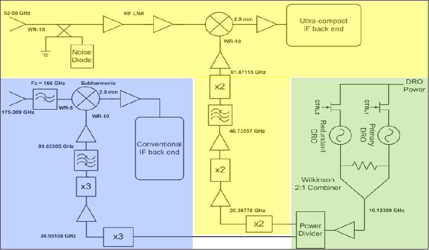
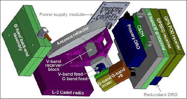
Legend to Figure 4: MiRaTA provides all-weather temperature, humidity, and cloud ice measurements for weather forecasting and climate studies. The V-band (yellow) and G-band (blue) receiver systems are completely independent, with a redundant dielectric resonator oscillator (green) common to both.
The ultra-compact back-end spectrometer used in the MiRaTA V-band radiometer is shown in Figure 5. The spectrometer has been fabricated using LTCC (Low-Temperature Co-fired Ceramic) technology, which supports multiple metal levels and embedded passive components. The dielectric constant is relatively high, thereby reducing the feature size. The filters have been implemented using the SIW (Substrate Integrated Waveguide) technique, allowing high-performance filters to be realized using standard circuit board fabrication techniques to reduce cost. The spectrometer has been extensively tested and yields excellent performance. The packaged, flight-ready subassembly consumes about 370 mW of power with a mass of about 90 g. The electronics feature a low-power mode that will be used in the "off" portion of the mission duty cycle to improve stability and radiometric performance. The six V-band channels span approximately 52.5 to 56.1 GHz in contiguous 600 MHz bands to provide nearly uniform vertical coverage from the surface to approximately 20 km at nadir viewing incidence, which satisfies the PATH (Precipitation and All-weather Temperature and Humidity) requirements. Note: The PATH mission, using a microwave array spectrometer, was recommended to NASA as one of the 15 decadal-survey missions of the NRC (National Research Council) in 2007.
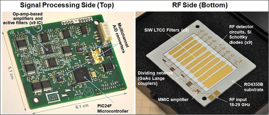
Legend to Figure 5: The top side of the board contains the analog and digital signal processing electronics and interfaces to the C&DH (Control and Data Handling) radiometer module. The bottom side of the board contains the microwave components needed for power division, amplification, filtering, and detection. A low-mass, RF-tight enclosure has been fabricated using metal-coated, metal-infused ULTEM®.
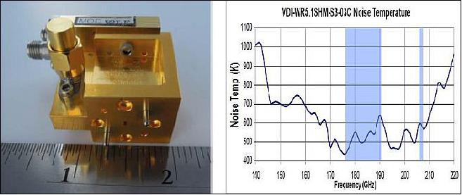
A recent innovation in millimeterwave receiver development is the construction of broadband mixers that provide useful performance over a wide intermediate frequency range. VDI (Virginia Diodes, Inc.) has recently demonstrated a sub-harmonic mixer at TRL5 (shown in Figure 6) operating near the 183.31 GHz water vapor line that also allows simultaneous observation of a cloud ice channel near 210 GHz without separate down-conversion. This simplifies the receiver hardware and enables very compact designs supporting multiple atmospheric bands. The required LO power (2-4 mW) is provided by a compact multiplier chain driven by a dielectric resonator oscillator.
This receiver architecture is quite suitable to CubeSat implementation due to the small size and potential for highly integrated packaging (the feed horn will attach directly to the mixer, for example) and has been demonstrated successfully for the MicroMAS CubeSat program at 118 GHz. The G-band radiometer will provide double-sideband measurements centered about the 183.31 GHz water vapor line: ±1 GHz (500 MHz bandwidth), ±3 GHz (1 GHz bandwidth), and ±7 GHz (2 GHz bandwidth). A fourth, single-sideband channel will be observed from 206.4-208.4 GHz. A high-TRL conventional IF back-end filterbank will be used with simple lumped-element and coupled stripline circuits. Power supplies for all needed bias lines will be built into the receiver blocks to minimize size. The radiometer CAD model for both the V- and G-band systems contains connectors and fasteners to ensure mechanical compatibility with the CubeSat structure. Thermal and structural analyses have also been performed to increase design fidelity, and heater provisions are included in the design, mass, and power budget. The MiRaTA radiometer system implementation is highly mature and based heavily on experience with similar flight systems, thereby reducing risk.
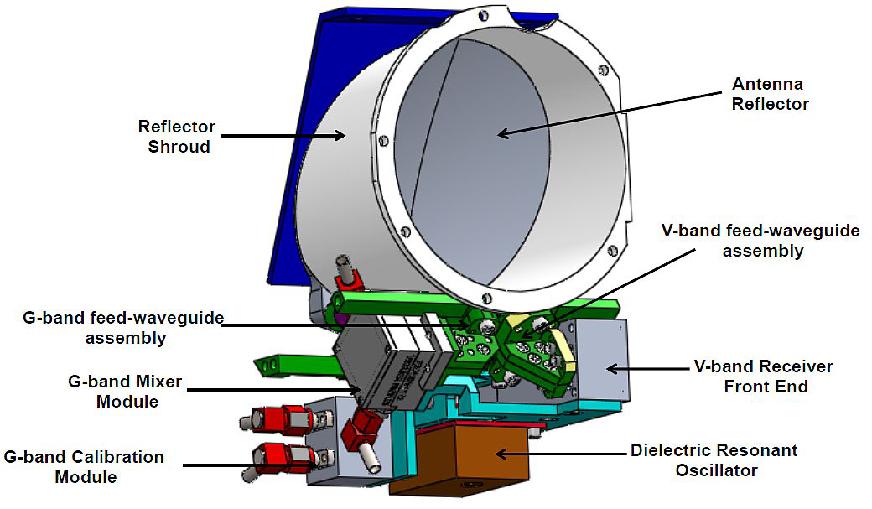
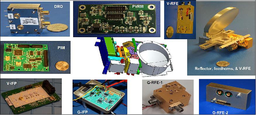
The V- and G-band radiometer systems are integrated in a payload assembly, shown in Figure 7. The V-band front end comprises a high-excess-noise-ratio weakly-coupled noise diode for calibration, followed by a low-noise RF MMIC preamplifier. Two scalar feed horns illuminate an offset parabolic reflector yielding FWHM beamwidths (aligned in the pitch plane) of approximately 1.25º and 5º for the G- and V-band systems, respectively, with >95 beam efficiency. These beamwidths meet PATH requirements from an ISS orbit, and the design can easily be scaled to use a larger aperture that could be accommodated on a 6U CubeSat operating at higher orbit altitudes. The DRO is fully redundant and shared among the two receivers.
CTAGS (Compact TEC (Total Electron Count)/Atmosphere GPS Sensor)
GPSRO (GPS Radio Occultation) measurements have been used extensively to improve weather forecasting and assessments of climate. Temperature profile accuracies approaching 0.1 K are achievable in the upper troposphere and lower stratosphere, and recent work has presented techniques for probing down to the boundary layer. GPS-RO measurements are well-calibrated due to their fundamental dependence on time delays, which can be traced to NIST (National Institute of Standards and Technology) standards.
However, GPSRO measurements have relatively sparse geospatial coverage. When the COSMIC/FORMOSAT-3 constellation was at peak operational capacity, it provided approximately 2,000 occultation profiles per day, compared with over 3,000,000 soundings per day for ATMS (Advanced Technology Microwave Sounder).The MiRaTA mission will demonstrate the combined use of passive microwave sounding and GPSRO observations to leverage the benefits of both in order to achieve highly accurate calibration with dense geospatial sampling.
Furthermore, the project investigates a new method of a two-point calibration, where the traditional calibration points of cold sky and warm ICT (Internal Calibration Target) are replaced with a cold sky and a warm noise diode turned on and off against the cold sky. The noise from the diode is sufficiently strong that a weak coupler can be used and avoids the need for a switch as the noise diode is always in the signal path, but only produces noise when energized with an appropriate bias current (usually on the order of 5-10 mA). The noise diode is periodically calibrated with GPSRO measurements to mitigate any drift . In addition to offering improved calibration, this method also dispenses with the need for an ICT, which can be bulky, susceptible to errors, and often drives the design of the radiometer antenna and scanning system. The GPSRO instrumentation is very compact and places no restrictions on the design of the radiometer. CubeSat class spacecraft (3U) can now accommodate both radiometers and GPSRO systems on the same spacecraft, offering a low-cost, high-performance sounding platform.
GPSRO with the Compact TEC/Atmosphere GPS Sensor
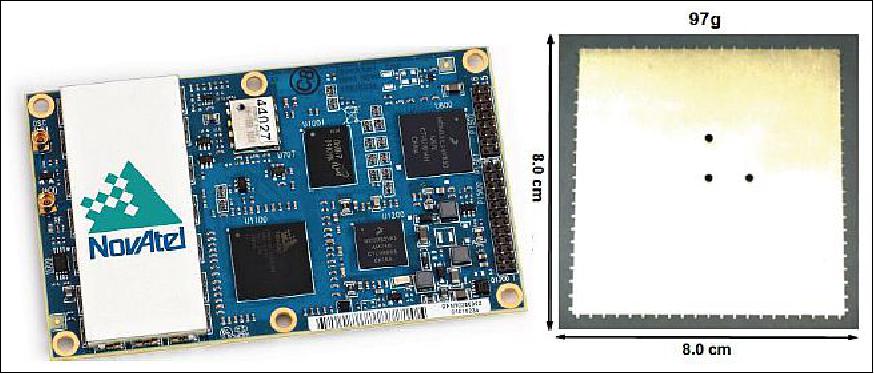
GPSRO sensors provide all-weather atmospheric temperature measurements with high accuracy and precision. To date, size, power, and antenna gain requirements for GPSRO atmospheric sensors (as opposed to ionospheric sensing, where GPSRO has been demonstrated on nanosatellite platforms) have precluded their use on CubeSats. A new GPS receiver, the NovAtel OEM628 currently at TRL5, together with a multi-element antenna array (3 or 5 patch antennas), enables atmospheric GPSRO from CubeSats.
With MiRaTA, a 3U CubeSat-compatible atmospheric GPSRO sensor will be validated at TRL7. The CTAGS (Compact TEC /Atmosphere GPS Sensor) to be flown on MiRaTA is a GPSRO sensor based on the successful CTECS (Compact Total Electron Content Sensor) that will obtain atmospheric temperature profiles down to at least 20 km altitude in addition to ionospheric measurements. CTAGS extends the capability of CTECS by using a more compact and capable GPS receiver and a relatively high-gain patch antenna array that will allow measurements into the lower atmosphere. The CTAGS sensor consists of four components (Figure 9): 1) multi-element antenna array, 2) single patch antenna for precision orbit determination, 3) LNA (Low-Noise-Amplifier), and 4) NovaTel GPS receiver.
Modifications are needed in order to adapt a GPSRO sensor for tropospheric sounding onto a CubeSat. First, a higher gain antenna is required to retain lock on the GPS signals as the satellite sets behind the Earth from the perspective of MiRaTA and the signals pass through the denser lower atmosphere. The gain improvement is achieved by an array of patch antennas. Each individual patch antenna will use the heritage CTECS antenna design. The antenna array improves the gain to over 10 dBi and also creates a directional pattern. The antenna boresight will be directed toward the limb by maneuvering the spacecraft ( Figure 3). Figure 1 illustrates the CTAGS antenna array on the MiRaTA spacecraft as embedded in the deployed solar panels. CTAGS utilizes the NovAtel OEM628 receiver. This receiver is smaller in size and power than the CTECS receiver and has improved capabilities. The OEM628 receiver has not flown in space before, but is now commercially available at TRL5. The receiver can track up to 120 signals (60 dual frequency satellites) at any time, thereby permitting both atmospheric and navigation observations.
Calibration of the Microwave Radiometer with GPSRO
Absolute calibration of spaceborne microwave scanning instruments for high-fidelity atmospheric research is immensely challenging and difficult to fully trace to a reference standard , although recent work has shown promise to establish brightness temperature standards with uncertainties of approximately 0.7 K. As a direct result of these calibration challenges, bias corrections of up to several Kelvins are routinely used. Problems associated with reflector emissivity and ICT contamination have been reported. Previous comparisons of AMSU-A observations that were collocated to COSMIC/FORMOSAT-3 GPSRO observations indicated biases as large as 1.92 K.
The CCA recommends improved radiometer calibration, which is profoundly challenging even in flagship-class systems such as ATMS (Advanced Technology Microwave Sounder) on the Suomi NPP mission and the GMI (Microwave Imager) on GPM ( Global Precipitation Mission), and even more so for a CubeSat radiometer. Several approaches have been proposed that fall far short of climate-quality calibration. Noise diodes can be used to inject a calibration signal into the radiometer with relatively low loss, however, the signal drifts appreciably. Internal matched loads can be switched into the radiometer signal path, but the switches add loss (>2dB at 183 GHz), precluding their use in systems that require coverage of large areas on short time scales, such as PATH. Perhaps most importantly, neither approach permits complete "through-the-antenna" calibration. The GPSRO and MWR approach directly addresses these challenges to offer climate-quality, through-the-antenna calibration of CubeSat radiometers. The concept is to use noise-diodes on short time scales and collocated GPSRO measurements on longer time scales to calibrate the noise diode to very high accuracy and stability. This technique could be implemented operationally using radiometer cross-track scanning and sideward-looking GPSRO observations (available every ~15 minutes) to permit simultaneous limb sampling. Calibration to "GPSRO measurements of opportunity" are insufficiently coincident in space and time to allow high-fidelity radiometer calibration.
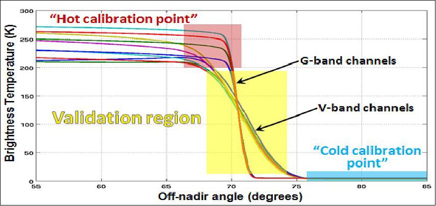
An innovation within the MiRaTA technology validation program is the use of the Earth's limb as a brightness temperature reference. There are several key benefits to this approach:
1) Nearly the entire dynamic range of the radiometers is covered with each scan of the limb as shown in Figure 10, permitting extensive calibration (note hot and cold calibration sources in Figure 10) and validation with relatively few scans (readily collected over a 60 day validation period).
2) The largest sources of validation error in the non-opaque radiometer channels are surface emissivity and boundary layer temperature variability, and these are minimized to negligible levels because of increased absorption due to the longer line-of-sight associated with the limb viewing geometry.
3) The regions of maximum sensitivity (vs. altitude) of the radiometer and GPSRO observations are very closely aligned in the upper troposphere and lower stratosphere.
4) The path through the atmosphere of the radiometer and GPSRO line-of-sight is almost identical, minimizing co-location error.
5) The shape of the limb brightness temperature distribution with angle can be used to estimate radiometer boresight direction with very high accuracy.
Science Concept of Operations
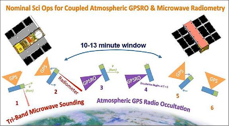
In order to achieve its mission goal of radiometer calibration through GPSRO measurements, MiRaTA performs a slow pitch-up to allow its radiometer and GPS receiver payloads to sound overlapping volumes of Earth atmosphere where sensitivity, calibration, and dynamic range are optimal. 12) 13)
The spacecraft will periodically slew from a radiometer nadir pointing attitude, LVLH (Local Vertical Local Horizontal, to a 90-105° pitch angle and back. A diagram of this maneuver is shown in Figure 1. The MiRaTA's 3-axis stabilized ADCS controls this pitch maneuver. During steps 1 and 2 in Figure 11, the radiometer passes over, or sounds, a volume of Earth's atmosphere. In steps 3 and 4, the onboard GPS receiver - CTAGS (Compact TEC (Total Electron Content)/Atmosphere GPS Sensor) antenna beam points toward the Earth's limb and receives signals from one or more satellites in the GPS constellation as they appear to "set" behind (are "occulted by") the Earth from MiRaTA's perspective (Figure 11, steps 3 and 4). The volumes of atmosphere sounded in steps 1 to 2 and 3 to 4 should overlap as much as possible to achieve a good calibration. The sequence of radiometer sounding, then pitch-up, GPSRO collection, and subsequent pitch-down maneuver is expected to last approximately 22 – 32 minutes.
Automating Science Planning
One of MiRaTA's mission goals is to successfully perform at least 100 of these science calibration maneuvers over the course of a 60-day primary mission operations period. The timing for the maneuvers depends on orbital geometry, particularly achieving the desired alignment between the radiometer field of view and the location of the GPSRO measurements. Given the relatively infrequent opportunities for ground contacts (a representative day contains two sets of three short ground passes separated by about 90 minutes, with the two sets separated by about 10 hours), the spacecraft must be capable of performing these maneuvers without human-in-the-loop supervision during the actual maneuver.
The project plans to perform the maneuvers in a scripted fashion, with operations scripts derived in advance on the ground from predicted orbital parameters and uplinked to MiRaTA during ground contacts with the mission's ground station at NASA Wallops. In order to ensure the successful execution of multiple maneuvers over long periods without ground contact, these scripts must also manage onboard resources effectively, including energy stored in the spacecraft batteries and storage of the science and engineering telemetry data collected. The same needs are common to many types of Earth observation missions. For this reason,the project decided to design an algorithm, the RASP ( Resource-Aware SmallSat Planner) that could build these scripts in an automated way by reasoning about the timing of maneuver opportunities and other onboard activities as well as the spacecraft resource states at any given time.
Modeling MiRaTA Operations
The project developed a simple but representative model of MiRaTA's operations that can be used for automated planning.
Calculation of Maneuver Times: There are specific times when the maneuver activity can be performed, given MiRaTA's orbit and positioning relative to GPS satellites. To simulate the GPSRO accesses that would overlap with the radiometer field of view, a scenario was set up using AGI (Analytical Graphics, Inc's) Systems Toolkit (STK). The satellite was placed in the reference orbit , and line-of-site accesses to each satellite in the GPS constellation were computed. From each access, we were interested in the range, azimuth, and elevation of each GPS satellite relative to MiRaTA.
The science maneuver was modeled assuming the spacecraft was at a 100º pitch-up angle (relative to LVLH) across the entire orbit (rather than changing the pitch-up angle based on altitude for each maneuver). The radiometer sensor field of view is assumed to be a 2º full angle, offset from the spacecraft orbital plane by +5º. The project identified the set of GPS occultations that overlapped with this radiometer field of view (174º-176º azimuth, -20º to 0º elevation) and that passed through the area of highest gain on the patch antenna feeding MiRaTA's GPS receiver to determine the frequency and duration of viable GPS occultation opportunities. A representative set of GPSRO accesses from a 24-hour period is shown in Figure 12.
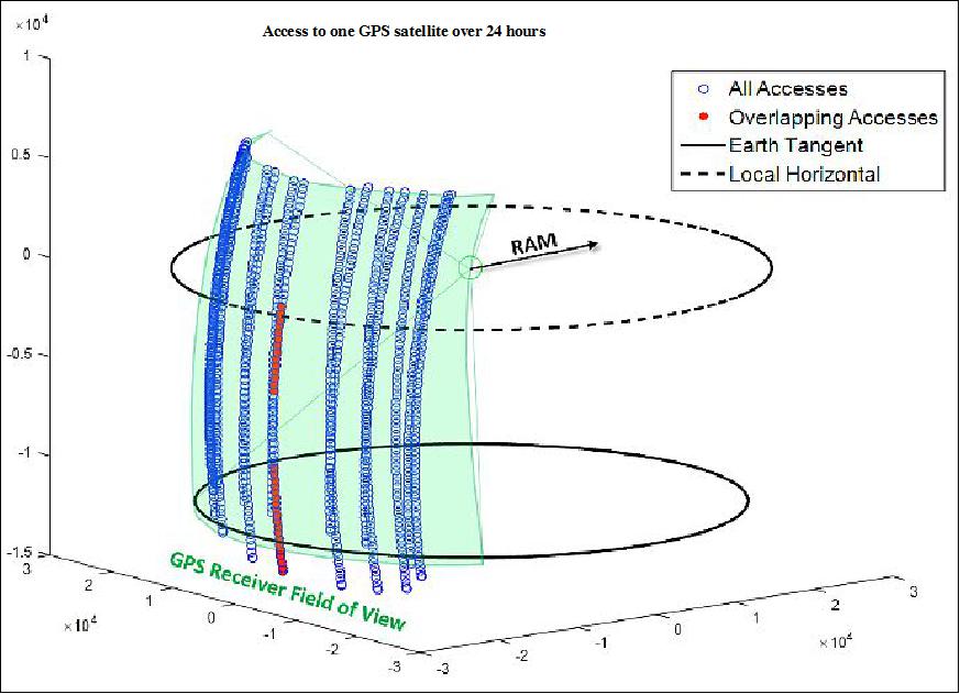
Preliminary results indicate that over a 24-hour period an average of 2-3 setting occultations will occur that overlap with the radiometer field of view, and the overlap will last for 5-7 minutes. For the purposes of demonstrating automated science planning in this work, we relaxed the radiometer field of view elevation restriction and considered all GPS satellites that passed through the radiometer's azimuth range. This relaxation results in more maneuver access times being considered by the algorithm and a more thorough assessment of the algorithm's planning robustness.
Onboard Energy Production and Storage: MiRaTA has two sets of double-deployed solar panels that can generate up to 24.8 W in total when fully illuminated at normal incidence as shown in Figure 13.
When the spacecraft is in LVLH orientation, the spacecraft is in an overall energy negative situation. To stay power positive, the ADCS system will implement a sun-tracking attitude in which the zenith face of the spacecraft is pointed within 20º of the sun vector. There are, however, several circumstances that can prevent the spacecraft from maintaining a default sun-tracking attitude:
• All science maneuvers must start from an LVLH orientation
• The spacecraft must be in LVLH when communicating with the ground station
• The LVLH attitude is the lowest-drag configuration, which is especially necessary for low-altitude orbits (e.g. ISS deployment).
The day-to-day (and orbit-to-orbit) operations of the satellite must take into account these constraints as well as a requirement to keep the battery (20 W hr lithium polymer) above a 30% depth of discharge at all times.
Onboard Data Production, Storage, and Downlink: MiRaTA produces a large amount of science data during its science maneuver, greater than 60 Mbit for a maneuver with 15 minutes of high rate GPS signal tracking. It also continually produces both spacecraft bus and payload housekeeping data. To meet the requirement to get all this data to ground, the spacecraft has a radio for high data rate downlink. The radio nominally operates at an effective 2.6 Mbit/s data rate over a link with the mission's dedicated ground station at NASA Wallops at latitude and longitude 37.86º and -75.51º, respectively.
Spacecraft Attitude Control Model: The MiRaTA design includes a dedicated ADCS package with a sensor and actuator suite, capable of achieving sub-degree level pointing accuracy. Attitude determination is achieved with three Earth horizon sensors, six coarse sun sensors, and a 3-axis magnetometer. Actuation is achieved with three reaction wheels and magnetorquers. The system is sized to achieve MiRaTA's science maneuver and maintain pointing in LVLH and sun tracking modes during nominal operations without saturating the reaction wheels. Continual desaturation via the magnetorquers aids this process.
Operational State Machine and Activities: Figure 14 presents a state machine representation of the operational activities (modes) for MiRaTA. During operations the spacecraft is assumed to be in one and only one of these modes at any given time. Each mode corresponds to an activity that the spacecraft is performing, and the spacecraft can transition between activities along any of the arrows in the state machine. The science maneuver is represented by "Maneuver", at the top. The Recharge activity corresponds to the dedicated ADCS mode when the spacecraft tracks the sun. The Downlink activity corresponds to a downlink to the ground station. The Slew activity is when the spacecraft uses the ADCS actuator suite to change its attitude. A conservative assumption is made that a slew must occur between any maneuver and resource management activity, including two of the same activity in a row. The Idle activity occurs when no other activities are ongoing.
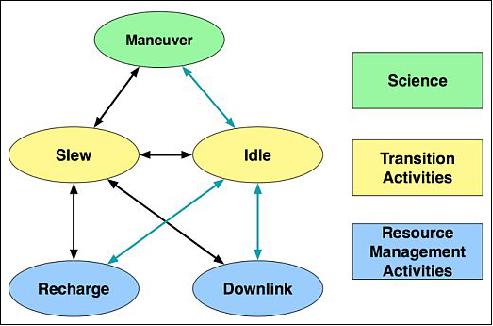
Resource usage is broken down by activity in Table 2. The energy usage values in the table were calculated including all power draws from activated components by mode. We assume here that energy is only produced recharge mode, when the spacecraft maintains an attitude that maximizes solar power produced (~24.8 W). The MiRaTA spacecraft will in actuality have solar power input during other modes, depending on orbital geometry. The restriction to recharge mode here simplifies the model while maintaining a conservative estimate of power production.
The data production values in the table include the production of spacecraft bus housekeeping and payload housekeeping telemetry. For the maneuver mode, the nominal GPSRO data production rate (63.2 kbit/s, tracking three GPS satellites at 50 Hz sampling rate) is added in, and assumed to occur over the entire duration of the maneuver. Downlink uses the nominal radio downlink data rate, 2.6 Mbit/s.
Parameter | Operational State | ||||
Maneuver | Recharge | Downlink | Slew | Idle | |
Energy Storage (ES), W | -15.1 | 16.1 | -16.4 | -7.8 | -7.3 |
Data Storage (DS), kbit/s | 73 | 10 | -2600 | 10 | 10 |
Minimum duration, minutes | 10 | 1 | 0 | 3 | 0 |
RASP (Resource-Aware Smallest Planner) Algorithm
The RASP algorithm was developed to autonomously plan and schedule activities onboard a resource-constrained small satellite. The discussion of the algorithm follows its previous introduction by Kennedy and Cahoy 14), with more detail added. The algorithm has some similarities with the ASPEN/CASPER algorithms developed at NASA JPL 15) in that it evaluates the feasibility of performing activities based on onboard resource usage, but it a) uses a simpler model focused specifically on a resource-constrained satellite and b) it constructs an entire activity sequence in a single algorithm, as opposed to creating an initial high level sequence for later onboard refinement.
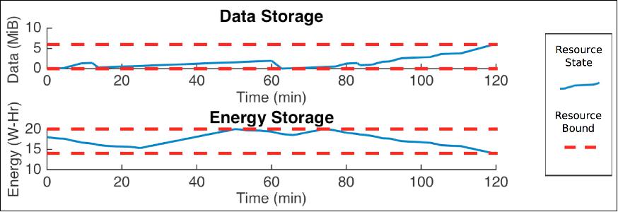
Activity planning constitutes the selection of a set of activities (an "activity sequence") from the operational state machine (Figure 14) that allows the satellite to execute as many science maneuver activities as possible while maintaining onboard resources within constraint limits. Scheduling is the assignment of a set of start and end times to every activity in the plan (an "activity timeline") such that an overall score function is maximized as well as the determination of acceptable trajectories for onboard resource states. Figure 15 illustrates two example resource trajectories that are kept within resource bounds.
The interested reader is referred to Ref. 12) for detailed information on the RASP algorithm.
In summary, the RASP algorithm was demonstrated over a representative 24 hour simulation of MiRaTA's orbit over which 19 science maneuver windows were found. The algorithm produces, from a set of simple time window inputs, consistent activity plans that allow the spacecraft to schedule radiometer-GPSRO calibration maneuvers while keeping within constraints on onboard energy storage and data storage. No human-in-the-loop involvement is needed except for the initial production of time windows inputs.
The project showed, that RASP successfully balances the performance of maneuvers with onboard resource usage. We found that maneuver execution performance degrades slightly as the length of the RASP planning window increases; for a 60 minute planning window 16 out of 19 maneuver windows were executed and the total maneuver execution time was 176.7 minutes, and for a 240 minute planning window these decreased to 12 out of 19 and 143.36 minutes, respectively. The average maneuver window occupation (percentage of maneuver window executed over those maneuver windows which were executed) showed no consistent dependence on planning window length. It was shown, that while shorter planning windows did lead to more maneuvers being executed, this happened at the cost of small resource usage limit violations. In the 60 minute planning window case, the average ES (Energy Storage) margin was 62.9%. This margin increased to 71.1% for a 120 minute planning window, representing the fact that the 120 minute case does better at keeping ES away from its lower bound. These results show, that RASP plans well over a range of planning window lengths, and that if the mission is willing to take on more risk by allowing resources to occasionally exceed their pre-set limits, more science maneuvers can be achieved.
Limitations of Current Algorithm Implementation: One important limitation of the current implementation of RASP is that it is only capable of scheduling a single onboard activity at a time. The assumption for the MiRaTA CubeSat operations model used here is that science maneuvers can only physically occur one-at-a time. Significant development would be needed to generalize the algorithm to a simultaneous, multiactivity model while maintaining computational tractability.
The algorithm does not reason about the latency of the science data it has collected and is storing onboard; data is treated as a simple bulk item that is of equal value no matter how or when it is produced. This approach is of limited value operationally because in reality we do want to be able to treat time-sensitive science data and engineering telemetry differently.
Also, the algorithm does not model energy consumption and production separately, constraining it to a simple model of constant energy usage rate by spacecraft activity mode. We used a conservative assumption here, that energy can only be produced in recharge mode. In reality, the project could take advantage of solar power input during other modes as well.
Old Science Concept Operations Version for ISS Deployment of MiRaTA
The MiRaTA project baselines a launch from the ISS into a nominal orbit of ~400 km and 51.6° inclination. With a maximum mass of 4.5 kg, the mission lifetime should exceed 90 days. A simulation was also performed to assess mission lifetime from a ~400 km initial orbit (ISS) and considered worst-case drag configurations presented by the solar arrays during the pitch maneuver. Orbit decay to 300 km (minimum useable altitude) occurs in >90 days. The 90 days includes a 30 day EOC (Early Orbit Checkout) phase and a 60 day validation phase. EOC activities commence after launch and deployment and include solar panel deployment, ground communication, detumbling (estimated to be < 2 days), checkout of the attitude determination and control system (ADCS), slew to nominal flight orientation, monitoring of telemetry, and checkout of the GPS PNT (Position, Navigation, Time), the GPSRO, V-band radiometer, and the G-band radiometer instruments. The validation phase will then commence with the major objective being to obtain ~100 validation-quality Earth limb scans of radiometer and GPSRO data. Once this goal is achieved (which optimistically could be in as few as seven days, but conservatively there is significant schedule margin in the validation phase), additional opportunities for radiometric imagery will be sought (hurricanes, for example), and roll mode (scanning) will be initiated.
The MiRaTA MOT (Mission Operations Team) will have a MOC (Mission Operations Center) at MIT/LL that will connect to the NASA Wallops Flight Facility, and USU/SDL (Utah State University/Space Dynamics Laboratory) , Logan, UT, will use a software-defined radio ground station with the 18.3 m UHF antenna dish at Wallops. This arrangement was used successfully with the DICE (Dynamic Ionosphere CubeSat Experiment) mission and is also planned for the MicroMAS (Microsized Microwave Atmospheric Satellite) mission.
The primary MiRaTA mission ConOps is summarized in Figure 16. The MiRaTA spacecraft will perform a slow pitch up/down maneuver once per orbit to permit the radiometer and GPSRO observations to sound overlapping volumes of atmosphere through the Earth's limb, where sensitivity, calibration, and dynamic range are optimal. These observations will be compared to radiosondes , global high-resolution analysis fields, other satellite observations [ATMS/CrIS (Cross-track Infrared Sounder) on NPP/Suomi, etc.] and with each other (GPSRO and radiometer) using transfer models.
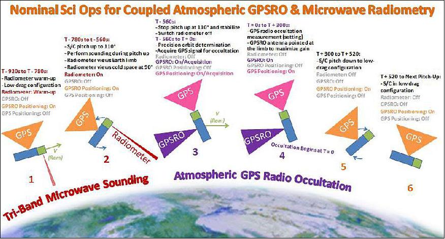
In addition to the advantages mentioned previously, this ConOps permits the radiometer and GPSRO systems to be powered on at different times in the maneuver, thus minimizing the potential for interference. The communication transmissions will be performed when the radiometer and GPSRO systems are powered down. A comprehensive orbital simulation was performed to assess the availability of high-quality setting occultations, and the project expects a minimum of five such opportunities per orbit.
Summary of MiRaTA Mission Goals
• At least 100 radiometer limb scans
• NEdT of 0.1 K at 55 GHz, 0.3/0.2/0.15 K at 183 ± 1/3/7 GHz, and 0.25 K at 207 GHz
• Radiometric accuracy of 1.5 K (V-band) and 2.0 K (G-band)
• GPSRO temperature retrieval rms error meeting JPSS requirements (approximately 1.5 K rms) down to 20 km, threshold, and 10 km, goal) (JPSS, 2011).
Item | Rationale |
Degree goal | Required to ensure collocation of radiometer and GPSRO measurements to within approximately 100 km |
Degree goal | Required to permit geolocation of the observations to within approximately 10% of the footprint size |
Minimum pitch rate of 0.5º/s | Ensure radiometric stability over the ~30 seconds of the limb scan for the G-band system (the V-band system will use a noise diode for calibration stability) |
Minimum average data rate of approximately 5 kbit/s | Required to transmit all observational and engineering data/metadata |
Power systems shall provide: 5.5 W to MWR (10 min per orbit, 0.5 W standby), 3.2 W to GPSRO (20 min per orbit, 0.5 W standby), 4.15 W to spacecraft (always), and 10 W for communication transmit (<1 min per orbit) | Power for technology validation demonstration and survival |
Minimum 90 day mission lifetime from 300-400 km orbit at 51.6º inclination | Time needed to fulfill objectives with >100% margin |
References
1) "In-Space Validation of Earth Science Technologies (InVEST)," NASA, 2012, URL: http://esto.nasa.gov/files/solicitations/INVEST_12/ROSES2012_InVEST_awards.html#black
2) William J. Blackwell, "New Techniques for High-Resolution Atmospheric Sounding," Lincoln Laboratory, MIT, Dec. 12, 2012, URL: http://weather.msfc.nasa.gov/sport/library
/sport_science_seminars/20121212_Blackwell/Blackwell_UAH_12Dec2012_small.pdf
3) William J. Blackwell, G. Allan, G. Allen, D. Burianek, F. Busse, D. Elliott, C. Galbraith, R. Leslie, I. Osaretin, M. Shields, E. Thompson, D. Toher, Kerri Cahoy, Pratik Dave, Andrew Kennedy, Ryan Kingsbury, Anne Marinan, Eric Peters, Christopher Pong, Meghan Quadrino, James (Mic) Byrne, Rebecca Bishop, James Bardeen, Neal Erickson, Chad Fish, Erik Stromberg, "Microwave Radiometer Technology Acceleration Mission (MiRaTA): Advancing Weather Remote Sensing with Nanosatellites," Proceedings of the 28th Annual AIAA/USU Conference on Small Satellites, Logan, Utah, USA, August 2-7, 2014, paper: SSC14-P4-12, URL: http://digitalcommons.usu.edu/cgi/viewcontent.cgi?
article=3015&context=smallsat
4) Kerri Cahoy, J.M. Byrne, T. Cordeiro, P. Davé, Z. Decker, A. Kennedy, R. Kingsbury, A. Marinan, W. Marlow, T. Nguyen, S. Shea, William J. Blackwell, G. Allen, F. Busse, C. Galbraith, A. Jensen, V. Leslie, I. Osaretin, M. DiLiberto, P. Klein, M. Shields, E. Thompson, D. Toher, D. Townzen, A. Vogel, Neal Erickson, "The Microwave Accelerometer Technology Acceleration CubeSat (MiRaTA)," ESTF 2014 (Earth Science Technology Forum), Leesburg, VA, USA, Oct. 28-30, 2014, URL: http://esto.nasa.gov/forum/estf2014/presentations/B2P3_Cahoy.pdf
5) W. Blackwell, J. Pereira, "New Small Satellite Capabilities for Microwave Atmospheric Remote Sensing: The Earth Observing Nanosatellite-Microwave (EON-MW)," Proceedings of the 29th Annual AIAA/USU Conference on Small Satellites, Logan, Utah, USA, August 8-13, 2015, URL:
http://digitalcommons.usu.edu/cgi/viewcontent.cgi?article=3292&context=smallsat
6) Bill Blackwell, "Preparations for the NOAA Earth Observing Nanosatellite-Microwave (EON-MW) Mission," Proceedings of the 31st Annual AIAA/USU Conference on Small Satellites, Logan UT, USA, Aug. 5-10, 2017, Pre-Conference Workshop Session 9: Instruments/Science 2, URL of abstract: http://digitalcommons.usu.edu/smallsat/2017/all2017/40/
7) W. Blackwell, D. Cousins, L. Fuhrman, "New Small Satellite Capabilities for Microwave Atmospheric Remote Sensing: The Earth Observing Nanosatellite-Microwave (EON-MW)," Proceedings of the 31st Annual AIAA/USU Conference on Small Satellites, Logan UT, USA, Aug. 5-10, 2017, Pre-Conference Workshop Session 9: Instruments/Science 2, URL of presentation: https://digitalcommons.usu.edu/cgi
/viewcontent.cgi?filename=0&article=3571&context=smallsat&type=additional
8) Kerri Cahoy, Gregory Allan, Zachary Lee, Ayesha Hein, Andrew Kennedy, Myron Lee, Erin Main, Bill Blackwell, "Integration and Test of the Microwave Radiometer Technology Acceleration (MiRaTA) CubeSat," Proceedings of the 68th IAC (International Astronautical Congress), Adelaide, Australia, 25-29 Sept. 2017, Pre-Conference Workshop, Session 8: Instruments/Science 1, URL of abstract: http://digitalcommons.usu.edu/smallsat/2017/all2017/32/ and URL of presentation: https://digitalcommons.usu.edu/cgi/viewcontent.cgi?filename=1&article=3563&context=smallsat&type=additional
9) Steve Cole, John Leslie, "NASA Launches NOAA Weather Satellite Aboard United Launch Alliance Rocket to Improve Forecasts," NASA, 18 Nov. 2017, Release 17-086, URL:
https://www.nasa.gov/press-release
/nasa-launches-noaa-weather-satellite-aboard-united-launch-alliance-rocket-to-improve
10) "ELaNa XIV CubeSats Launch on JPSS-1 Mission," NASA, 18 Nov. 2017, URL:
https://www.nasa.gov/feature/elana-xiv-cubesat-launch-on-jpss-1-mission
11) Samson Reiny, Sara Blumberg, "NASA CubeSat to Test Miniaturized Weather Satellite Technology," NASA CubeSats, Nov. 11, 2017, URL:
https://www.nasa.gov/feature/goddard/2017/cubesat-to-test-miniaturized-weather-satellite
12) Andrew Kennedy, Anne Marinan, Kerri Cahoy, James Byrne, Timothy Cordeiro, Zachary Decker, Weston Marlow, Stephen Shea, William J. Blackwell, Michael DiLiberto, R. Vincent Leslie, Idahosa Osaretin, Erik Thompson, Rebecca Bishop, "Automated Resource-Constrained Science Planning for the MiRaTA Mission," Proceedings of the 29th Annual AIAA/USU Conference on Small Satellites, Logan, Utah, USA, August 8-13, 2015, paper: SSC15-VI-1, URL:
http://digitalcommons.usu.edu/cgi/viewcontent.cgi?article=3201&context=smallsat
13) Kerri Cahoy, Anne Marinan,Timothy Cordeiro, William Blackwell, Rebecca Bishop, Neal Erickson, "Development of the Microwave Radiometer Technology Acceleration (MiRaTA) CubeSat for all-weather atmospheric sounding," Proceedings of the IGARSS (International Geoscience and Remote Sensing Symposium) 2015, Milan, Italy, July 26-31, 2015
14) Andrew K. Kennedy, Kerri L. Cahoy, "Onboard Operations Scheduling For A Cooperative Earth Remote Sensing Small Satellite Constellation," Proceedings of the 8th International Workshop on Spacecraft Constellations and Formation Flying, Delft, The Netherlands, June 8-15, 2015
15) S. Chien , G. Rabideau , R. Knight , R. Sherwood , B. Engelhardt , D. Mutz , T. Estlin , B. Smith , F. Fisher , T. Barrett , G. Stebbins , D. Tran, "ASPEN - Automated Planning and Scheduling for Space Mission Operations (2000)," International Conference on Space Operations (SpaceOps 2000), Toulouse, France: June 26-30, 2000, pp. 1–10
The information compiled and edited in this article was provided by Herbert J. Kramer from his documentation of: "Observation of the Earth and Its Environment: Survey of Missions and Sensors" (Springer Verlag) as well as many other sources after the publication of the 4th edition in 2002. - Comments and corrections to this article are always welcome for further updates (eoportal@symbios.space).
Spacecraft Launch Sensor Complement Concept of Operations References Back to top