MIOSat (Missione Ottica Su MicroSatellite)
EO
Atmosphere
Cloud type, amount and cloud top temperature
Aerosols
Quick facts
Overview
| Mission type | EO |
| Agency | ASI |
| Mission status | - |
| Launch date | 01 Jun 2014 |
| End of life date | 01 Jun 2016 |
| Measurement domain | Atmosphere, Land |
| Measurement category | Cloud type, amount and cloud top temperature, Aerosols, Multi-purpose imagery (land), Vegetation, Albedo and reflectance, Trace gases (excluding ozone) |
| Measurement detailed | Cloud cover, Land surface imagery, Vegetation type, Earth surface albedo, Land cover, NO2 Mole Fraction, Volcanic ash, CO2 Mole Fraction, CO Mole Fraction |
| Instruments | ALISEO, PAN CAM, Mach-Zehnder Micro-interferometer |
| Instrument type | Imaging multi-spectral radiometers (vis/IR), High resolution optical imagers, Atmospheric chemistry |
| CEOS EO Handbook | See MIOSat (Missione Ottica Su MicroSatellite) summary |
MIOSat (Missione Ottica Su MicroSatellite)
MIOSat (Optical Mission based on a Microsatellite) is an approved low-cost technology demonstration and Earth observation microsatellite mission of ASI (Italian Space Agency). In Dec. 2007, a contract was signed with an industrial group made up of Rheinmetall Italia (RhI), S.p.A. of Rome and Carlo Gavazzi Space S.p.A (CGS) of Milan to develop the spacecraft. Several other Italian companies, SMEs (Small and Medium-sized Enterprises) and Universities are involved in the development team with crucial roles. In this cooperative setup funded by ASI, RhI is the MIOSat mission manager (prime contractor) while CGS is the spacecraft manufacturer. 1) 2) 3) 4) 5)
MIOSat is a LEO microsatellite of ~ 120 kg with the objective to fly three innovative optical payloads: a) Sagnac interferometer, b) Mach Zehnder interferometer, and c) a high resolution panchromatic camera with a deployable telescope. In addition three technological experiment will be tested on-orbit.
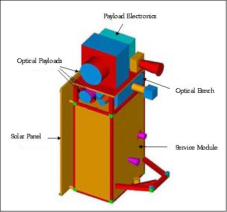
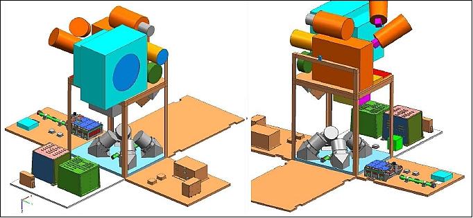
Spacecraft
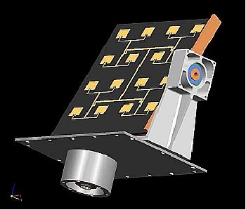
The spacecraft bus represents the first microsatellite platform designed and developed in Italy (CGS is the prime contractor of the spacecraft, bus development and spacecraft integration). The bus is modular and an agile platform (steering with a propulsion subsystem) capable to support future new technology experimentation and operative systems based on satellite formations. The bus structure uses an aluminum frame and side panels (honeycomb design) which are capable to provide the necessary strength and stiffness required by the launch vehicle. The thermal control is mainly passive and maintains the internal equipment within allowable temperature ranges during all mission phases. 6)
The spacecraft is designed for an operational lifetime of 3 years; it features an operative autonomy of up to 72 hours.
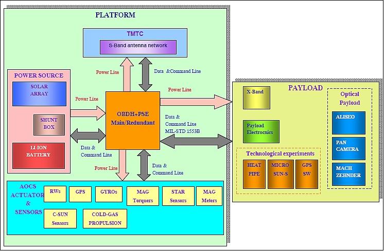
A CCM (Control & Configuration Module) receives information from the OBDH (On-Board Data Handling) system to configure the payload complement and transmit the compressed source data to the RF communication system. The OBDH elements consists of:
• OBC (Onboard Computer)
• Data acquisition module to interface with the technology experiments
• AOCS (Attitude and Orbit Control Subsystem). The spacecraft is 3-axis stabilized. The agile spacecraft is designed to provide a body-pointing capability with a FOR (Field of Regard) of ±25º in along-track or cross-track.
• TM/TC module to interface with the S-band subsystem
• Mass memory to record the housekeeping telemetry data, time-tagged macro command and other ancillary data
• MIL-STD-1553 onboard communications bus.
The satellite is equipped with two OBDH units working in cold redundancy. OBDH redundancy can be managed by CPDU (Command Pulse Distribution Unit) commands sent from the ground station on the basis of anomalies detected from the analysis of the housekeeping. The CPDU commands are directly decoded by the TM/TC interface, without SW involvement.
For critical failures, OBDH redundancy is also managed autonomously by hardware watchdog implemented in the reconfiguration logic - contained in the PEB (Power Electric Box). In case the communication with the active OBDH section is interrupted for a defined time period, an automatic switch to the other OBDH unit will be performed. - Finally the OBDH redundancy is automatically exercised in case of overcurrent: the PEB switches off the OBDH power line where the overcurrent is detected, and activates the second OBDH section.
The OHDB is housed in an aluminum box of size: 220 mm x 220 mm x 240 mm, the mass is ~ 10 kg.
EPS (Electric Power Subsystem): The EPS uses of a fixed solar array with triple-junction solar cells (28% efficiency). A peak power of 230 W is produced. An unregulated power bus is used (bus voltage range of 25-32.8 VDC) with a Li-ion battery. The PEB is designed with a main set of boards dedicated to power management of the common elements of the platform, and auxiliary power distribution boards are added if needed for specific units. The PEB electronics are comprised of 5 PCBs (Printed Circuit Boards) in double Eurocard format plus a motherboard to connect them together, implementing the following basic functions:
- Solar array and battery charge regulation
- Power distribution to the satellite equipment
- Interface with the OBDH and control of internal functions
- Auxiliary functions.
The AOCS is using two star sensors, coarse sun sensors, GPS receivers, magnetometers, fiber optic gyroscopes, magnetic rods and a set of 4 reaction wheels. In case of failure of one wheel, the attitude control can work with three, at nominal performances. The baseline reaction wheels produce a moment of 1.2 Nms. The torque rods are used to de-saturate the RWA (Reaction Wheel Assembly) and as safe actuators. - The propulsion subsystem (cold gas) will guarantee orbit maintenance and launcher injection error corrections. The pointing accuracy is in the order of 0.1º for each axis. The pointing determination during images acquisition will be < 0.02º for the axis normal to the boresight and 0.04º for the boresight.
The nominal pointing direction of the spacecraft is toward the sun for maximum illumination conditions. During imaging or X-band data transmissions phases, the satellite is steered to nadir pointing.
Most of AOCS functions are implemented in HW and SW and are automatic. Some operations, such as certain state transitions and the computation and upload of the AOCS guidance for the target selection, are performed on ground by operators (with use of dedicated SW, when needed).
Redundancy concept: Redundancy is applied to the satellite to assure tolerance to single failure and to guarantee the required system reliability. All the satellite units have complete or partial redundancy with the exception of the payloads and the potential propellant tank. The described redundancy management is the baseline: customizations are applied to the different missions to match the requirements.
OBC: The OBC is based on Leon processor with EDAC protected data and program memory, it foresees also coding/encoding features for telemetry and telecommands. This module hosts also the Payload interface (UART or CAN bus) that shall be in charge of communication with the payloads. The same module includes also the telemetry and telecommand encoder/decoder, and the platform data storage memory. This memory is used to store platform and payloads housekeeping data and, for moderate quantity, also payload data.
Spacecraft launch mass, design life | ~ 120 kg, 3 years (nominal) |
Spacecraft envelope | ~ 1.5 m x 0.85 m x 0.8 m |
Solar panels | One, body-mounted |
Pointing capability | Nadir pointing with rapid body re-pointing capability |
Pointing accuracy, knowledge | 0.1º, 0.02º |
FOR (Field of Regard) | ±25º in along-track or cross-track |
Propulsion | Cold gas system |
RF communications | CCSDS-ESA packet telemetry and telecommand standard |
Spacecraft redundancy | One failure tolerant |
Launch opportunities | Compatible with Vega, Dnepr, Rockot, PSLV, Falcon |
Launch
A launch of MIOSat is scheduled for 2012 on a Vega launch vehicle from Kourou.
Orbit: Sun-synchronous circular orbit, altitude = 523 km, inclination = 97.40º, equator crossing time LTDN (Local Time on Descending Node) at 9:30 or 10:30 hours. The data acquisition cycle is 8 days.
RF communications: S-band communication to download telemetry and experiment data at 2 Mbit/s and to uplink telecommands at 4 kbit/s. The S-band has two receivers in hot redundancy and two transmitters in cold redundancy. Each transmitter and receiver is connected with both OBDH sections. Both receivers are always kept on, while one transmitter is supplied during ground contacts only, based on a contact table uploaded on-board.
The X-band is used to downlink the imagery at 20 Mbit/s. The ESA packet standard is being used in S-band. The science data are formatted according to CCSDS standards.
An antenna coupling network permit the use of both transmitters with whichever antenna. Two high gain gimballed antennas permit to achieve high speed data download with low power consumption.
Sensor Complement
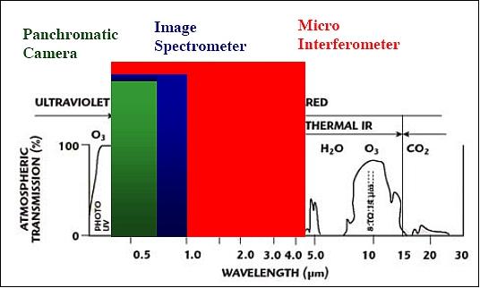
Pan Camera
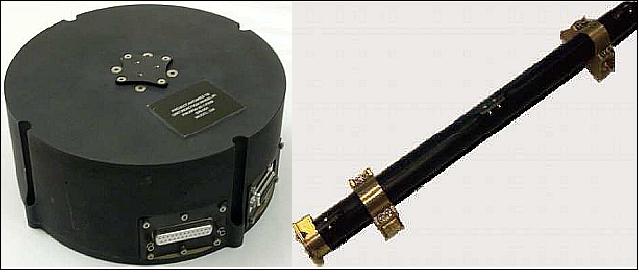
The objective of the Pan camera is to provide high resolution imagery at 2 m GSD (nadir). The imager will use an innovative telescope based on lightweight mirrors and an extensible structure which is an evolution of a previous ASI project called MITAR ((MIcroTelescope with a High Resolution).
Instrument type | Pushbroom imager for continuous observations in along-track |
Spectral range | 0.4 - 0.9 µm |
GSD (Ground Sample Distance) | 2 m (at nadir) |
Swath width | 10 km |
SNR (Signal-to-Noise Ratio) | > 200 |
MTF (Modulation Transfer Function) | 0.085 along-track; 1.2 cross-track direction |
Data quantization | 12 bit |
The most significant applications of the Panchromatic Camera are relevant to:
- Cartography (with 2 m GSD a map with the scale of 1:10.000 should be possible)
- Hydrology and coastal resources: boundary determination and monitoring
- Anthropic phenomena
- Support to environmental management in case of natural disasters
- Archeology (detection of archaeological sites)
- Emergency management.
ALISEO (Aerospace Leap-frog Imaging Stationary Interferometer for Earth Observation)
ALISEO is a Sagnac spectroradiometer, an imaging interferometer designed and developed at CNR/IFAC of Florence, Italy. This instrument has been derived from the so called "static interferometers", which do not employ any moving parts to optically scan the instrument field-of-view. 7) 8) 9) 10) 11) 12) 13) 14)
ALISEO acquires the imagery as modulated by a pattern of auto-correlation functions of the radiation energy coming from the observed scene. The complete interferogram of any target locations is observed introducing relative source-observer motion, which allows each pixel to be observed while going across the entire pattern of the EM (Electro-Magnetic) auto-correlation function.
Spectral range of instrument | 400 - 1000 nm |
Spectral resolution | Better than 5 nm @ 650 nm |
Image size, FOV (Field of View) | 10 km x 10 km, 1.15º |
Spatial resolution | 10 m |
Data quantization | 12 bit |
Detector | Silicon CCD 2D-array (1024 x 1024 elements) |
Expected SNR (Signal-to-Noise Ratio) | 200 @ 650 nm |
Data volume | 12.6 Mbit/image |
Instrument mass, | < 20 kg, |
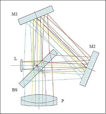
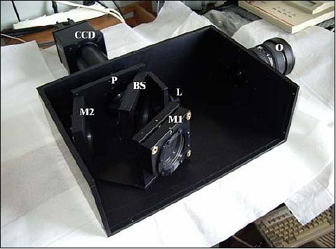
Radiation is collected from the objective L, then the two interfering rays are generated by the beam-splitter BS and travel the triangular ray path in opposite directions by means of two folding mirrors M1 and M2. The two rays are then focused onto the CCD by the camera lens P. It is easy to demonstrate that the BS is the fundamental component, which provides the basic phase-delay between the two coherent rays. Nonetheless, it can be shown that phase-delay is heavily affected by the overall instrument geometry: the BS to M1 and M2 distances and the orientation of the two folding mirrors. Figure 9 is a photo of the airborne prototype of ALISEO.
The Sagnac interferometer produces a fixed (stationary) pattern of interference fringes of equal thickness (Fizeau fringes). The OPD (Optical Path Difference) between the recombining beams linearly changes with the angle (slope) of the entering ray onto the instrument optical axis.
The instrument has no entrance slit; the device acquires the image of the target superimposed to a fixed pattern of interference fringes. Due to the relative sensor-object motion each target’s location crosses the entire interference pattern; hence, the corresponding pixel is observed under different phase delays when the scene is framed repeatedly in time - and the collected image sequence forms a 3-dimensional array of data, also referred to as image stack. This data cube is first processed to extract the complete interferogram of every target’s point; then it is cosine-inverse transformed to yield a hyperspectral data cube. The stack geometry is related to important characteristics of the sensor and the acquired data. For instance, the image sequence and target-sensor relative velocity govern the actual optical path difference between consecutive sample of a retrieved interferogram.
Possible applications of this imaging spectrometer are similar to those of the imaging spectrometers based on dispersive optics. The most relevant ALISEO applications are in the following fields:
- Geology: Identification and quantification of minerals and rocks
- Vegetation and agriculture: determination of vegetation indexes and of bio-geo-chemical parameters which characterize the vegetation status
- Coastal zone monitoring: determination of yellow substance and suspended sediments
- Desert blooms and wetland observations.
MZI (Mach Zehnder Interferometer)
The design of the MZI micro-interferometer is based on MOEMS (Micro Opto-Electro-Mechanical System) technology. The most relevant MZI applications are:
- Identification of aerosol and of main gaseous atmospheric components
- Correction of atmospheric effects
- Monitoring volcanic flow activities and ash plumes.
MZI has the following specification:
• Observation band: 0.4 - 4.5
• Spectral resolution: 1nm @ 650 nm
• Observation spot: 3 km (nadir looking)
• SNR: 500 @ 650 nm
• Data quantization: 16 bit
• Source data rate: 16 Mbit/s.
Spotlight observations: The microsatellite features an operational mode for spotlight observations - intended for ALISEO and Pan Camera instrument support. This mode permits the spacecraft to point into a specific target area for “extended observations” of a spot of interest thereby creating a TDI (Time Delay Integration) effect - which results in improved SNR values and ultimately in higher quality imagery.
Miniature Sun Sensor
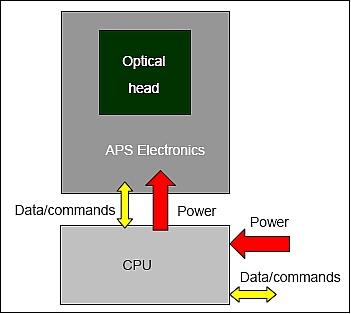
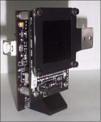
A prototype sun sensor is part of the AOCS. It is a miniature device developed by the University of Naples, Italy (funded by ASI). The photodetector used is a 2D CMOS APS (Active Pixel Sensor) of Micron Technology with a pixel array of 1280 x 1280 pixels. The sensor exploits an APS photodetector and a mask with tiny holes to produce sun images on the focal plane. An innovative sensor concept has been developed capable of providing multiple sun images on the focal plane. These images, once simultaneously processed and averaged, provide improved precision in the sun line determination. The device is capable of providing average (on the field of view) accuracy and precision of an order of 1 arcminute and 1 arcsecond, respectively.15) 16)
Optical head | |
Focal length | 3 mm |
FOV (Field of View) | 94º x 81º (1-hole mask) |
Mask | |
Material | Steel |
Thickness | 0.1 mm |
Number of holes | 1 / 100 (enhanced configuration) |
Hole diameter | 0.2 mm |
Holes’ arrangement (enhanced configuration) | 10 x 10 array, 0.42 mm pitch (both directions) |
Photodetector | |
Technology | CMOS Active Pixel Sensor (APS) |
Model | MT 9M001 by Micron Technology, Inc. |
Resolution | 1280 x 1024 pixels |
Pixel size | 5.2 µm x 5.2 µm |
Sensing area size | 6.66 mm x 5.32 mm |
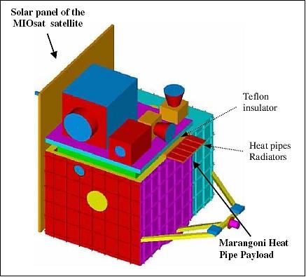
Heat Pipe Experiment
MIOSat will host a dedicated payload to investigate innovative heat pipes to be operated in space under a microgravity environment. For the comparative study, some heat pipes will be manufactured with a conventional metallic structure (copper or aluminum) and will be filled with ordinary and innovative working fluids. In particular, one of them will be selected as a reference heat pipe and charged with water or ammonia, representing the most common working fluids used in terrestrial or space heat pipes. The other heat pipes will be charged with binary or multi-component self-rewetting solutions with particular surface tension properties. Indeed, one of the primary objectives of the experiment is to show the advantages related to the reverse Marangoni effect, typical of suitable liquid mixtures with surface tension increasing with temperature (self-rewetting fluids). 17) 18)
In the experiment, one of the heat pipes will be an innovative flexible, inflatable and deployable ultra-light weight radiator panel in laminated/polyimide laminate filled with self-rewetting fluid.
Each heat pipe is independent and fixed to an aluminum base plate that will interface the satellite panels. The heat pipes will be selected with a diameter of 4–8 mm and a length of 250 mm. One of the heat pipes will be an innovative flexible heat pipe made of kapton.
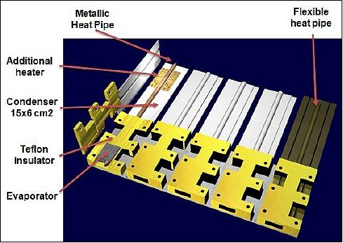
Heat will be supplied by cartridge heaters at the evaporator sections and dissipated at the condenser sections composed by aluminum radiators, whose frontal area is 15 cm x 6 cm. A high conductivity paste between the heat pipe and the condenser/evaporator sections will optimize the thermal contact between pipe and radiator. To maximize the power radiated by the radiators, a thin coat of white paint suitable for space applications will be applied over their surface.
The overall envelop of the heat pipe experiment is 300 mm x 350 mm x 30 mm, excluding the electronic housing box. The heat pipe experiment will be operated continuously for three orbital periods per day when the satellite is in sun-pointing attitude. The data will be stored by the OBDH and downlinked after the end of each experimental run during the following orbits in S-band. The overall data packet size is ~ 10 Mbit.
SSR (Space Software Receiver)
SSR is a new generation demonstration device and a low-cost modular space SW GNSS receiver of Intecs S.p.A., Pisa, Italy. The instrument is suitable to be embedded into a spacecraft OBC or in a special version to be implemented by FPGA. Microsatellites generally need limited performance in terms of orbit position knowledge in the order of 100 mt in the three axes. This value is compatible even with GPS data sampling and post processing in a CPU in combination with an orbit propagator. 19)
The instrument consists of three elements:
• the antenna (provided by the satellite bus)
• the connection cable between the antenna and the SSR unit
• the SSR unit.
The SSR is being controlled by the OBDH (On Board Data Handling) subsystem and powered by the PDCU (Power Distribution Control Unit). The SSR unit is composed of three boards:
• SIB (System Interconnection Board)
• SPB (System Power Board)
• SEB (System Elaboration Board).
SIB implements all interface structures between SPB, SEB, and the MIOSat OBC connector. The SPB receives through the SIB connector the main power bus of MIOSat (non-regulated 28 VDC) and converts it generating all voltages values needed for electronic components in SEB as well as the SPB filter incoming power and input/output data from the RS 422 transceiver. The SEB implements the GNSS signals elaboration and the PVT (Position, Velocity, Time) calculation.
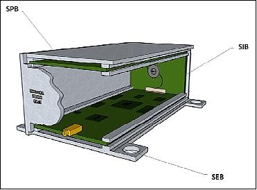
The SEB board is internally composed of: a front-end, in charge of down-converting, filtering, amplifying and sampling the input signal, TCXO (Temperature Compensated Crystal Oscillator) local oscillator direct connected to the front-end, the FPGA, in charge of performing basic time-consuming operations, part of acquisition and tracking logical modules. The Soft-CPU, wired inside FPGA, in charge of elaborating the output from the FPGA and resolving the PVT solution and some mass memory, Flash, SDRAM and SRAM.
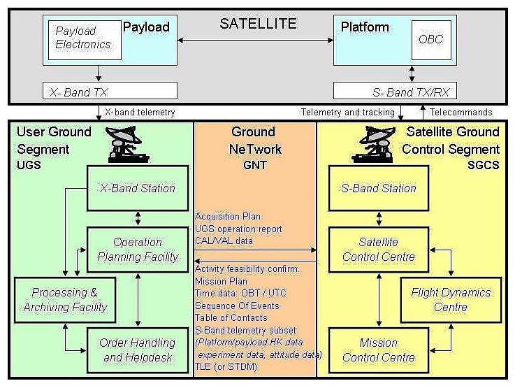
Ground Segment
The Ground Segment is composed by a SGCS (Satellite Ground Control Segment) and a UGS (User Ground Segment) that respectively manages satellite operations and user requests submission and products acquisition and delivery; the connection between the two segments is provided by the Ground NeTwork (GNT).
References
1) Cristina Agostara, Cesare Dionisio, Giuseppe Sgroi, Alessio di Salvo, “MIOSat mission scenario and design,” Proceedings of the IAA Symposium on Small Satellite Systems and Services (4S), Rhodes, Greece, May 26-30, 2008, ESA SP-660, August 2008
2) C. Agostara, C. Dionisio, A. Di Salvo, G. Guarrera, “MIOSat mission analysis and scenario definition,” European Workshop on Space Mission Analysis, ESA / ESOC, Dec. 10 –12, 2007, URL: http://flight-dynamics.esa.int/MA_Workshop_2007_Presentations/EO5_MIOSAT_mission_analysis.pdf
3) Cristina Agostara, Cesare Dionisio, Alessio Di Salvo, Giuseppe Guarrera, “MIOSat mission analysis and scenario definition,” European Workshop on Space Mission Analysis, ESA/ESOC, Darmstadt, Germany, Dec. 10-12, 2007
4) Cristina Agostara, Cesare Dionisio, Alessio Di Salvo, Giuseppe Sgroi, Giuseppe Guarrera, “MIOSat: An Italian Low-Cost Technological / Scientific Microsatellite,” Proceedings of the 59th IAC (International Astronautical Congress), Glasgow, Scotland, UK, Sept. 29 to Oct. 3, 2008, IAC-08.B4.2.6
5) http://www.asi.it/en/activity/earth_observation/miosat_
6) E. Razzano, T. Lupi, P. Sabatini, “Micro-Satellite Platform with Building-Block Approach for Leo Missions,” Proceedings of the Symposium on Small Satellite Systems and Services (4S), Funchal, Madeira, Portugal, May 31-June 4, 2010
7) Alessandro Barducci, Francesco Castagnoli, Guido Castellini, Donatella Guzzi, Cinzia Lastri, Paolo Marcoionni, Ivan Pippi, Matteo Viani, Cesare Dionisio, Giuseppe Sgroi, “The ALISEO Payload For The Small Technological Mission MIOSAT,” Proceedings of the 7th IAA Symposium on Small Satellites for Earth Observation, Berlin, Germany, May 4-7, 2009, IAA-B7-0305P
8) A. Barducci, F. Castagnoli, G. Castellini, D. Guzzi, P. Marcoionni, I. Pippi, “ALISEO on MIOSAT: An Imaging Interferometer for Earth Observation,” Proceedings of the 7th ICSO (International Conference on Space Optics) 2008, Toulouse, France, Oct. 14-17, 2008, URL: http://www.icsoconference2008.com/cd/pdf/S21%20-%20Spectrometers%20-%20Pippi.pdf
9) A. Barducci, F. Castagnoli, G. Castellini, D. Guzzi, P. Marcoionni, I. Pippi, “The Aerospace Imaging Interferometer ALISEO: Further Improvements of Calibration Methods and Assessment of Interferometer Response,” 21st ISPRS (International Society for Photogrammetry and Remote Sensing) Congress,Beijing, China, July 3-11, 2008, URL: http://www.isprs.org/proceedings/XXXVII/congress/1_pdf/161.pdf
10) V. de Cosmo, “Imaging Spectrometer Developments in Italian Space Agency,” Proceedings of the 7th ICSO (International Conference on Space Optics) 2008, Toulouse, France, Oct. 14-17, 2008, URL: http://www.icsoconference2008.com/cd/pdf/S22%20-%20Spectrometers%20-%20De%20Cosmo.pdf
11) A. Barducci, F. Castagnoli, D. Guzzi, P. Marcoionni, I. Pippi, “The aerospace imaging interferometer ALISEO: further improvements of calibration methods and assessment of interferometer response,” Proceedings of the SPIE, 'Sensors, Systems, and Next-Generation Satellites XI,'. Edited by Roland Meynart, Steven P. Neeck, Haruhisa Shimoda; Shahid Habib, Volume 6744, 2007, pp. 67441J
12) Alessandro Barducci, Francesco Castagnoli, Vittorio De Cosmo, Donatella Guzzi, Paolo Marcoionni, Ivan Pippi, “ALISEO: An Imaging Interferometer on Microsatellite for Earth Observation,” Proceedings 5th EARSeL Workshop on Imaging Spectroscopy, Bruges, Belgium, April 23-25 2007, URL: http://5thearselsigis.vgt.vito.be/CD/Fullpapers/Barducci_final.pdf
13) Alessandro Barducci, Vittorio De Cosmo, Paolo Marcoionni, Ivan Pippi, “ALISEO: a new stationary imaging interferometer,” Proceedings of SPIE, 'Imaging Spectrometry X,' Vol. 5546, Aug. 2-6, 2004, Denver, CO, USA, DOI:10.1117/12.557191
14) V. Nardino, D. Guzzi, I. Pippi, “Developing of the ALISEO Sagnac Interferometer Optical Configuration,” URL: http://ieee.uniparthenope.it/chapter/_private/proc10/20.pdf
15) Giancarlo Rufino, Michele Grassi, “Multi-Aperture CMOS Sun Sensor for Microsatellite Attitude Determination,” Sensors, Vol. 9, 2009, pp. 4503-4524, doi:10.3390/s90604503, URL: http://www.mdpi.com/1424-8220/9/6/4503/pdf
16) G. Rufino, M. Grassi, M. Rolfi, “Preliminary Calibration Results For a High-Precision CMOS Sun Sensor,” AIAA Guidance, Navigation and Control Conference and Exhibit, August 18-21, 2008, Honolulu, Hawaii, USA, AIAA-2008-7319
17) Raffaele Savino, Anselmo Cecere, Roberto Di Paola, Yoshiyuki Abe, Dario Castagnolo, Raimondo Fortezza, “Marangoni heat pipe:An experiment on board MIOSat Italian microsatellite,” Acta Astronautica, Vol. 65, 2009, pp. 1582-1592
18) Anselmo Cecere, Raffaele Savino, Antonio Moccia, “A study on self-rewetting fluids for heat transfer in microgravity,” URL: http://www.fedoa.unina.it/3829/1/Cecere_Anselmo.pdf
19) Luca Cucchi, Cesare Dionisio, Riccardo Marracci, Gabriele Pirazzi, “GNSS SW receiver for space applications,” Proceedings of NAVITEC 2008, 4th ESA Workshop on Satellite Navigation User Equipment Technologies GNSS User Technologies in the Sensor Fusion Era, Dec. 10-12, 2008, Noordwijk, The Netherlands
The information compiled and edited in this article was provided by Herbert J. Kramer from his documentation of: "Observation of the Earth and Its Environment: Survey of Missions and Sensors" (Springer Verlag) as well as many other sources after the publication of the 4th edition in 2002. - Comments and corrections to this article are always welcome for further updates (eoportal@symbios.space).