MINISAT Program
Initiatives and Programs
MINISAT
MINISAT is a national space program of Spain, funded by the Inter-Ministerial Committee of Space Science and Technology (CICYT) and by INTA, supported by the Center for the Development of Industrial Technology (CDTI), and managed by INTA (National Institute for Aerospace Research). The program started in 1990 with first feasibility studies, the design phase was initiated in 1993. The major objectives of the program are to develop a national (INTA, industry, academia, and private sector) capability and to create an environment for state-of-the-art space age technology and research - to mobilize human resources. The emphasis is an affordable technology in the minisatellite and microsatellite segments, along with all the associated activities for all phases of successful space missions. 1) 2) 3)
The first stage of the MINISAT program concluded with the development and qualification of the MINISAT-0 platform. Phase A of MINISAT-01 started in 1995. - The MINISAT-1 modular satellite family of the program is dedicated mainly to LEO EO mission applications. The third stage of the MINISAT program, the MINISAT-2 family, is an adaptation of the MINISAT-1 family for GEO mission applications. 4)
MINISAT-01
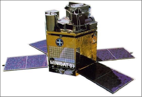
MINISAT-01 is an INTA satellite (platform built by CASA, payload built by INTA), comprised of a low-cost multipurpose bus with a payload consisting of three experiments and a technology demonstrator. The science objective of the mission is the study of background radiation in the extreme ultraviolet spectrum, low energy gamma radiation, and the behavior of liquid bridges in microgravity. The S/C consists of a service module (or bus) and a payload module (payloads up to 300 kg can be accommodated in the architecture). The satellite measures 1145 mm x 1005 mm x 1170 mm and has four deployable solar AsGa panels (each 60 W, size of 550 mm x 800 mm). The spacecraft average power requirement is 60 W. A NiCd battery is used for energy provision during eclipse times of the orbit. 5) 6) 7) 8) 9)
MINISAT-01 is a sun-pointing, momentum-bias (spin) stabilized satellite with a capability to convert to a 3-axis stabilized one by employing torque rod control (three orthogonal torque rods and one momentum/reaction wheel as actuators for attitude control). The pointing accuracy is ±3º. The attitude is sensed by two two-axis magnetometers and two coarse sun sensors with overlapping FOVs.
The thermal subsystem uses heaters, thermistors, thermal blankets and paints. Most of the spacecraft is using a passive thermal subsystem, only the battery and the payload include heaters and control loops to maintain their temperature within margins.
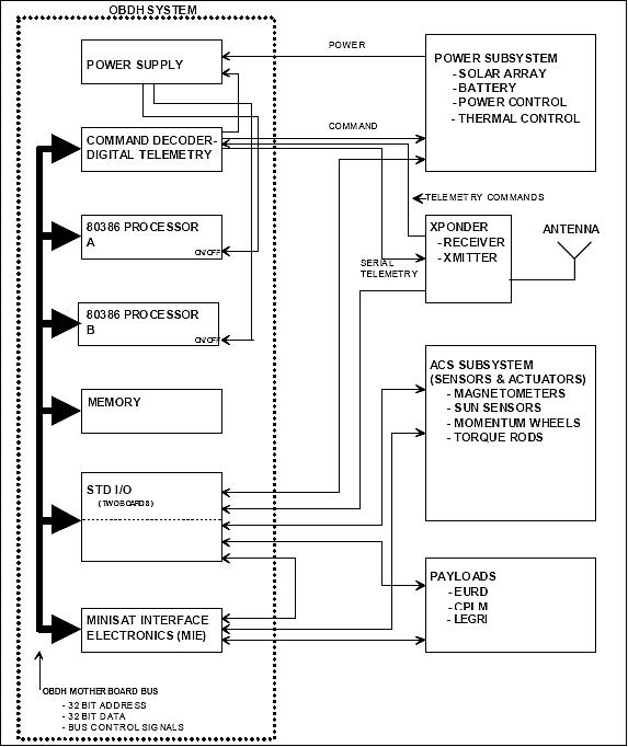
The OBC (Onboard Computer) is a centralized system, based on an Intel 80386 microprocessor, with point-to-point interfaces to all subsystems. The throughput is 2.4 MIPS using cache memory. The OBC provides 32 MByte of RAM memory for scientific data, 512 kByte of EEPROM to store the flight code and the default software control tables; 512 kByte of RAM with EDAC is used to store the command data. The CPU is configured in cold redundant mode; just one CPU is operative at any time.
The spacecraft bus has a mass of 105 kg, payload mass is 90 kg (total mass of 195 kg). The design life is 4-5 years.
RF communications: Uplink and downlink communication is via S-band, 5W transmitter/receiver at 1 Mbit/s, the on-board data storage capability is 32 MByte. The uplink data rate is 2 kbit/s.
Launch
The S/C was air-launched on a Pegasus-XL vehicle from the Canary Islands (Spain) on April 21, 1997. MINISAT-01 is operated by INTA and tracked via the Maspalomas ground station (15º 37' 45” W, 27º 45' 49” N).
Orbit: Near-circular orbit, apogee = 585 km, perigee = 566 km, inclination =151º (29º retrograde), period =96 minutes.
Mission Status
• MINISAT-01 reentered the atmosphere on Feb. 14, 2002 after almost 5 years working in orbit with remarkable scientific results and an outstanding performance of the spacecraft. 11)
Sensor Complement
The MINISAT-01 modular design philosophy allowed the independent integration of the platform (bus) and the payload, and couple them together afterwards. In fact, the platform was integrated at CASA while the payload module (PLM) was integrated at INTA. The PLM contains the scientific instruments EURD, CPLM and LEGRI and the common subsystems: structure, thermal control and harnessing. The other subsystem functions, power, onboard data handling, attitude control and TT&C are provided by the platform. 12) 13)
EURD (Espectrógrafo Ultravioleta extremo para la observación de la Radiación Difusa - Extreme UV Spectrograph for the Study of Diffuse Radiation)
EURD was designed and developed by INTA and UCB (University of California at Berkeley). The objectives are to conduct spectrographic observations of the diffuse EUV region of radiation, to study the nature of the interstellar medium, the airglow in the upper atmosphere (atomic oxygen and oxygen lines), and to search for dark matter in the form of massive (about 10 eV), long lived (> 1024 s) neutrinos.
The instrument employs two spectrometers. An important feature of these spectrometers is their ability to identify or eliminate systematic effects that have compromised previous efforts to detect diffuse UV radiation. Each spectrometer is equipped with a filter wheel at its entrance slit, which is stepped through four operating positions to evaluate internal background, glare, starlight, and true interstellar plasma emission. These positions include an open position transmitting all wavelength, a metal shield that blocks all radiation and provides a measurement of the internal background, a magnesium fluoride filter giving a measurement of the Lyman alpha radiation, and an aluminum filter that transmits most of the EUV radiation and strongly blocks any scattered Lyman alpha radiation. The EURD instrument is observing continuously during eclipse periods with the S/C pointing into the anti-sun direction. 14)
Spectral band | 300-1050 Å |
FOV | 26º x 8º |
Grating | 8 cm diameter, 18 cm focal length, holographically ruled 2460 lines/mm |
Grating overcoat | long wavelength: silicon carbide; short wavelength: boron carbide |
Detector | Multichannel Plate (MCP) with wedge and strip encoding |
Detector photocathode | long wavelength: chemically treated; short wavelength: magnesium fluoride |
Size (each spectrograph) | 40 cm x 40 cm x 13 cm |
Mass (each spectrograph) | 11 kg |
CPLM (Column of Liquid Bridge in Microgravity)
CPLM (Comportamiento De Puentes Líquidos En Microgravedad) was developed at the Polytechnic University of Madrid. Objective: to study the behavior of axis-symmetric liquid bridges in microgravity conditions. Accelerations are induced by satellite maneuvers. The CPLM instrument consists of the following components mounted inside a cylindrical container: a test cell with a liquid bridge cell, optical detectors to measure the liquid bridge deformation, motor control to allow the liquid bridge formation and the modification of the liquid bridge configuration trough its length, an accelerometer unit to measure the accelerations supported by the liquid bridge, a power supply unit to deliver the appropriate voltages to the different subsystems, a temperature sensor to monitor the CPLM temperature, and pressure sensors to monitor the pressure in the test cell and outside of the test cell. The liquid bridge is oriented perpendicular to the z axis (sun to satellite direction) and also to the z spin rate direction. It means when the satellite is spinning from -0.375 to +0.375 rpm some axis-symmetric accelerations are induced in the liquid bridge. CPLM is operating about once per week (5 minute cycle). 15)
LEGRI (Low Energy Gamma Ray Imager)
LEGRI was developed by a Spanish/British team from the University of Valencia, INTA, CIEMAT, Birmingham University, and RAL (Rutherford Appleton Laboratory). The objective is to demonstrate the technological feasibility of a new generation gamma-ray telescope detector design optimized for low-energy radiation (in the energy range of 10 - 200 keV), using solid-state crystals as detector elements. The actual measuring objective is to detect the gamma-ray radiation emitted by various galactic sources such as neutron stars, binary systems, black hole candidates, and active galactic nuclei. 16)
The initial LEGRI imaging array design employed 100 HgI2 detectors, a new and emerging detector material, providing an excellent response in the 10-200 keV energy range, with the best presently achieved efficiency/volume ratio. In addition, the material works efficiently at room temperature and exhibits a very high resistance to radiation damage. CIEMAT (Centro de Investigaciones Energéticas y Medioambientales - Environmental and Energetic Research Center) has been working on this material, a production line for such detectors is under development.
The final imaging array design consists of 80 HgI2 by 20 CdZnTe detectors. The intent is to compare the performances of both detector types, using the same FEE and working under the same background fluxes. - LEGRI is observing in the day part of the orbit mainly and in whatever direction perpendicular to the sun direction.
The LEGRI instrument consists of the following elements:
• A detector unit, comprising a detector plane formed by an array of 80 HgI2 and 20 CdZnTe elements, the associated front end electronics and a mechanical collimator, all within a mechanical assembly acting as a passive shield.
• A mask unit, located at 540 mm from the detector plane and parallel to it, consisting of a coded mask made by tungsten elements on a honeycomb plate and a support structure.
• A power supply and digital processing units, which act as direct interfaces to PLM for power and data transmission.
• A high voltage supply unit, which provides the high voltages needed to operate the detectors.
• A start sensor, which is used to determine precisely and continuously the attitude of the satellite, allowing for the reconstruction on ground of the gamma-ray images without spatial blurring caused by platform drift or jitter.
ETRV (Experiencia Tecnológica de un Regulador de Velocidad - Speed Regulator Technology Demonstrator)
ETRV was developed by CASA. ETRV is a mechanical speed regulator and deployment mechanism intended to deploy in the future such items as antennas, panels, and booms. The instrument consists of the following elements: a motor and torsion spring; gears to reduce the speed; a momentum wheel to simulate the deployable structure; a pyrotechnic nut to maintain the configuration from launch to the time to fire the pyro and to deploy the dummy mass (momentum wheel); a magnetic Reed switch to measure the angular movement of the momentum wheel and it rates; and associated electronics to manage all the signals. - For the technology demonstration, the speed regulator ETRV must deploy the momentum wheel at a constant rate and with a total deployment angle of 180º in 180 seconds.
References
1) Paper provided by M. A. Garcia Primo of INTA
2) M. A. Garcia Primo, “Spanish MINISAT Program - Objectives and Operational Results,” Proceedings of the 4th International Symposium on Small Satellites Systems and Services, Sept. 14-18, 1998, Antibes Juan les Pins, France
3) “MINISAT-01,” URL: http://www.inta.es/doc/programasaltatecnologia/minisatelites/inta_t1_1.pdf
4) F. Cerezo Martinez, “ MINISAT-01 (One Year After),” Proceedings of the 4th International Symposium on Small Satellites Systems and Services, Sept. 14-18, 1998, Antibes Juan les Pins, France
5) V. Reglero, “MINISAT-01: Hybrid satellite for science and technology,” Advances in Space Research, Volume 31, No 2, 2003 , pp. 331-339
6) Alvaro Gimenez, “MINISAT-01 as a scientific mission and its future,” Astrophysics and Space Science, Vol. 276, pp. 13-19, 2001
7) Fernando Cerezo Martinez, “Performances of MINISAT-01 Platform Subsystems,” Astrophysics and Space Science, Vol. 276, pp. 31-38, 2001
8) J. Pérez Diestro, F. Cerezo Martínez, B. Garrido Gómez, A. García García, “Sppain's MINISAT-01 On-Board Data Handling Subsystem and On-Board Software,” URL: http://www2.dem.inpe.br/ijar/dasia96.pdf
9) “The MINISAT Project,” URL: http://ipl.uv.es/?q=es/content/page/minisat-project
10) D. Guzman,M. Angulo, L. Seoane, S. Sanchez, M. Pietro, D. Meziat, “Overview of the INTASAT's Data Architecture Based on SpaceWire,” International SpaceWire Conference, Dundee, Scotland, Sept. 17-19, 2007, URL:. http://spacewire.computing.dundee.ac.uk/proceedings/Presentations/Missions and Applications 1/guzman.pdf
11) D. Garcia-Asensio, M. Perez-Ayucar, M. A. Serrano, “MINISAT 01, Concept and Evolution in the Operations of a Successful Small Mission,” Proceedings of the 18th International Symposium on Space Flight Dynamics (ESA SP-548), Munich, Germany, Oct. 11-15, 2004
12) J. Torres, R. Alfageme, “Development of MINISAT-01 Scientific Payload,” Astrophysics and Space Science, Vol. 276, No 1, January 2001, pp. 21-29
13) V. Reglero, “MINISAT-01: Hybrid satellite for science and technology,” Advances in Space Research, Volume 31, Issue 2, 2003, pp. 331–339
14) Carmen Morales, Joaquin Trapero, Jose F. Gomez, Veronica Orozco, Alvaro Gimenez, Stuart Bowyer, Jerry Edelstein, Eric Korpela, Michael Lampton, Jeff Cobb, “EURD: The Mission and the stellar absolute fluxes of B-Type stars,” Astrophysics and Space Science, Vol. 276, pp. 141–150, 2001, URL: http://setiathome.berkeley.edu/~korpela/papers/eurd_bstars.pdf
15) Angel Sanz-Andrés, Pablo Rodríguez-De-Francisco, Julian Santiago-Prowald, “The Experiment CPLM (Comportamiento De Puentes Líquidos En Microgravedad) On Board MINISAT-01,” Astrophysics and Space Science, Vol. 276, Issue 1, 2001, pp. 97-121
16) Julia Suso, Pere Blay, Robert Almudena, Victor Reglero, Chris J. Eyles, “LEGRI instrument health. A historical review,” Astrophysics and Space Science, Vol. 276, Issue 1, 2001, pp. 299-309
The information compiled and edited in this article was provided by Herbert J. Kramer from his documentation of: ”Observation of the Earth and Its Environment: Survey of Missions and Sensors” (Springer Verlag) as well as many other sources after the publication of the 4th edition in 2002. - Comments and corrections to this article are always welcome for further updates (eoportal@symbios.space).