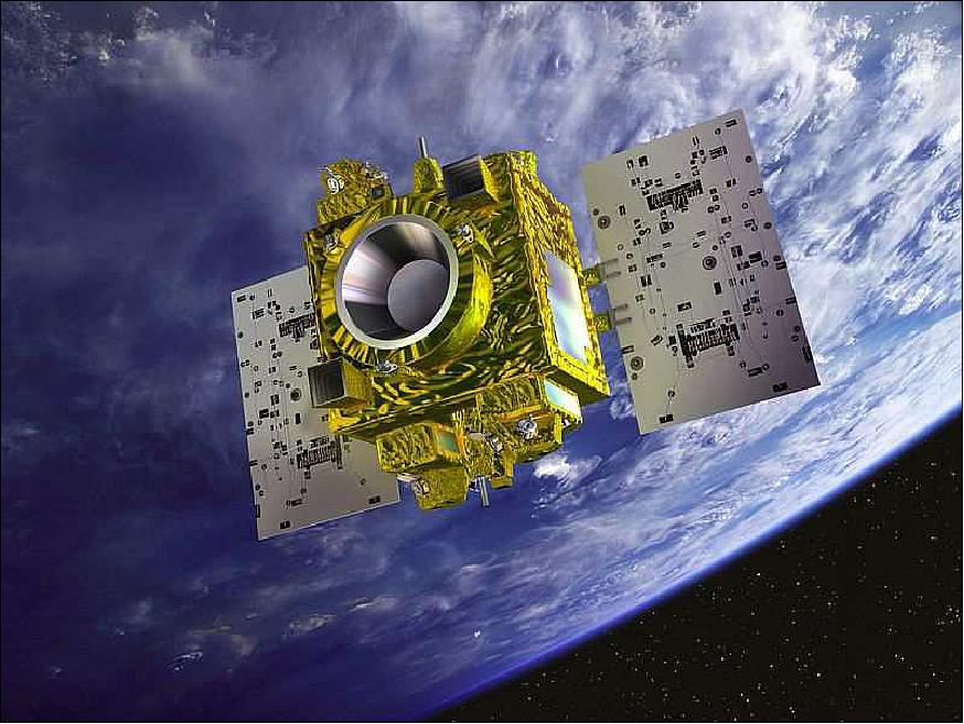
MicroSCOPE (Micro-Satellite à traînée Compensée pour l'Observation du Principe d'Equivalence)
EO
Mission complete
CNES
The Microsatellite with Compensated Drag for Observing the Principle of Equivalence (MicroSCOPE) was a collaboration between the French institutions CNES (National Centre for Space Studies), ONERA (National Office for Aerospace Studies and Research) and OCA (Côte d'Azur Observatory), and the German organisations PTB (Physikalisch-Technische Bundesanstalt) and the ZARM laboratory of the University of Bremen. The objective was to conduct a fundamental physics experiment, namely testing the Weak Equivalence Principle (WEP), so as to probe Einstein’s general theory of relativity. Between its launch in April 2016 and its end of life in October 2018, the mission successfully tested the WEP to an accuracy of the order of 10-14.
Quick facts
Overview
| Mission type | EO |
| Agency | CNES |
| Mission status | Mission complete |
| Launch date | 25 Apr 2016 |
| End of life date | 30 Oct 2018 |
| CEOS EO Handbook | See MicroSCOPE (Micro-Satellite à traînée Compensée pour l'Observation du Principe d'Equivalence) summary |
Summary
Mission Capabilities
The Twin-Space Accelerometer for Gravity Experiment (T-SAGE) was the main scientific instrument on the satellite, consisting of two cylindrical concentric electrostatic differential accelerometers, each of which featured two proof masses suspended in a highly stable electrode cage. The sum of all the forces acting on the test masses, including Earth’s gravitational pull, was maintained to a null value by the satellite drag compensation system, while the thrusters of the electric propulsion system acted to move the instrument’s silica frame following the masses along the orbital path. A possible WEP-violating signal could have been detected from the difference between the electrostatic forces required to maintain the positions of the two proof masses at the centre of the instrument cage.
Performance Specifications
MicroSCOPE benefited from an ulta-stable thermal environment, in particular around the frequency fep, which is the frequency of excitation of the equivalence principle. Thus, at this frequency, the FEEU (Front End Electric Units) interface was thermally stable within 10 mK, the SU (Sensor Unit) interface was thermally stable within 1 mK, while the angular and linear accelerations of T-SAGE were accurate to 1%.
The experiment showed no deviations from the Equivalence Principle up to an accuracy of 2 x 10-14, still confirming Einstein's General Relativity Theory and constraining alternative theories to new limits.
MicroSCOPE maintained a sun-synchronous quasi-circular dawn-dusk orbit at an altitude of 710 km and an orbital inclination of 98.18°.
Space and Hardware Components
The spacecraft bus of MicroSCOPE was part of the Myriade microsatellite series of CNES, having a box-like honeycomb-and-plate structure, although heavier and larger than the standard.
The Drag-Free Attitude Control System (DFACS) was the attitude actuator and measurement system of the mission, providing accurate measurements of the spacecraft accelerations with six degrees of freedom. Replacing the Myriade generic Attitude and Orbit Control System, DFACS was able to operate in five modes, out of which the Acceleration Control Mode was specific to MicroSCOPE. It allowed the WEP measurement by providing linear acceleration control with a very high accuracy, in addition to the traditional three-axis attitude control of the Myriade series. DFACS employed a Cold Gas Propulsion System (CGPS), operated on a continuous basis.
Attitude sensing is provided by sun sensors, a three-axis magnetometer, and a star-tracker in the anti-sun direction.
Thanks to IDEAS (Innovative DEorbiting Aerobrake System), MicroSCOPE will be able to abide by the "Space Debris Code of Conduct" rule, re-entering and burning in the Earth’s atmosphere within about 25 years.
MicroSCOPE
Spacecraft Launch Mission Status Sensor Complement Ground Segment References
MicroSCOPE (Micro-Satellite à traînée Compensée pour l'Observation du Principe d'Equivalence) is an approved CNES/ESA gravity-research minisatellite mission, put forward in 2000 by ONERA (Office National d'Etudes et de Recherches Aérospatiales), Châtillon, France, and by OCA (Observatoire de la Côte d'Azur) in Grasse, France. The mission is a collaboration between CNES, ZARM laboratory (University of Bremen), PTB (Physikalisch-Technische Bundesanstalt) of Braunschweig, Germany, OCA and ONERA. 1) 2) 3)
The objective is to conduct a fundamental physics experiment, namely to test the general theory of relativity. This concept is also known as the WEP (Weak Equivalence Principle) test. The WEP postulates a perfect proportionality between the inertial mass and the gravitational mass of a body. A direct consequence of this Equivalence Principle is the `universality of free fall' such that all objects fall with exactly the same acceleration in the same gravity field. EP turned out to be a major principle of Albert Einstein's general theory of relativity, formulated in 1907 and in 1911.
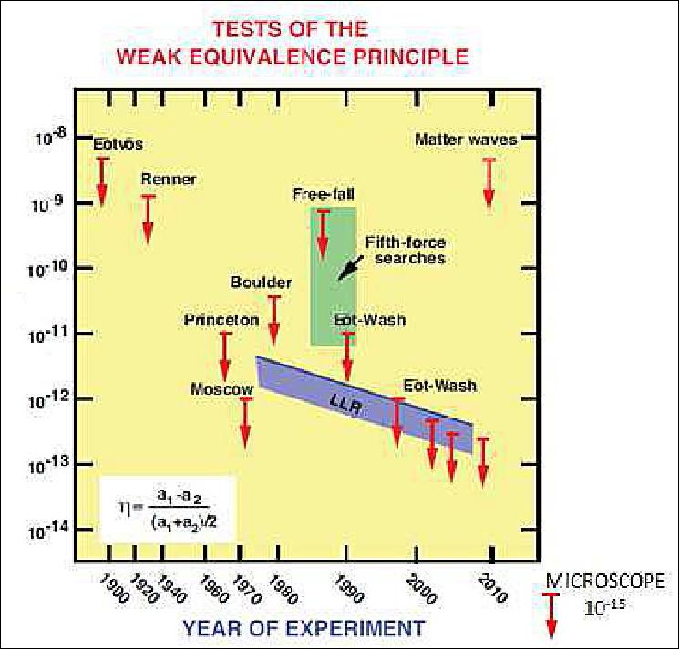
The microscope mission concept to test EP is similar to the original STEP (Satellite Test of the Equivalence Principle) mission design of 1989 (a NASA/ESA proposal that wasn't realized). The major simplification of MicroSCOPE is the use of a room-temperature instrument (instead of a cryogenic payload operating at 2 K for STEP). - The best accuracy value of the EP achieved by experiments on Earth is 10-13, the MicroSCOPE mission wants to improve this value by two orders of magnitude to 10-15.. Leading-edge technologies are implemented, these include: ultra-sensitive accelerometers, ionic thrusters, and simultaneous spin control and drag-free systems. 4) 5) 6) 7) 8) 9) 10) 11) 12) 13) 14)
The mission performance relies on very high technologies not yet tested all together: full 3-axes and continuous drag-free satellite control, the hybridization of star sensor and accelerometer measurements for attitude control, micro-newton (µN) cold gas thrusters, milli-Kelvin (mK) passive thermal control of the payload, inflight calibration, and a femto-g accurate electrostatic differential accelerometer for the payload.
In the overall organization, CNES is the lead agency in charge of the microsatellite (system, test and integration) and the S/C operations. ESA is responsible for the procurement of the FEEP thrusters. Mission and data analysis functions are performed in close collaboration with ONERA and OCA (Observatoire de la Côte d'Azur)/GEMINI. The ZARM (Center for Applied Space Technology and Microgravity) of Bremen, Germany is contributing to the project (assisting with accelerometer qualification testing in their drop tower and drag-free system analysis) through DLR funding. 15)
Note: In the text as well as in the various references, the spelling of the terms "MicroSCOPE" and "Microscope" are being used freely with the same meaning.
Main Satellite/Payload Design Challenges and Requirements
The MicroSCOPE satellite plays the role of a space laboratory devoted to a very complex experiment of physics, and for this it must point the instrument on 3 axis, protect it against non-gravitational forces, and ensure an ultra-stable thermal environment, in particular around the frequency fep which is the frequency of excitation of the equivalence principle.
On the other hand, the restricted funding of the mission that belongs to the CNES Myriade program does not allow to develop specific satellite equipment or to make complex choices of architecture.
• First of all, the reduction of the mean level of applied forces on the instrument introduces a new function: the acceleration control (referred to as drag-free control). Since there is no better instrument than an inertial sensor to measure the external forces, this function uses SAGE (Space Accelerometer for Gravitation Experimentation) as sensor.
- On the other side of the process, a very fine actuator is needed to counteract the perturbations (atmospheric drag, radiation pressure, electromagnetic forces) the mean value of which is not higher than some tens of µN. MicroSCOPE will use a proportional micro propulsion system which is being based on the FEEP (Field Effect Electrical Propulsion) principle.
- The FEEP thrusters are grouped in 4 Electrical Propulsion System Assemblies (EPSA, Figure 20). The combination of the six degrees of freedom (attitude and linear acceleration) in one function leads create a new subsystem, called AACS (Attitude and Acceleration Control Subsystem). The attitude and drag-free control requirements call for motion reduction noises as low as 10-12 ms-2 Hz-1/2 (i.e., accelerometer resolution) — to obtain a test resolution of better than 10-15.
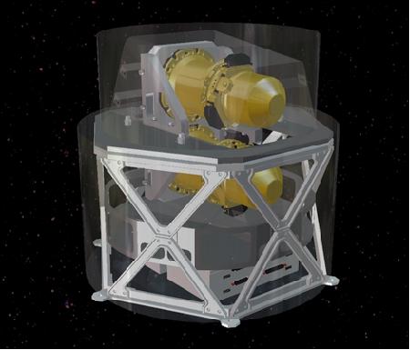
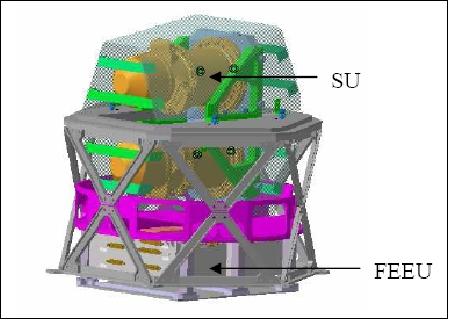
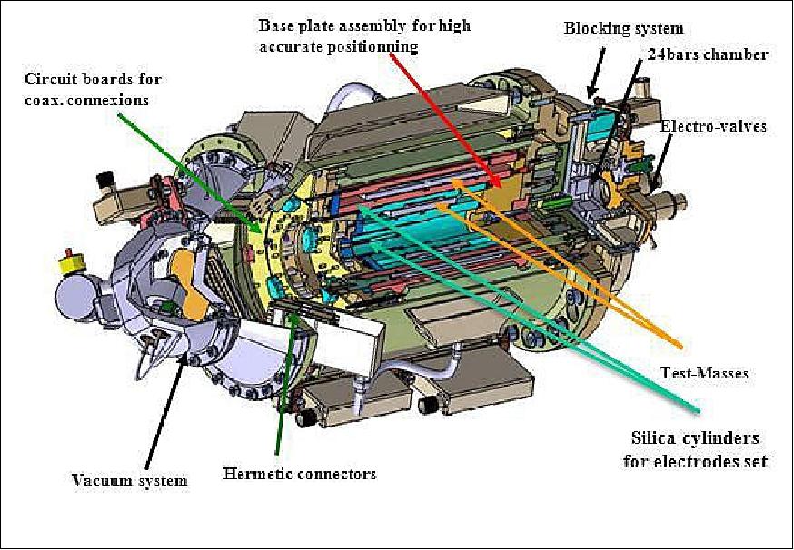
• A second major design driver is the need to have the satellite mass center close to each of the 4 proof masses of the instrument: therefore a set of two sensor units (SUs) are chosen along with the corresponding FEEUs (Front End Electric Units) in a payload structure which is inside the satellite structure.
- The payload position inside the satellite puts severe requirements on the mechanical, and moreover on the thermal design, induced by the thermal sensitivity of the instrument: the required stability around fep is 1mK at SU interface, 10 mK at the FEEU interface.
• A third design driving point is the need to guarantee an ultra-stable dynamic environment to the instrument. The requirement on the attitude rate stability in rotating mode around fep is equivalent to a requirement in attitude stability of the instrument better than 0.166 µrad at a very low frequency. As this order of magnitude is far below the thermoelastic deformation between the instrument plate and the measurement axes of every kind of attitude sensors that can be laid out, it is clearly a challenging requirement for the AACS.
• Finally, the mission requires to reduce or calibrate any kind of dynamic perturbation on the proof-masses, combined with the position of the payload inside the satellite structure and thus close to the platform equipment, create another category of drivers in the architecture: the reduction of internal micro-perturbations. There are three dominating categories of perturbations: a) mechanical (direct forces due to matter displacement), b) gravitational (change of the induced gravity gradient when the satellite shape changes), and c) magnetic (resulting from the electrical activity in the satellite circuits and equipment).
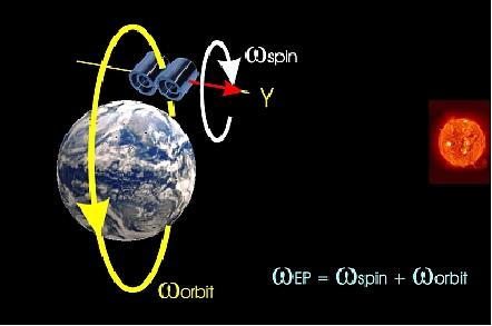
In the MicroSCOPE experiment, the Earth is the gravitational source about which free fall motion of two masses, composed of different materials, is observed and controlled taking care that both masses are submitted exactly to the same gravitational field. The controlled electrostatic field, added to break the experimentation symmetry by forcing the masses to remain on the same orbit is accurately measured: a defect of symmetry gives rise to evidence of an EP violation.
Due to the noise level of the best current ultra-precise accelerometers (10-12 ms-2 Hz-1/2), the aimed accuracy of the test can only be achieved by filtering the signal over a long period of time Ti. Typically there will be two modes:
• Inertial mode: Ti = 120 orbits; fep ≈ 1.7 x 10⁻⁴ Hz
• Rotating mode: Ti = 20 orbits; fep ≈ 1.0 x 10⁻³ Hz
Spacecraft
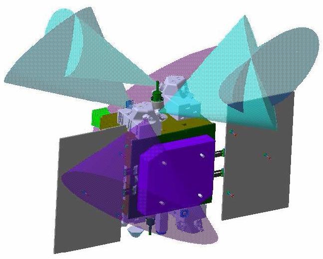
The Myriade series microsatellite bus of CNES is being used (of DEMETER and PARASOL heritage). The microsatellite bus consists of a box-like honeycomb-and-plate structure. Lateral panels are assembled by four L-spar support structures, and can be opened independently during integration. The Z panels are dedicated to CGPS (Cold Gas Propulsion System), and the Y panels accommodate the rest of the equipments except Star Tracker Optical Heads which are located on the –X wall as close as possible of the PAS (Payload Assembly Subsystem) in order to allow a good natural alignment stability of Star Tracker measurement axes with respect to the instrument spin axis. 17)
The design of Myriade (actually a minisatellite in this implementation) is a compromise between high performance, efficiency, robustness and cost. The architecture of the satellite is based on a platform with generic functional chains (AOCS, Energy, Communication, Computer, Structure, Thermal Control), and on a decoupled payload located on the upper part of the platform structure.
The solar array (AsGa cells) with an area of 1.6 m2 consists of two deployed panels, providing a power of 140 W (shared between the electric propulsion system, the instrument and the S/C bus). Particular attention is paid to the thermo-elastic behavior of the S/C as well as to possible magnetic disturbances to the test masses.
The satellite is either spin-stabilized with the spin axis directed normal to the orbit plane - or inertially (3-axis) stabilized. The main functions of the AACS (Attitude and Acceleration Control Subsystem) are to:
- To control the attitude of the spacecraft
- To control the linear accelerations of the satellite (drag compensation)
- To produce the linear and angular excitations of the satellite which are necessary for instrument calibration.
Attitude sensing is provided by sun sensors, a 3-axis magnetometer, and a star tracker (in the anti-sun direction). Attitude actuation and drag compensation is provided by DFACS (Drag-Free Attitude Control System) as described below in the sensor complement. In addition, actuation may be provided by magnetorquers and reaction wheels (when needed like in the orbit injection phase).
The AACS uses the scientific instrument (SAGE) as a sensor for angular and linear accelerations. In mission mode, the only other attitude sensor is a star tracker, µASC (micro Advanced Stellar Compass) of DTU (Technical University of Denmark) with two optical devices, i.e. with two CHU (Camera Head Units).
MicroSCOPE is bigger and heavier than the standard Myriade product line. The S/C mass budget is about 303 kg (hence, MicroSCOPE is a minisatellite), the mission design life is one year. The thermal control of the minisatellite is performed entirely by passive methods.
The external layout (Figure 5) is mainly constrained by antennas accommodation and AACS equipment I/F requirement in order to minimize the modifications with respect to AOCS standard non-mission modes. For centering and symmetry reasons, the solar generator is separated in two identical wings of one panel each, mounted on Y panels and directed toward +X. During launch, the wings are folded; the release is provided by 3 pyrolock mechanisms and the deployment by 2 Carpenter blades. These components are already used on the standard Myriade product line. Solar array driving mechanisms are not needed due to the good energy budget of the dawn/dusk orbit.
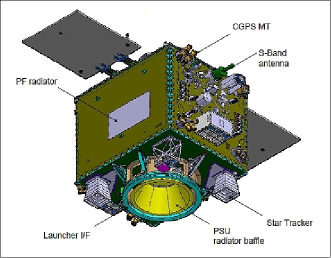
Payload interface concept: A specific PAS (Payload Assembly Subsystem) has been defined (Figure 6) to achieve the temperature stability requirements of SU and FEEU. PAS is the structure supporting the SU and the FEEU, it includes also the thermal control hardware. The requirements of PAS shall:
- Allow the centering of proof masses with respect to the satellite spin axis
- Offer a very high mechanical stability during the entire mission
- Provide a thermal stability to SU better than 2 mK at fep (peak to peak value)
- Protect the SU from magnetic perturbations
- Guarantee the thermal control of FEEU (10:45ºC operating range and taking into account their 6 W power dissipation each).
The PAS is mounted on the anti-sun panel of the satellite (-X) to take advantage of the high natural external flux stability of this side along the 6 hour local time orbit, and to avoid thermal cycling from Earth's radiative flux. The PAS is made of a two-stage structure. The FEEUs are centered on the first stage where thermal stability requirements is a sinus of half amplitude 10 mK at fep.
The accelerometer sensor units (SUs) are centered on the second stage by four brackets where thermal stability requirement is ten times better (less than 1 mK at fep)), so that the first stage thermal stability can be used for pre-regulation. Radiative insulation of the PAS is achieved using MLI (Multi Layer Insulation). The total mass of the PAS approaches 50 kg, and the volume is 54 cm in diameter by 50 cm in height.
Equipment layout: The internal equipment layout is based on three main considerations: mass symmetry, thermal symmetry, and thermal stability. The PAS is located in the center of the spacecraft and equipment masses are balanced on the four lateral panels to have the PAS spin axis close to the satellite center of mass. Dissipations of equipment are balanced on opposite lateral panels (±Ys) so that external fluxes absorbed by the radiators at fep are in phase opposition. Hence, the resulting conductive thermal flux at the PAS interface is minimized. Equipment with lower thermal dissipation loads are fixed on the other panels with poor thermal rejection capacity. The deorbiting system is located on the +Xs panel and deployed at the end of the mission.
Minisatellite mass, power | 330 kg, ~ 140 W |
Overall volume deployed | 138 cm (X) x 2470 cm (Y) x 155 cm (Z) |
Centering of instrument spin axis w.r.t. center of mass | < 5 mm |
Main inertia axis along the X axis | 40 kgm2 |
Thermal stability @ fep on FEEU interface | < 10 mK |
Thermoelastic stability @ fep star tracker / instrument | < 12 µrad in inertial mode |
RF communications: The functional chain is the S-band communication link of the Myriade product line with a data rate of 625 kbit/s. The on-board solid-state recorder has a capacity of 1 Gbit (the total source data rate, including housekeeping data, is about 1 kbit/s). The spacecraft operations are conducted at CNES. The science mission center is at ONERA.
Status of Project Development
• October 2015: The ICUME was the last unit submitted in environmental tests, the acceptance review is fulfilled and the ICUME has been delivered in May 2015. 19)
- The integration of the all elements of the instrument into the satellite is now achieved and environmental test of the satellite are undergone.
- A good health test sequence has been established in order to asses the integrity of the instrument when integrated into the satellite and during the environmental test of the satellite. It consists in verifying as far as possible the functionality of the SU, FEEU and ICUME knowing that the instrument is in a pre-launch configuration ie with the test masses blocked in their electrostatic cage.
- The MICROSCOPE payload has undergone a long development process due to its high accuracy and its high technology most of the time at the limits of the state of the art. Thanks to the pertinacity of the team, ONERA is proud to deliver to CNES the best accelerometer ever realized in the world: the best instrument to sense the Equivalence Principle, one of the most essential principles of the standard Physics.
- The instrument is now integrated into the satellite that is subjected to the environmental tests, one of the last steps before to the launch on Soyuz board as a passenger in April 2016.
• The SU (Sensor Unit) and the FEEU (Front End Electronics Unit) have passed successfully the qualification and acceptance tests. They should be delivered to CNES in September 2014 in order to be integrated in the payload box of the microsatellite. 20) 21)
- The ICUME (Interface Control Unit Mechanical Ensemble) is the last unit to be tested in environmental tests, and the acceptance review is foreseen at the beginning of 2015.
• March 2014: Satellite CDR (Critical Design Review) and CGPS and performances key point: the Steering Committee on May 15th authorized the beginning of the satellite AIT (Assembly, Integration and Tests).
• The T-SAGE (Twin Space Accelerometer for Gravitation Experiment) has been integrated all along 2013 and 2014. Due to the difficulty to operate the instrument on ground and the very high accuracy of the sensors only achievable in orbit environment, a specific validation has been implemented. It relies on the validation of each unit separately.
• In the spring of 2011, the project advanced to Phase B.
• The MicroSCOPE PDR (Preliminary Design Review) was held in March 2011. 22)
The long time spent between these dates is justified by a major change in the propulsion system (initial propulsion system using FEEP (Field Effect Electric Thrusters) has been replaced by cold gas thrusters requiring a considerable rebuilt of the satellite.
During this time, the development of the payload kept on through several EMs (Engineering Models). The qualification model of SU has been manufactured (Figure 24); the qualification campaign started in December 2010 and it is scheduled to end before the end of 2011.
• The MicroSCOPE project approval was given in 2004.
Launch
The MicroSCOPE minisatellite was launched as a secondary payload onboard a Soyuz vehicle (VS 14) on April 25, 2016 (21:02:13 UTC) from Kourou. The primary payload was the Sentinel-1B spacecraft of ESA. 23) 24) 25) 26)
Secondary payloads of Sentinel-1B: 27)
• MicroSCOPE, a minisatellite (303 kg) of CNES (French Space Agency) which will test the universality of free fall.
• AAUSAT4, a 1U CubeSat of the University of Aalborg, Denmark.
• e-st@r-II (Educational SaTellite @ politecnico di toRino-II), a 1U CubeSat from the Polytechnic of Turin, Italy.
• OUFTI-1 (Orbital Utility for Telecommunication Innovation), a 1U CubeSat of the University of Liège, Belgium.
Tyvak International installed the three CubeSats in the orbital deployer. The three CubeSats are part of ESA's FYS (Fly Your Satellite) student program.
Orbit: Sun-synchronous quasi-circular dawn-dusk orbit, altitude ~710 km, eccentricity = 5 x 10⁻³, inclination = 98.18º, LTAN (Local Time on Ascending Node) = 6:00 hours or 18:00 hours. The low eclipse dawn/dusk orbit is chosen to maintain the payload in a very stable thermal environment.
Note: The nominal altitude of MicroCOPE (~693 km) is a compromise between several factors, among which mainly the need of the highest possible gravity signal (favored by low orbits) and the minimization of the atmospheric drag and other perturbations (better if the orbit is higher).
Mission Status
• October 18, 2018: CNES teams have achieved a first with the innovative passive deorbiting of the Microscope satellite (MICROSatellite à trainée Compensée pour l'Observation du Principe d'Equivalence) after its two-year science mission and six months of valuable technology experiments. 28)
- Microscope's mission has come to an end with the depletion of the nitrogen fuel reserves needed for the satellite's precise control microthrusters. Without this fuel for its drag-compensation system, the satellite is no longer able to deliver science data.
- Operations to passively de-orbit Microscope without expending fuel, performed by teams at the Toulouse Space Center since the start of this week, have proved especially innovative. They began by passivating the satellite to make it safe for deorbiting and ensure that no source of chemical, pneumatic or electrical energy will pollute outer space. The next key step in the sequence involved deployment of IDEAS (Innovative DEorbiting Aerobrake System), a system designed by CNES consisting of two 4.5 m inflatable booms wrapped in membranes to increase the satellite's atmospheric drag surface area. It is the use of these booms in the real-life conditions of space that makes this passive de-orbiting sequence particularly innovative and unique. Thanks to this system, Microscope should reenter and burn up in Earth's atmosphere in approximately 25 years' time, as required by the French Space Operations Act (FSOA) effective since 2008. The estimated time it would have taken Microscope to reenter the atmosphere had the IDEAS system not been used was 73 years.
- Microscope is thus the first operational satellite to be deorbited in this way. Its retirement from service illustrates CNES's commitment to mitigating pollution and the proliferation of space debris in LEO (Low Earth Orbit).
- After the success of this delicate deorbiting phase, CNES President Jean-Yves Le Gall commented: "CNES's teams have again demonstrated their know-how and expertise in passively deorbiting Microscope, which is a truly remarkable feat. It follows this mission's unprecedented scientific success in applying an innovative operational technology to verify the equivalence principle. The Microscope science teams are continuing to analyze all of the data collected by the mission and their results are expected at the end of next year."
• October 2018: Launched in April 2016, the satellite of the MICROSCOPE space mission should end its operations in autumn 2018. The science objective is the test of the WEP (Weak Equivalence Principle) with an accuracy of 10-15. The EP is one cornerstone of GR (General Relativity); it states the equivalence between gravitational and inertial mass. Most of the alternative quantum gravity theories or the extensions of GR have to confront this founding principle. In 2017, MICROSCOPE's first results settled a new frontier of the EP lower than 2 x 10-14 with only 10% of the available data. Since then, all data are available and are being analyzed to accomplish the primary objective. 29)
- The in-orbit test is based on the comparison of the acceleration of two cylindrical bodies in free-fall around the Earth at 710 km altitude. The two bodies are the test-masses of two concentric electrostatic accelerometers which constitute the science payload of the satellite. The acceleration measurements are also used by the satellite drag compensation and the attitude control system. This system embarks cold gas thrusters which are capable of micronewton thrusts in order to maintain the payload case free of surface forces like the atmospheric residual drag or the solar pressure disturbances but also free of the disturbing torques (mainly magnetic or gravitational torques).
- In summary, the WEP has been tested in orbit with MICROSCOPE to an unprecedented accuracy of a few 10-14. This experiment still confirms Eintein's theory of Gravitation and constraints alternative theories to new limits.
- The in orbit mission should end on 16 October 2018. But the data process will go on until 2019.
- The final result is foreseen to be published at end of 2019 with very good expectation of improvement of the current results. This should constrain the physics model of gravitation to level never achieved before.
• December 2017: According to the WEP (Weak Equivalence Principle), all bodies should fall at the same rate in a gravitational field. The MICROSCOPE satellite, launched in April 2016, aims to test its validity at the 10-15 precision level, by measuring the force required to maintain two test masses (of titanium and platinum alloys) exactly in the same orbit. A non-vanishing result would correspond to a violation of the Equivalence Principle, or to the discovery of a new long-range force. Analysis of the first data gives δ(Ti; Pt) = [-1±9 (stat) ±9 (syst)] x 10-15 (1 σ statistical uncertainty) for the titanium-platinum Eötvös parameter characterizing the relative difference in their free-fall accelerations. 30)
- Gravity seems to enjoy a remarkable universality property: bodies of different compositions fall at the same rate in an external gravitational field. Einstein interpreted this as an equivalence between gravitation and inertia, and used this (Weak) Equivalence Principle (WEP) as the starting point for the theory of General Relativity.
- In terms of the Eötvös parameter δ(A; B) = 2(aA - aB)/(aA + aB) with (aA and aB being the free-fall accelerations of the two bodies A and B), the best laboratory (1σ) upper limits on δ(A; B) are δ(Be; Ti) = (0:3±1.8) x10-13 and δ(Be; Al) = (-0.7±1.3) x 10-13[ 31)], with similar limits on the differential acceleration between the Earth and the Moon toward the Sun.
- General Relativity (GR) has passed all historical and current experimental tests [32)], including, most recently, the direct observation of the gravitational waves emitted by two coalescing black holes. 33)
- However, it does not provide a consistent quantum gravity landscape and leaves many questions unanswered, in particular about dark energy and the unification of all fundamental interactions. Possible avenues to close those problems may involve very weakly coupled new particles, such as the string-theory spin-0 dilaton [34), 35)], a chameleon [36)] or a spin-1 boson U from an extended gauge group [37), 38)], generally leading to an apparent WEP violation.
- In summary, the project presented the first results on MICROSCOPE's test of the Weak Equivalence Principle with conservative upper limits for some errors. Nevertheless this result constitutes an improvement of one order of magnitude over the present ground experiments (Ref. 31). Forthcoming sessions dedicated to complete the detailed exploration of systematic errors will allow the project to improve the experiment's accuracy. Thousands of orbits of scientific measurements should be available by the end of the mission in 2018. The integration over longer periods of the differential accelerometer signal should lead to a better precision on the WEP test. MICROSCOPE will certainly take a step forward in accuracy, closer to the mission objective of 10-15 and bring new constraints to alternative gravity theories.
• September 2017: Microscope constitutes the first high accuracy Equivalent Principle test made in space. Whatever the results on EP violation or not, it will help the scientific community to go forward in the understanding of fundamental physic laws. The Scientific Mission is running since December 2016; publication of the first scientific in-flight results should be done before the end of 2017. 39)
• December 7, 2016: Six months after launch, the Microscope minisatellite has completed its in-orbit checkout. To accomplish its mission to test the equivalence principle with unprecedented precision, the satellite has to compensate in all directions for all forces acting on it other than gravity, like residual atmospheric drag (Microscope is orbiting Earth at an altitude of 710 km) and pressure exerted by sunlight. 40)
- The measured performance of the compensation system is already proving exceptional, making the CNES satellite a new world benchmark in LEO (Low Earth Orbit). The instrument, comprising two differential accelerometers, supplied by the French aerospace research agency ONERA, is so sensitive that it has been able to detect the gravity-gradient effect of a displacement of the proof masses of no more than a few micrometers, and the variation in pressure exerted by sunlight during a partial eclipse by the Moon. - The proof mass control system is so precise that it is able to maintain their relative position to within the width of a hydrogen atom—one millionth that of a human hair.
- New science phase begins: The science phase of the mission has now begun and will last for at least 18 months to obtain the most precise measurements possible. A first performance status check is planned for June 2017 and final results will be published no later than April 2019 to validate science data processing.
• September 27, 2016: Microscope has been in orbit since 26 April 2016 and teams at CNES and the French aerospace research agency ONERA are conducting final tests before switching the satellite into mission mode. During this in-orbit checkout phase, they have been testing and adjusting the satellite and verifying the performance of its instruments, which have already accomplished two remarkable feats: 41)
- The differential accelerometers supplied by ONERA have been able to clearly observe the predicted gravity gradient effects due to the relative motion of the two proof masses. This gravity gradient corresponds to the difference in the pull exerted by Earth's gravity on the inner mass and outer mass housed inside the T-SAGE instrument. During tests, the accelerometers were able to measure a difference of 25 µm for one of the masses and 33 µm for the other, the equivalent of half the thickness of a human hair.
- A further demonstration of the instruments' extreme precision was provided when the satellite was able to measure and compensate for the force exerted not by Earth's gravity but by sunlight. On 1 September, the Moon eclipsed 15% of the Sun's surface and Microscope was able to detect the eclipse four times as it circled Earth. These partial eclipses produce a variation in the forces acting on the satellite equivalent to the weight of a small grain of sand. These measurements prove the instrument's sensitivity and the precision of its drag-compensation system.
• May 2016: From April to mid June 2016, the commissioning phase should state on the good heath of the satellite and all its subsystems including the payload developed by ONERA and the drag-free controller. From June to end of July 2016, the satellite will be in pause because of a period of eclipses. At end of July, the satellite will be awaken with the payload. Then, the science should start with ideal thermal conditions for nine months. After preliminary performances tests, the calibration phase will be performed and then the EP tests in several configuration of the satellite (inertial pointing, two rotation frequencies of the spin). 42)
- In January 2017, a first science Phase should be completed and give a first taste of violation or not. The performance of the experiment and the evaluation of the bar of systematic errors should be available in 24 months to consolidate the levels of 10-15 sensitivity.
• April 26, 2016: The launch of Sentinel-1B went according to plan; the spacecraft was placed into its orbit (altitude = 693 km) 23 minutes and 35 seconds after launch (launch mass of 2164 kg). Sentinel-1B is the fourth in a series of Sentinel satellites for the European Copernicus program, a joint project of the EC (European Commission) and ESA (European Space Agency).
Deployment sequence of the secondary payloads: 43) 44)
- The trio of "Fly Your Satellite!" student-built CubeSats were released into space at 23:50 GMT (2 hours 48 minutes after liftoff). Transmissions from the Fregat upper stage show that the door on the CubeSat deployer opened regularly, around 2 hours and 48 minutes after launch. Now the CubeSats are travelling in their final orbits, and their university teams are waiting for them to establish contact. - In the first hour of flight, the CubeSats will be working autonomously in order to stabilize their motion, perform an internal health check, and deploy their antennae. Then they will establish communication with Earth.
- The CubeSats were deployed into an elliptical orbit of 665 km x 453 km. From this orbit they will re-enter Earth's atmosphere in approximately 8 years, preventing they become space junk after their missions are over.
- The MicroSCOPE minisatellite of CNES was the last deployment in the launch sequence at 01:02 GMT (4 hours into the flight) on April 26.
Sensor Complement
The objective of the EP test is to expose two test masses to the same gravitational force to see if they are both affected in the same way. This, of course, requires concentric masses, with their centers of mass precisely aligned. However, as they cannot be idealized point masses, they will in fact be affected by the local gravity gradient.
Experiment principle: The experiment consists in controlling the free fall motions of two quasi-cylindrical masses made of different materials on the same orbit inside a dedicated satellite. They are subjected to the same gravitational field. To achieve this in the variable field of Earth's gravity, two restrictions are placed on the accelerometer design: the masses must be concentric to share a common center of gravity, and the shape of the masses must be chosen so that the gravity gradient effects are analogous on the two masses. 45) 46) 47) 48) 49) 50) 51) 52) 53) 54) 55)
The satellite constitutes for the experimental masses a shield from the atmospheric drag and from the Sun and Earth radiation pressures. It carries a specific electrical propulsion system to compensate these surface forces and to follow the masses.
T-SAGE (Twin-Space Accelerometer for Gravity Experiment)
SAGE is the differential accelerometer designed and developed by ONERA/DMPH (Département Mesures Physiques), Châtillon, France. SAGE consists of a set of two cylindrical concentric electrostatic differential accelerometers designed and developed at ONERA. The SAGE design is of STAR and SuperSTAR (Super Space Three-axis Accelerometer for Research mission) heritage, flown on the CHAMP and the GRACE missions, respectively. The combination of the two differential accelerometers (SAGE-EP and SAGE-REF) constituting the scientific instrument is also referred to as T-SAGE for Twin-SAGE due to the fact that it consists of two differential accelerometers.
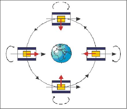
An electrostatic accelerometer consists, fundamentally, of a proof mass (PM) suspended in a highly stable electrode cage. The principle of operation is to measure the electrostatic forces required to maintain the position of the proof mass with respect to the electrodes. The proof or test mass of each accelerometer is maintained along the three orthogonal axes at the center of the fused silica instrument cage by electrostatic forces. Electrodes, engraved in the cage wall, are used for the capacitive sensing of the mass position and attitude. Both test masses are controlled with respect to the cage frame: the sum of the forces is maintained to a null value by the satellite drag compensation system; the thrusters of the electric propulsion system act to move the instrument silica frame following the masses. The difference of the electrostatic forces is then observed in the orbital path for the search of the EP-violating signal. The electrode configuration allows six-degree-of-freedom measurements and control of each test mass.
Rotational axis of S/C | About any axis ( all axes x, y, z, are identical) | |
| Max value at DC | Stability at fep |
Angular velocity | 10-6 rad/s, [or 3.9 and 4.9 x10⁻³ rad/s (spin)] | 10-6 rad/s Hz-1/2 |
Angular acceleration | 2 x 10⁻⁶ rad s-2 | 2 x 10⁻⁸ rad s-2 Hz-1/2 |
Linear acceleration | 3 x 10⁻⁸ ms-2 | 3 x 10⁻¹⁰ ms-2 Hz-1/2 |
In the case of SAGE, two inertial sensors are positioned to give their proof-masses the same center of gravity, to form one differential accelerometer. To obtain such a configuration the masses are cylindrical, with carefully machined dimensions, to approximate spherical moments of inertia, to reduce the gravity gradient disturbing effects.
When considering a perfect instrument, the measurement of a difference in the acceleration of two concentric test mass in a perfect Earth geodetic gives the evidence of the Equivalence Principle violation. Indeed when orbiting around the Earth the two concentric test masses see the same gravity and thus by equivalence the same acceleration independently on their mass or composition.
However nothing is perfect and one has to consider the machining and integration accuracy of the parts that will lead to a relative miss-centering of the two masses. If 20 µm miscentering is considered, the gravitational effect on the measured acceleration is of more than 8 x 10-15 ms-2 for only one contributor. Obviously the test mass centering is calibrated in orbit with 0.1 µm accuracy helping to reject by a factor 200 this contributor. Nevertheless, on ground a centering of 20 µm along all axes has to be performed.
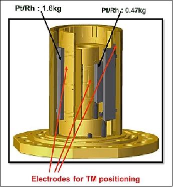
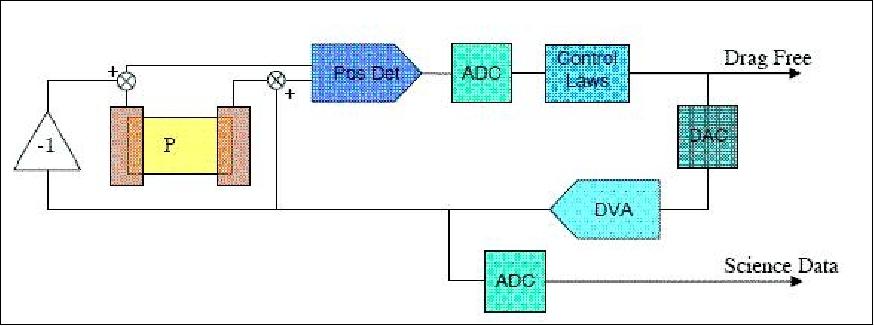
As shown in Figure 13, the centering of test masses is ensured by electrostatic positioning. The same electrodes serve for the position detection through capacitive sensing at 100 kHz and for the positioning through applied voltages on electrodes. The applied voltages are calculated by a digital controller (Digital Signal Processor TMS21020) taking into account the six degrees of freedom of each test mass. Thus, the test masses are servo-controlled to be motion less with respect to the electrode setting seen as the reference frame.
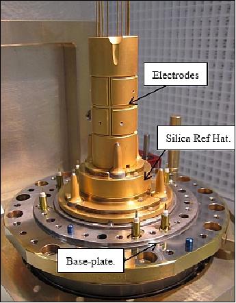
The 4 cylinders of the electrode set are placed on a gold-coated silica reference ‘Hat' as in Figure 14. Then the relative centering of the two test-masses of each sensor unit depends on the quality of the assembly.
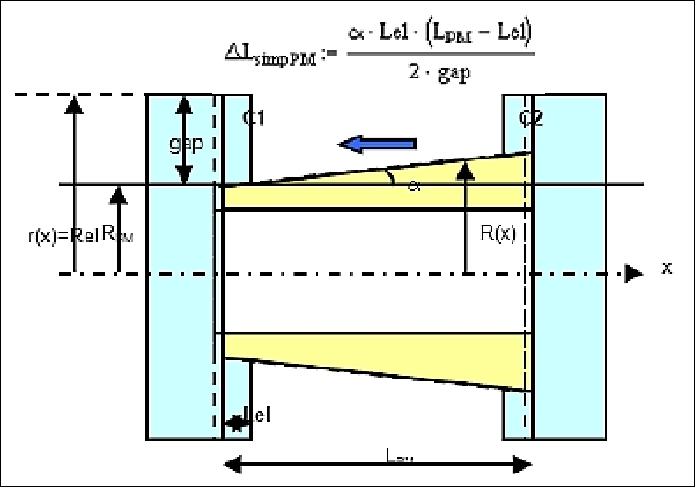
The servo-control of the test mass works on the principle of balancing the capacitances for each degree of freedom. In the Figure , the balancing of the capacitances C1 and C2 used for the X control will induce a displacement of the test-mass along X proportional to the cone angle. This particular effect is also considered in addition to the machining accuracy of the electrode set and the reference ‘Hat'.
The two differential accelerometers on the satellite are identical except for the material of their masses. The instrument providing the science baseline (proof mass) has both masses in platinum-rhodium, while in the EP test instrument has the external mass in titanium and the internal in platinum-rhodium. The titanium mass has a nominal length of 79.9 mm, outer radius of 35 mm, and mass of 0.364 kg, while the smaller platinum mass has nominal dimensions of 43.51 mm in length, 20 mm in outer radius, and a mass of 0.473 kg.
Two differential accelerometers in SAGE:
• Two masses of identical material (PtRh) for test accuracy verification
• Two masses of different material (PtRh/TA6V) for the EP test.
The two inertial sensors are concentric coaxial cylinders, with a common center of mass between the two proof masses. The cylinder axis corresponds to the sensitive measurement axis (X). Each mass is maintained centered in six degrees of freedom by means of electrostatic forces from a surrounding cage of electrodes in gold-coated silica. The only physical contact between the mass and its surrounding cage is a 5 µm diameter gold wire, which is necessary to maintain its electrical charge stable, and also applies a high frequency voltage used for the capacitive position sensing.
The electrodes, working in pairs, are used for both displacement detection, by differential capacitive measurement, and position control, by electrostatic force actuation. Position sensing and actuation are designed to be linear along the instrument sensitive axis, the cylinder axis, in such a way to permit fine frequency signal analysis of the data.
The SAGE instrumentation consists of three components: (SU, FEEU, and ICU)
• SU (Sensor Unit) core = differential accelerometer, consisting of:
- Two SUMI (SU on a Mechanical Interface)
- Each SU = 2 test masses centered to 20 µm
- 1 mass corresponds to 1 inertial sensor (defines measurement frame)
Each SU comprises the concentric pair of test masses which motion is to be compared along the orbit travel. The masses are surrounded by a silica core, graved and gold coated to provide the necessary electrodes for the electrostatic control. The entire core is enclosed in a tight housing performing 10-5 Pa vacuum to minimize the residual parasitic forces on the masses like the radiometer effect or the outgassing.
• FEEU (Front End Electronics Unit) which contains the low noise analog electronics required for proof mass levitation, including the ADCs (Analog Digital Converters), DACs (Digital Analog Converters), and position sensors. There is 1 FEEU for each SU.
Each FEEU includes the capacitive sensing of the pair of masses, the reference voltage sources and the analog electronics to generate the electrical voltages applied on the electrodes. Each FEEU is associated to one SU. Associated to the SU in a thermal "cocoon", the thermal environment provided by the satellite is a few mK for the FEEU and a fraction of 1 mK at orbital frequency for the SU. This helps to provide very steady voltages and operation conditions for the measurements.
• ICU (Interface Control Unit) which contains the remaining electronics for SU operation, specifically the proof mass position control loop, as well as the systems for general experiment control and the satellite interface. The components are:
- 1 ICU for each FEEU (2 stacked together)
- 1 DSP (Digital Signal Processor) + 2 FPGA (Field Programmable Gate Array) for test mass control laws and data conditioning for the OBC (Onboard Computer)
- 2 Power Control Units (1 redundant) to convert the sat 28 V to stable secondary voltages (±45 V, ±15 V, +5 V, 3.3 V)
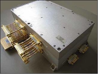
Both ICUs are integrated into a common device called ICUME (Interface Control Unit Mechanical Ensemble) as shown in Figure 19, providing the interface with the spacecraft.
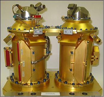
Both differential accelerometer cores are integrated in tight vacuum housings with thermal insulation and magnetic shielding provided. The instrument temperature variation is < 0.1º C per orbit. The entire instrument is positioned at the center of mass of the spacecraft to reduce any torque demand onto the electric propulsion system. The sensitive axes of the accelerometer are oriented in the orbital plane of the S/C x-axis, with the center of the test masses on the rotating axis of the S/C (normal to the orbital plane). The total instrument mass is 40 kg, the power is 20 W for each of the differential accelerometers.
Operations of the accelerometers: After all initial tests and calibrations, the EP experiment is realized with the first differential accelerometer in inertial and spinning attitudes and with two angular phases along the orbit. The test is concluded with a calibration. The same procedure is repeated with the second differential accelerometer. 56)
DFACS (Drag-Free Attitude Control System)
The mission requirements have several consequences on the satellite design. The spacecraft must protect the payload from all nongravitational forces perturbing the EP measurement; hence, an active control of accelerations and attitude of satellite is necessary to reach the required background level of acceleration.
The MicroSCOPE documentation provides several names for this control system. There is the designation DFACS as well as AACS (Acceleration and Attitude Control System).
DFACS is the attitude actuator and measurement system of the MicroSCOPE mission providing accurate measurements of the spacecraft accelerations in 6-DoF (Six Degrees of Freedom). DFACS employs a CGPS (Cold Gas Propulsion System).
Note: The initial design of DFACS (aka AACS) featured a FEEP (Field Emission Electric Propulsion)-type system -to be developed by Alta S. p. A. of Pisa, Italy. However, in 2009, the FEEP system was replaced by CGPS, developed by CNES with a major ESA contribution; its design is mainly based on the MPS (Micro Propulsion System) of ESA's GAIA mission, developed by TAS-I (Thales Alenia Space-Italia), Ref. 22). 57)
DFACS modes of operation
In the MicroSCOPE mission, the AACS (Attitude and Acceleration Control System) replaces the Myriade generic AOCS (Attitude and Orbit Control System) because the the real-time acceleration control of satellite is performed instead of the orbit control. However the two systems are very similar.
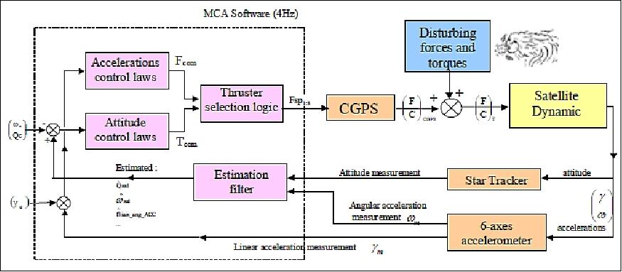
The AACS architecture is based on five modes (Figure 27):
• MLT is the launch mode, all the equipments are off.
• MAS (MicroSCOPE Acquisition & Safe-hold) mode. MAS employs the following attitude sensors and actuators (magnetometer, sun sensors, magnetorquers, reaction wheel) to obtain a stable sun-pointing attitude autonomously. MAS corresponds to the Myriade product line standard acquisition / safe mode.
• MGT2 (MicroSCOPE Geomagnetic Transition mode). MGT2 is a transition mode from acquisition to normal mode providing a coarse pointing. The attitude guidance is conical and rotating with a pro-grade spin rate of 2 ϖo (the satellite makes one revolution per orbit in an orbital frame). The control is based on the measurement of the magnetic field and its comparison with the on-board model.
Note: Normally, the Myriade series spacecraft (DEMETER, PARASOL, etc. ) spin at the orbital frequency providing a geocentric pointing, whereas MicroSCOPE spins at twice the orbital frequency (that is what the "2" of MGT2 stands for), with a roll bias.
• MSP (MicroSCOPE Stellar and Propulsion) mode, specific to MicroSCOPE only. Its control loop uses the star tracker as sensor, the CGPS thrusters as actuators, and three software functions (attitude and angular rate filter, control, command distribution). It has three functions:
- Ensure a transition from MGT2 to mission pointing in MCA (inertial or spinning)
- Allow technological operations (such as testing the instrument, or perform a maneuver to avoid the moon blooming in the star tracker)
- It constitutes an intermediate safe mode from MCA in case of an anomaly due to the instrument.
• MCA (Acceleration Control Mode). This drag-free mission mode is specific to MicroSCOPE allowing the EP measurement. Its main objective is to provide linear acceleration control, with a very high accuracy (10-12 ms2 residual acceleration at fep), in addition to the Myriade series traditional 3-axes attitude control. Figure 28 illustrates the control loops in MCA mode:
- Linear measures provided by SAGE are directly sent to the controller while the angular measures are introduced in the control loop after hybridization with star tracker measurements
- In MCAi (inertial) the attitude command is inertial, while in MCAs (spin) there is a commanded rate of 5 x 10⁻³ rad/s around the X-axis.
- MCAc is the calibration mode in inertial coordinates. Instrument calibration (scale factors and common-to-differential modes coupling, as well as FEEP calibration) is being conducted by sequentially commanding a low-frequency (0.005 Hz) sine excitation one each DoF.
The main issue is the quality of attitude measurements at fep. While the target is 0.166 µrad of attitude stability at fep on SAGE, the thermoelastic distortion of the platform between SAGE and the µASC (star tracker) is typically 5 µrad.
The DFACS system performance was already assessed and verified in a simulator, conducted by Astrium SAS, France.
Note: the terms AACS, and DFACS are being used in various papers to define all the same thing.
AACS (Acceleration and Attitude Control System), aka DFACS. AACS is used to suppress the non-gravity forces applied to the test masses. Due to the extreme precision required by the mission, this drag-free control system shall provide the satellite with very high performances in particular in the frequency of the EP check (fep). The AACS uses the inertial sensor unit's acceleration measurements (which is also the scientific instrument) and CGPS micro-propulsion.
CGPS (Cold Gas Propulsion System)
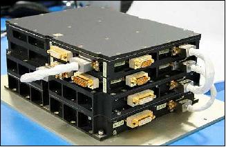
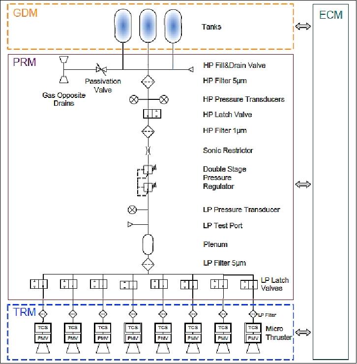
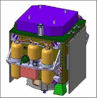
The CGPS is composed by two identical and independent subsystems called CGPSS (Cold Gas Propulsion Sub-System) which are accommodated on –Z and +Z panels (Figure 9). Each CGPSS (Figure 30) is composed of 4 modules:
• GDM (Gas Distribution Module) stores and maintains the gas at its operational range (pressure and temperatures).
• PRM (Pressure Regulation Module), provides the gas distribution to the thrusters, it contains all the equipment units necessary to ensure the pressure regulation of the CGPS.
• TRM (Thrust Regulation Module) contains 4 nominal and 4 redundant MT (Micro Thrusters).
• ECM (Electronics Control Module) contains the electronics items necessary to provide the power supply to all the CGPSS modules, control the TRM thrust, and ensure the avionic I/F with the OBC.
Each GDM is composed by 3 Arde D5048 carbon overlapped pressure vessels filled with 8.25 kg of gaseous Nitrogen stored at the maximum pressure of 345 bar.
PRM is composed of existing off-the-shelf equipment, only the pressure regulator needs to be delta qualified to withstand the maximum pressure of 345 bar.
CGPS is developed by CNES, ESA is providing the TRM and ECM devices; the CGPS design is mainly based on the GAIA MPS microthrusters developed by TAS-I.
The candidate MTs (Micro Thrusters) are those developed by TAS-I in the frame of the GAIA project (launch planned for 2013); their qualification has been achieved in 2011. The MTs operate in a close-loop configuration using a miniaturized MFS (Mass Flow Sensor) as thrust measurement and piezoelectric actuator to modify the nozzle section and modulate the gas flow.
The candidate ECM is a new MicroSCOPE development based on the existing equivalent electronic module of GAIA; the MT driver boards and DC/DC boards are the same as those of GAIA; the CPU card and the I/O card have been designed specifically for MicroSCOPE.
To improve the ECM time response, a specific new algorithm including an anti-hysteric controller, has been under study by TAS-I. This package is planned to be implemented in ECM of MicroSCOPE.
Two other technologies, developed in Europe, are under consideration for MT and its control electronic: 1) a Bradford concept controlled through a pressure sensor, and 2) the MEMS technology developed by Nanospace. Their performances (Isp, noise, thrust range, resolution, etc..) should be compliant to the MicroSCOPE main requirements; an ITT (Invitation to Tender) has been issued by ESA to select one of them.
The CGPS shall be operated on a continuous basis, because the noise generated by the pulsed thrusters is not compliant with the noise specification and would saturate the T-SAGE range.
Thrust range | 1-300 µN |
Resolution | 2 µN |
Thrust axial noise | < 3.22 µN rms in the (0.001:10) Hz bandwidth. |
Thrust linearity | < 5% |
Response time | 250 ms at 1σ) in total thrust performance range |
Auxiliary payloads on MicroSCOPE
GNSS subsystem:
The GNSS subsystem, based on two GPS antennas and a new equipment, is a low-cost software Galileo/GPS receiver under development at TES. It is a technological passenger which will be used for on ground orbit determination in addition to Doppler ranging.
IDEAS (Innovative DEorbiting Aerobrake System)
CNES is abiding by the "Space Debris Code of Conduct" rule, adopted in 2004, which recommends that after the end of operational life, the orbital life span of a LEO spacecraft should be < 25 years. 58)
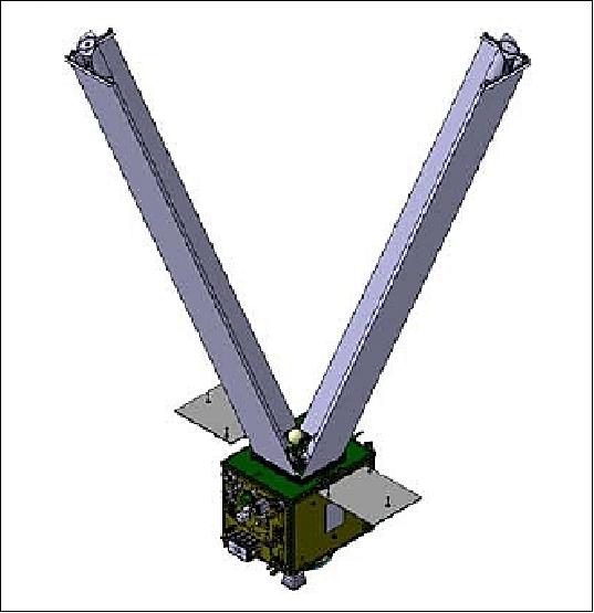
MicroSCOPE adopts a passive deorbiting subsystem based on two sails deployed at the end of the mission by two Gossamer arms. In this way the surface/mass ratio is increased and the altitude of the orbit is naturally reduced by the atmospheric drag. The inflating of the arms is ensured by gaseous Nitrogen stored at high pressure in a dedicated titanium vessel. A passive solution has been preferred to an active (solid propulsion) implementation because of its low development cost and its adaptability to the existing design of MicroSCOPE.
A drag strategy, based on deployable wings with an inflatable mast, was selected. Two 4.5 kg wings made of an aluminized Kapton membrane (100 gram/m2 density) will be deployed by a central inflatable mast - providing a total mean drag surface of 6.3 m2. The deorbit assembly has a total mass of 12 kg.
To avoid the generation of long orbital decay, the membrane is reinforced by an embedded mesh. A patented inflated mast concept of Astrium Space Transportation will be used. From the folded state, deployment is controlled by TADECS (Tetragonal Accordion Deployment Control System). The inflation system is based on cold gas technology. It should be flexible enough to be usable for applications of various sizes.
Ground Segment
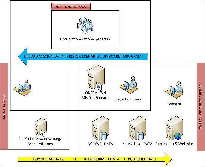
The MICROSCOPE ground segment is composed of three entities: 59) 60)
• CCC (Command Control Center) at CNES in Toulouse. The CCC in turn is composed of three elements:
- A Command Control Center (CCC). This component comprises a nominal center and a redundant center.
- TTCET (Telemetry and TeleCommand Earth Terminal 2 GHz)
- A Data Communication Network.
• DCEC ( Drag Compensation Expertise Center) at CNES which is the main part of Microscope operations. It has a double role in the expertise of the satellite functions directly participating to the scientific mission and the realization of Microscope specific operational activities: the elaboration of the programming in association with the SMC (Scientific Mission Center), the generation of the telecommands for the instrument and the SCAA, the restitution of attitude and orbit, the computing of the remaining cold gas.
• SMC ( Scientific Mission Center) located at ONERA (near Paris) which gathers the instrument telecommand preparation functions, instrument functioning optimization, processing, archiving and scientific data delivery. It is developed under Monera's responsibility in collaboration with OVA for the processing software.
The interactions between the CNES and ONERA centers are illustrated in Figure 34. The SMC, together with the DCEC, constructs the mission scenario and the on-board program, and uploads it to the CCC. Once the planned scenario is run in flight, the CCC will download the measured data to the SMC while the DCEC will compute the orbit restitution. The data is then processed by the SMC in different levels.
The first level (N0) corresponds to the operational data. The second level (N1) of data is organized by session (calibration or EP test sessions) and corresponds to the measured accelerations per sensor. The third level (N2) gives the common and differential accelerations. The N1 and N2 levels both include 3 sublevels: a) raw data, with some minor corrections from on-ground estimation of instruments parameters; b) calibrated data from in-flight estimation of instruments parameters; c) calibrated data with refined estimation (in particular by taking into account the time variations of the calibration parameters).
A group of experts and scientists, called the SWG (Science Working Group) will be in charge of data analysis processing, examining the precision of the results and approve the distribution of the data to the scientific community.
References
1) R. Chhun, D. Hudson, P. Flinoise, M. Rodrigues, P. Touboul, B. Foulon, "Equivalence principle test with microscope: Laboratory and engineering models preliminary results for evaluation of performance," Acta Astronautica ,Vol. 60, Issues 10-11, May-June 2007, pp. 873-879
2) P. Touboul, B. Foulon, L. Lafargue, G. Metris, "The MicroSCOPE Mission," Acta Astronautica Vol 50, No 7, 2002, pp. 433-443,
3) http://microscope.onera.fr/
4) J.-B. Dubois, Y. André, P. Prieur, B. Pouilloux, "Microscope, a femto-g accelerometry mission: technologies and mission overview," Proceedings of the 4S Symposium: `Small Satellite Systems and Services,' Chia Laguna Sardinia, Italy, Sept. 25-29, 2006, ESA SP-618
5) Science Contributions for MICROSCOPE, a CNES/ESA Collaborative Mission to test the Equivalence Principle, Dec. 21, 2001, URL: http://sci2.esa.int/Microscope/microscope-ao_final.pdf
6) http://www.cnes.fr/html/_455_461_2847_.php
7) P. Touboul, M. Rodrigues, G. Métris, B. Tatry, "MicroSCOPE, testing the equivalence principle in space," Compte Rendu de l'Académie des Sciences, Série 4, Tome 2, No 9, 2001, pp. 1271-1286
8) D. Hudson, P. Touboul, M. Rodrigues, "The MicroSCOPE Mission and Pre-Flight Performance Verification," 9th ICATPP Conference on Astroparticle, Particle, Space Physics, Detectors and Medical Physics Applications, Como, Italy, 17-21 Oct 17-21, 2005
9) http://smsc.cnes.fr/MICROSCOPE/index.htm
10) Vincent Josselin, Ratana Chhun, Pierre Touboul, Gille Métris, "The experiment scenario and performance of the MICROSCOPE mission," Proceedings of the 59th IAC (International Astronautical Congress), Glasgow, Scotland, UK, Sept. 29 to Oct. 3, 2008, IAC-08-A2.1.1
11) Valerio Cipolla, Jean-Bernard Dubios, Benjamin Pouilloux, Pascal Prieur, "Microscope: A Microsatellite for Equivalence Principle Measurement in Space," Proceedings of the 25th Annual AIAA/USU Conference on Small Satellites, Logan, UT, USA, Aug. 8-11, 2011, paper: SSC11-I-3
12) Agnès Levy, Émilie Hardy, Manuel Rodrigues, Bernard Foulon, Pierre Touboul, Gilles Métris, "The Microscope space mission: from flight hardware to in-orbit calibration," Proceedings of the 63rd IAC (International Astronautical Congress), Naples, Italy, Oct. 1-5, 2012, paper: IAC-12-A2.1.1
13) Agnès Levy, Émilie Hardy, Manuel Rodrigues, Bernard Foulon, Pierre Touboul, Gilles Métris, "The in-orbit calibration plan for the accelerometer of the MicroSCOPE space mission," Proceedings of the 64th International Astronautical Congress (IAC 2013), Beijing, China, Sept. 23-27, 2013, paper: IAC-13-A2.1.5
14) Vincent Josselin, Pierre Touboul, Manuel Rodrigues, Françoise Liorzou, "MICROSCOPE On-ground and In-orbit Calibration," Space Science Review, Vol. 151, 2010, pp: 25-38, URL: http://microscope3.sciencesconf.org/conference/microscope3/pages/2010
_Josselin_SSR_MICROSCOPE_On_ground_and_In_orbit_Calibration_.pdf
15) Zentrum für angewandte Raumfahrttechnologie und Mikrogravitation (Center of Applied Space Technology and Microgravity - since 1985), an institute of the University of Bremen, Germany
16) Joel Berge, Pierre Touboul, Manuel Rodrigues and the MICROSCOPE Team, "Status of MICROSCOPE, a mission to test the Equivalence Principle in space," Jan. 2015, URL: http://arxiv.org/pdf/1501.01644.pdf
17) P. W. Bousquet, B. Pouilloux, C. Serieys, E. Bellouard, C. Puillet, J.-B. Dubois, "MicroSCOPE - Extreme Stability Requirements for Femto-g Measurements," 58th IAC (International Astronautical Congress), International Space Expo, Hyderabad, India, Sept. 24-28, 2007, IAC-07-C2.7.03
18) http://smsc.cnes.fr/MICROSCOPE/GP_satellite.htm
19) Françoise Liorzou, Manuel Rodrigues, Damien Boulanger, Vincent Lebat, Bernard Foulon, Pierre Touboul, "T-SAGE, the MICROSCOPE Mission Payload ready to test the Equivalence Principle in space," Proceedings of the 66th International Astronautical Congress (IAC 2015), Jerusalem, Israel, Oct.12-16, 2015, paper: IAC-15.A2.1.1
20) Manuel Rodrigues, Damien Boulanger, Phuong-Anh Huynh, Pierre Touboul, "Status of the Flight Payload of the Microscope Space Mission," Proceedings of the 65th International Astronautical Congress (IAC 2014), Toronto, Canada, Sept. 29-Oct. 3, 2014, paper: IAC-14.A2.1.5
21) Hans Selig, Andreas Gierse, Pierre Touboul, Françoise Liorzou, Manuel Rodrigues, "Free fall Payload Tests for the MICROSCOPE Space Mission," Proceedings of the 65th International Astronautical Congress (IAC 2014), Toronto, Canada, Sept. 29-Oct. 3, 2014, paper: IAC-14-A2.1.6
22) Valerio Cipolla, Jean-Bernard Dubios, Benjamin Pouilloux, Pascal Prieur, "Microscope: A Microsatellite for Equivalence Principle Measurement in Space," Proceedings of the 25th Annual AIAA/USU Conference on Small Satellites, Logan, UT, USA, Aug. 8-11, 2011, paper: SSC11-I-3
23) "Sentinel-1B lifts off," ESA, April 25, 2016, URL: http://www.esa.int/spaceinimages/Images/2016/04/Sentinel-1B_lifts_off
24) "Sentinel-1B – Second eye of the Earth guardian in orbit," DLR, April 26, 2016, URL: http://www.dlr.de/dlr/en/desktopdefault.aspx/tabid-10081/
151_read-17549/year-all/#/gallery/22793
25) "Space MicroSCOPE to test universality of freefall," ESA, April 26, 2016, URL: http://www.esa.int/Our_Activities/Space_Science/
Space_Microscope_to_test_universality_of_freefall
26) "Soyuz Flight VS14 with Sentinel-1B, Microscope and Fly Your Satellite!," Arianespace, April 25, 2016, URL: http://www.arianespace.com/mission/ariane-flight-vs14/
27) "Approaching launch: student CubeSats integrated on their orbital deployer," ESA, March 17, 2016, URL: http://www.esa.int/Education/CubeSats_-_Fly_Your_Satellite/Approaching_launch
_Student_CubeSats_integrated_in_their_orbital_deployer
28) "End of mission for Microscope - CNES's satellite bows out with successful and innovative de-orbiting," CNES, 18 October 2018, URL: https://presse.cnes.fr/en/end-mission-microscope-cness-satellite-
bows-out-successful-and-innovative-de-orbiting
29) Joël Bergé, Ratana Chhun, Emilie Hardy, Manuel Rodrigues, Pierre Touboul, Gilles Metros, Alain J. M. Robert, "Current results of the MICROSCOPE space mission: a test of equivalence principle," Proceedings of the 69th IAC (International Astronautical Congress) Bremen, Germany, 1-5 October 2018, paper: IAC-18.A2.1.1, URL: https://iafastro.directory/iac/proceedings/IAC-18/IAC
-18/A2/1/manuscripts/IAC-18,A2,1,1,x44308.pdf
30) Pierre Touboul, Gilles Métris, Manuel Rodrigues, Yves André, Quentin Baghi, Joël Bergé, Damien Boulanger, Stefanie Bremer, Patrice Carle, Ratana Chhun, Bruno Christophe, Valerio Cipolla, Thibault Damour, Pascale Danto, Hansjoerg Dittus, Pierre Fayet, Bernard Foulon, Claude Gageant, Pierre-Yves Guidotti, Daniel Hagedorn, Emilie Hardy, Phuong-Anh Huynh, Henri Inchauspe, Patrick Kayser, Stéphanie Lala, Claus Lämmerzah, Vincent Lebat, Pierre Leseur, Françoise Liorzou, Meike List, Frank Löffler, Isabelle Panet, Benjamin Pouilloux, Pascal Prieur, Alexandre Rebray, Serge Reynaud, Benny Rievers, Alain Robert, Hanns Selig, Laura Serron, Timothy Sumner, Nicolas Tanguy, Pieter Visser, "MICROSCOPE Mission: First Results of a Space Test of the Equivalence Principle," Physical Review Letters, Vol. 119, Issue 23 — 8, December 2017, DOI:https://doi.org/10.1103/PhysRevLett.119.231101
31) T. A. Wagner, S. Schlamminger, J. H. Gundlach, E. G. Adelberger, "Torsion-balance tests of the weak equivalence principle," Classical Quantum Gravity, Vol. 29:184002, 15 Aug. 2012, DOI: 10.1088/0264-9381/29/18/184002, URL: https://arxiv.org/pdf/1207.2442.pdf
32) Clifford M. Will, "The Confrontation between General Relativity and Experiment," Living Reviews in Relativity, Vol. 17, 28 March 2014, doi:10.12942/lrr-2014-4, URL: https://link.springer.com/content/pdf/10.12942%2Flrr-2014-4.pdf
33) B. P. Abbott, R. Abbott, T. D. Abbott, M. R. Abernathy, F. Acernese, K. Ackley, C. Adams, T. Adams, P. Addesso, et al., "Observation of Gravitational Waves from a Binary Black Hole Merger," Physical Review Letters, Vol. 116, 061102, 12 Feb. 2016, DOI: 10.1103/PhysRevLett.116.061102, URL: https://physics.aps.org/featured-article-pdf/10.1103/PhysRevLett.116.061102
34) T. Damour, A. M. Polyakov, "The string dilation and a least coupling principle," Nuclear Physics B, Science Direct, Volume 423, Issues 2–3, 25 July 1994, Pages 532-55, https://doi.org/10.1016/0550-3213(94)90143-0
35) Thibault Damour, Federico Piazza, Gabriele Veneziano, "Runaway dilaton and equivalence principle violations," Physical Review Letters, Vol. 89, 2002, DOI: 10.1103/PhysRevLett.89.081601, URL: https://arxiv.org/pdf/gr-qc/0204094.pdf
36) Justin Khoury, Amanda Weltman, "Chameleon Fields: Awaiting Surprises for Tests of Gravity in Space," Physical Review Letters, Volume 93, 171104,2004, DOI: 10.1103/PhysRevLett.93.171104, URL: https://arxiv.org/pdf/astro-ph/0309300.pdf
37) Pierre Fayet, "Extra U(1)'s and new forces," Science Direct, Nuclear Physics B, Volume 347, Issue 3, 31 December 1990, Pages 743-768, https://doi.org/10.1016/0550-3213(90)90381-M
38) Pierre Fayet, "The light U boson as the mediator of a new force, coupled to a combination of Q, B, L and dark matter," High Energy Physics - Phenomenology, DOI: 10.1140/epjc/s10052-016-4568-9, European Physical Journal C, Vol. 77:53, 2017, URL: https://arxiv.org/pdf/1611.05357.pdf
39) Valerio Cipolla, Yves Andre, Pierre-Yves Guidotti, Alain Robert, Pascal Prieur, "Microscope : First satellite dedicated to measure the principle of equivalence in space," Proceedings of the 68th IAC (International Astronautical Congress), Adelaide, Australia, 25-29 Sept. 2017, paper: IAC-17-A2.1.1
40) "Microscope satellite first results looking very promising," CNES Press Release, Dec. 7, 2016, URL: https://presse.cnes.fr/en/microscope-satellite-first-results-looking-very-promising
41) "CNES ONERA cooperation first ultra-precise measurements from Microscope," CNES Press Release, Sept. 27, 2016, URL: https://presse.cnes.fr/en/cnes-onera-cooperation-
first-ultra-precise-measurements-microscope
42) Manuel Rodrigues, Pierre Touboul, Ratana Chhun, Françoise Liorzou, Gilles Metris, "MICROSCOPE a microsatellite for a major cornerstone in fundamental physics, from qualification to launch," Proceedings of the 4S (Small Satellites, System & Services) Symposium, Valletta, Malta, May 30-June 3, 2016, URL: http://congrexprojects.com/docs/default-source
/16a02_docs/4s2016_final_proceedings.zip?sfvrsn=2
43) "Student satellites fly freely on their orbit in space," ESA, April 26, 2016, URL: http://www.esa.int/Education/CubeSats_-_Fly_Your_Satellite/Student_
satellites_fly_freely_on_their_orbit_in_space
44) "Soyuz demonstrates Arianespace mission flexibility," Space Daily, April 26, 2016, URL: http://www.spacedaily.com/reports/Soyuz_demonstrates_
Arianespace_mission_flexibility_999.html
45) D. Hudson, R. Chhun, P. Touboul, "Development of a Differential Accelerometer to Test the Equivalence Principle in the Microscope Mission;" Proceedings of IAC 2004, Vancouver, Canada, Oct. 4-8, 2004, IAC-04-J.1.02
46) http://microscope.onera.fr/payload.html
47) D. Hudson, R. Chhun, P. Touboul, "Development of a Differential Accelerometer to Test the Equivalence Principle in the Microscope Mission, Acta Astronautica, Vol. 57, April 2005, pp.341-347
48) R. Chhun, D. Hudson, P. Flinoise, M. Rodrigues, P. Touboul, B. Foulon, "Equivalence Principle Test with Microscope: Laboratory and Engineering Models Preliminary Results for Evaluation of Performance," Proceedings of IAC 2005, Fukuoda, Japan, Oct. 17-21, 2005, IAC-05-A2.1
49) D. Hudson, M. Rodrigues, R. Chhun, P. Touboul, "The Microscope Instrument Realization Challenge and Performance Assessment," Proceedings of the 57th IAC/IAF/IAA (International Astronautical Congress), Valencia, Spain, Oct. 2-6, 2006, IAC-06-A2.1.1
50) E. Guiu, M. Rodrigues, P. Touboul, "Microscope modelisation and results of the calibration phase," Proceedings of the 57th IAC/IAF/IAA (International Astronautical Congress), Valencia, Spain, Oct. 2-6, 2006, IAC-06-A2.1.02
51) J. Mester, "Testing the Equivalence Principle in Space," IHP 2006, URL: http://luth2.obspm.fr/IHP06/lectures/mester-vinet/IHP-5EP-Space.pdf
52) M. Rodrigues, F. Liorzou, V. Lebat, P. Touboul, B. Foulon, R. Chhun, "T-SAGE : The challenging payload of the Microscope micro satellite," Proceedings of the 59th IAC (International Astronautical Congress), Glasgow, Scotland, UK, Sept. 29 to Oct. 3, 2008, IAC-08.B4.2.10
53) Manuel Rodrigues, "Development status of the MICROSCOPE payload," Proceedings of the GPhyS (Gravitation and Fundamental Physics in Space) Kick-Off Colloquium, Les Houches, France, Oct. 20-22, 2009, URL: http://gphys.obspm.fr/LesHouches2009/GPhyS1009/
oct20/les-houches-m.rodrigues.pdf
54) Manuel Rodrigues, Guillaume Bodoville, Ratana Chhun, Pierre Touboul, Lebat Vincent, "High accurate geometrical machining and metrology for the MICROSCOPE instrument," Proceedings of the 61st IAC (International Astronautical Congress), Prague, Czech Republic, Sept. 27-Oct. 1, 2010, IAC-10.A2.1.10
55) Manuel Rodrigues, Pierre Touboul, Ratana Chhun, "MICROSCOPE, a drag-free controlled test of the equivalence principle in space," Proceedings of the 4S (Small Satellites Systems and Services) Symposium, Portoroz, Slovenia, June 4-8, 2012
56) G. Pradels, P. Touboul, "In orbit calibration approach of the MICROSCOPE experiment for the test of the Equivalence Principe," Classical Quantum Gravity, No 20, 2003, pp. 2677-2688
57) The information was provided by Valerio Cipolla of CNES, France.
58) P. W. Bousquet, C. Dupuy, T. Bonnefond, "De-orbiting Microscope spacecraft by drag enhancement," Proceedings of the 57th IAC/IAF/IAA (International Astronautical Congress), Valencia, Spain, Oct. 2-6, 2006, IAC-06-B6.4.5
59) http://missions-scientifiques.cnes.fr/MICROSCOPE/GP_segment_sol.htm
60) Quentin Baghi, Bruno Christophe, Gilles Métris, Pierre Touboul, Manuel Rodrigues, "The data analysis challenge of the MICROSCOPE space mission," Proceedings of the 66th International Astronautical Congress (IAC 2015), Jerusalem, Israel, Oct.12-16, 2015, paper: IAC-15-A2.1.2
The information compiled and edited in this article was provided by Herbert J. Kramer from his documentation of: "Observation of the Earth and Its Environment: Survey of Missions and Sensors" (Springer Verlag) as well as many other sources after the publication of the 4th edition in 2002. - Comments and corrections to this article are always welcome for further updates (eoportal@symbios.space).
Spacecraft Launch Mission Status Sensor Complement Ground Segment References Back to Top