Meteor-3M-1
EO
Atmosphere
Ocean
Cloud type, amount and cloud top temperature
Quick facts
Overview
| Mission type | EO |
| Agency | ROSKOSMOS, ROSHYDROMET |
| Mission status | Mission complete |
| Launch date | 01 Dec 2001 |
| End of life date | 01 Apr 2008 |
| Measurement domain | Atmosphere, Ocean, Land, Snow & Ice |
| Measurement category | Cloud type, amount and cloud top temperature, Liquid water and precipitation rate, Atmospheric Temperature Fields, Cloud particle properties and profile, Aerosols, Multi-purpose imagery (ocean), Radiation budget, Multi-purpose imagery (land), Surface temperature (land), Vegetation, Albedo and reflectance, Surface temperature (ocean), Atmospheric Humidity Fields, Ozone, Trace gases (excluding ozone), Sea ice cover, edge and thickness, Snow cover, edge and depth, Ocean surface winds, Atmospheric Winds |
| Measurement detailed | Cloud top height, Ocean imagery and water leaving spectral radiance, Aerosol absorption optical depth (column/profile), Cloud cover, Precipitation intensity at the surface (liquid or solid), Aerosol optical depth (column/profile), Cloud type, Cloud imagery, Aerosol Extinction / Backscatter (column/profile), Cloud liquid water (column/profile), Land surface imagery, Upward long-wave irradiance at TOA, Aerosol effective radius (column/profile), Vegetation type, Fire fractional cover, Earth surface albedo, Short-wave Earth surface bi-directional reflectance, Land cover, Atmospheric specific humidity (column/profile), O3 Mole Fraction, Atmospheric temperature (column/profile), Land surface temperature, Sea surface temperature, CH4 Mole Fraction, NO2 Mole Fraction, Sea-ice cover, Snow cover, Wind speed over sea surface (horizontal), Normalized Differential Vegetation Index (NDVI), BrO (column/profile), Sea-ice thickness, Iceberg fractional cover, Sea-ice type, Oil spill cover, Height of tropopause |
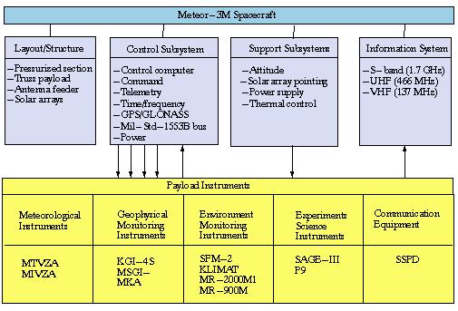
| Instruments | BRK, DCS, MR-2000M1, Klimat, SFM-2, MIVZA, KMSS, MSU-E, SAR, MSU-SM, IKFS-2, MSTE-5E, KGI-4C, SAGE III, MTVZA-GY, MSGI-5EI, MSU-MR |
| Instrument type | Imaging multi-spectral radiometers (vis/IR), High resolution optical imagers, Earth radiation budget radiometers, Other, Atmospheric chemistry, Imaging multi-spectral radiometers (passive microwave), Data collection, Imaging microwave radars, Atmospheric temperature and humidity sounders |
| CEOS EO Handbook | See Meteor-3M-1 summary |
Meteor-3M-1
The Meteor-3M spacecraft series represents a modernization of Russia's national meteorological satellite system sponsored by Roskosmos, Moscow. The overall objective are environmental monitoring in the following fields:
• Monitoring of ocean and land surfaces
• Meteorological observations: Distribution of cloud data and vertical ozone profiles, monitoring of global atmospheric parameters such as temperature and water vapor profiles and to obtain sea surface wind profiles and SST
• Measurement of vertical profiles of aerosol, ozone and other constituents in the atmosphere (SAGE-III)
• Measurement space environment parameters (space weather) such as: particle fluxes and radiation density fluxes.
The US instrument SAGE-III is flown on the Meteor-3M-1 mission (joint mission of Rosaviakosmos and NASA). A corresponding cooperative agreement was approved by the Gore-Chernomyrdin Commission on Dec. 16. 1994. Plans for Meteor-3M are to combine the meteorological observations of the Meteor-3 series with the Earth-surface observations of the Resurs series, starting with Meteor-3M-2 (also referred to as Meteor-3M-1) with a planned launch in 2007 (operational capability for meteorology applications). 1) 2) 3) 4)
Spacecraft
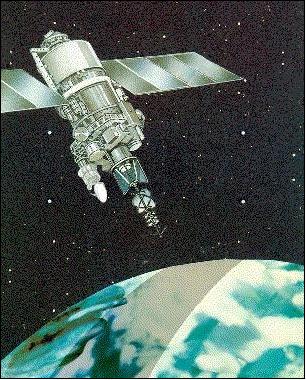
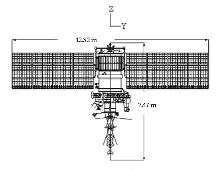
The Meteor-3M-1 spacecraft was designed and built by NIIEM (Scientific Research Institute for Electromechanics) in Istra, Russia. The spacecraft structure consists of: a) hermetic container with instrument rack, b) instrument platform, and c) solar arrays. Most electronics and some service system modules are contained in the hermetic container. Most payload instruments and some service modules are mounted to the external thermally stabilized platform. Significant changes have been introduced including the modification of attitude system, installation of new radio transmission system and modification of the information devices and measurement instruments.
The spacecraft is three-axis stabilized. The S/C pointing accuracy 0.1º, the angular drift rate is 0.0005º/s. A navigation subsystem (GPS/GLONASS receiver) provides orbit determination and timing services. Solar power of 2 kW (BOL) is provided by two deployed panels which are continuously sun pointed for optimum power generation (solar panel area of 23 m2, solar array span of 14 m). The S/C mass is about 2500 kg (payload mass of ~900 kg), the design life is three years.
Launch
A launch of Meteor-3M-1 took place on Dec. 10, 2001 on a Zenit-2 launch vehicle from the Baikonur Cosmodrome, Kazakhstan (launch provider: NPO Yuzhnoye).
Secondary payloads on the flight are the Badr-B satellite of Pakistan, Maroc-Tubsat of Morocco, the Compass spacecraft of IZMIRAN, Moscow, and REFLECTOR (Retroreflector Ensemble For Laser Experiments Calibration Testing & Optical Research), a US/Russian nanosatellite, funded by AFRL and developed by ISDE (Institute of Space Device Engineering), Moscow. The objective of the passive REFLECTOR spacecraft is to support SLR (Satellite Laser Ranging) experiments. 5)
Orbit: Sun-synchronous near-circular polar orbit, altitude = 1012 km, eccentricity = 0.0024, inclination = 99.63º, local time of ascending node is 9:15 AM, period = 105.33 min, path offset/revolution = 26.334º, revisit time = 3 days (41 revolutions).
RF communications: An onboard information system (OBIS) is being used for recording of instrument data streams up to 150 kbit/s from a single instrument. The solid-state recorder has a capacity of 100 Gbit. OBIS provides time compression of collected data streams with the following output options (RF data downlinks). OBIS has a mass of 20 kg and a power consumption of 32 W.
• S-band (N1 digital data streams, 1.67-1.71 GHz broadcast to HRPT-compatible stations at a data rate of 665.4 kbit/s, NOAA-POES series compatible)
• S-band (N2 digital data stream, 1.67-1.71 GHz broadcast to a ground network of AIRS (Autonomous Information Reception Station) at a data rate of 66.54 kbit/s)
• VHF-band (analog data stream, 137.3-137.85 MHz broadcast compatible with APT standard)
• X-band (8.320, 8.064 or 8.192 GHz, digital recorder dump rate of 61.44 Mbit/s and 15.36 Mbit/s to ground stations).
The S/C monitoring and control functions (TT&C) are being performed by the Roskosmos Mission Control Center in Korolev (Moscow Region), Russia. The payload data are being received, processed and archived by NPO Planeta, the main center of Roshydromet. The SAGE-III data capture and processing is being performed at NASA/LaRC via a WFF (Wallops Flight Facility) ground station.
Mission Status
The Meteor-3M spacecraft stopped functioning on March 6, 2006 due to a breakdown of its power supply system resulting in a loss of communications with the spacecraft. - With a launch on Dec. 10, 2001, the spacecraft (with a design life of 3 years) provided over 4 years of successful operations.
Sensor Complement
The Meteor-3M-1 sensor complement consists of the following instruments: MR-2000-M1; KLIMAT; MIVZA; MTVZA; MSU-E; SAGE-III; SFM-2; KGI-4C, and MSGI-5EI. 6) 7) 8)
[Note: The Meteor-3M-2 sensor complement consists of the following instruments: MTVZA, MSU-MR (2 instruments), MSU-SR (2 instruments), IKFS-2, MSGI-MKA, KGS-4S, a DCS (Data Collection System), RRA (RetroReflector Array), and SAGE-III of NASA/LaRC.]
Instrument | Application | Spectral band | Swath width | Resolution |
MR-2000M1 | Cloud cover mapping | 0.5 - 0.8 µm | 3100 km | 0.7 km x 1.4 km |
KLIMAT | Global and regional cloud cover mapping, SST | 10.5 - 12.5 µm | 3100 km | 3 km x 3 km |
MIVZA | Total humidity of the atmosphere | 20.0-94.0 GHz | 1500 km | 80 km to 40 km |
MTVZA | Atmospheric temperature and humidity profiles | 18.7-183.3 GHz | 2200 km | 12-75 km |
MSU-E | Multispectral images of high spatial resolution | 0.5 - 0.6 µm | 76 km within a FOR of 430 km | 38 m |
SAGE-III | Profiles of aerosols, ozone, NO2, and other atmospheric constituents | 0.29 - 1.55 µm |
| 1-2 km (vertical) |
SFM-2 | Vertical distribution of ozone | UV band |
|
|
KGI-4C | Space environment | 0.1 keV-90 MeV |
|
|
RRA | SLR (Satellite Laser Ranging) |
|
|
|
MR-2000M1 (TV Camera System-2000-M1)
Objective: Observation of daytime Earth cloud cover in the visible spectrum (0.5 - 0.8 µm) at a local solar angle not less than 5º. Spatial resolution of 0.7-1.4 km. The instrument has been flown on the following missions: Meteor-3-1 (1985), Meteor-3-3, Meteor-3-4, Meteor-3-5, Meteor-3-6, and Meteor-3-7. The MR-2000M1 camera provides storage and direct transmission operation.
Klimat (Infrared Radiometer)
The instrument was originally flown on the Meteor-3 series, operational since 1988 (Meteor-3-3 to Meteor-3-7). Klimat is an electromechanical device with a scan angle of ± 48º, providing a total swath width of 3100 km. IFOV=0.7 x 1.4 mrad; surface temperature range = 223-313 K; temperature difference at 300 K, background = 0.2 K. Measurement spectrum: 10.5 to 12.5 µm. Instrument mass = 75 kg. Detectors: CdHgTe cooled to 80 K. Output products: Global photomosaics of northern and southern hemispheres, tropical zone, individual images; digital SST and top-of-cloud height charts, tropical cyclone coordinates, cloud amount data on regular grid over the globe.
MIVZA (Microwave Humidity Sounder) of Roshydromet
The objective is to provide an estimate on the total humidity of the atmosphere (water vapor). MIVZA is a 5-channel scanning radiometer within the 20-90 GHz range.
MSU-E (High-Resolution Multispectral Pushbroom Imager)
The instrument provides three spectral bands (0.5 - 0.6 µm, 0.6 - 0.7 µm, 0.8 - 0.9 µm), the spatial resolution is 38 m with a swath width of 76 km. The instrument features a cross-track pointing capability thus providing a FOR (Field of Regard) of 430 km. Data quantization of 8 bit. - MSU-E was also flown on the Resurs-O1 series (1985-2000) and on the PRIRODA module of the MIR Station.
From a historical point of view: Spaceborne CCD pushbroom detector technology was globally introduced with MSU-E, first flown on the Meteor-Priroda-5 (launch June 18, 1980) spacecraft of the former Soviet Union. 9) MSU-E was built at ISDE (Russian Institute of Space Device Engineering) in Moscow; it featured a CCD line array of 1024 pixels, three parallel line arrays, each of 1024 elements, and provided pushbroom imagery in three spectral bands (visible range). MSU-E provided a nadir view with a FOV of 2.5º. A radiation cooler provided a detector temperature in the range of -30 to -50ºC. Instrument mass of 17 kg. No in-flight calibration was performed.
MTVZA (Microwave Imaging/Sounding Radiometer)
MTVZA was designed and developed at the Space Observations Center, Moscow, under contract to Roskosmos. MTVZA is a passive 26-channel microwave radiometer (similar to NOAA's AMSU-A and -B radiometers).
The objective of the MTVZA instrument is to monitor ocean and land surfaces as well as global atmospheric parameters such as temperature and water vapor profiles and to obtain sea surface wind profiles. MTVZA is a conical scanning instrument with a common field of view for imaging and sounding channels (simultaneous multispectral and polarization measurements), due to the single antenna design. The operating frequencies are located in the transparent atmospheric windows at 19, 33, 36.5, 42, 48, and 91.65 GHz, as well as in the oxygen absorption lines at 52-57 GHz and water vapor at 22.235 and 183.31 GHz. In addition, MTVZA includes some complementary (non-typical) frequencies used for oceanographic research. 10) 11) 12)
Observation geometry: MTVZA is a conical-scanning radiometer rotating continuously about an axis parallel to the local spacecraft vertical with a period of 2.5 s during which the subsatellite point, moving at 6.32 km/s, travels 15.8 km. The view direction of the instrument is backwards (anti-velocity direction) with a viewing angle of 53.5º and an incidence angle of 69º (with respect the the surface). The sampling resolution is 17.8 km x 15.8 km in the cross-track and along-track direction respectively for channels of 91.6 GHz (Table 4). The scan direction is from the left to the right when looking in the aft direction of the spacecraft, with the active scene measurements in the range from -60º to +27º about the aft direction, resulting in a swath width of 2200 km.
Observation region | Parameter | Range of measurements | Error |
Ocean | SST |
| ±1.0 K |
Atmosphere | Temperature profile | up to 45 km | ±1.5 K |
Land | Thickness of dry snow | up to 1.5 m | ±0.2 m |
Channel No | Center Frequency (GHz) | No of Passbands | Bandwidth (MHz) | Approx. Peak Sensitivity Altitude (km) | Polarization |
1 | 18.7 | 1 | 800 | - | V |
2 | 18.7 | 1 | 800 | - | H |
3 | 22.235 | 1 | 1600 | - | V |
4 | 33.0 | 1 | 2000 | - | V |
5 | 33.0 | 1 | 2000 | - | H |
6 | 36.5 | 1 | 2000 | - | V |
7 | 36.5 | 1 | 2000 | - | H |
8 | 42.0 | 1 | 2000 | - | V |
9 | 42.0 | 1 | 2000 | - | H |
10 | 48.0 | 1 | 2000 | - | V |
11 | 48.0 | 1 | 2000 | - | H |
12 | 52.80 | 2 | 400 | 2 | V |
13 | 53.30 | 2 | 400 | 4 | V |
14 | 53.80 | 2 | 400 | 6 | V |
15 | 54.64 | 2 | 400 | 10 | V |
16 | 55.63 | 2 | 400 | 14 | V |
17 | 91.65 | 2 | 3000 | Surface | V |
18 | 91.65 | 2 | 3000 | Surface | H |
19 | 183.31±7.0 | 2 | 1500 | 1.5 | V |
20 | 183.31±3.0 | 2 | 1000 | 2.9 | V |
21 | 183.31±1.0 | 2 | 500 | 5.3 | V |
22 | 57.290344±0.3222±0.1 | 4 | 50 | 20 | H |
23 | 57.290344±0.3222±0.05 | 4 | 20 | 25 | H |
24 | 57.290344±0.3222±0.025 | 4 | 10 | 29 | H |
25 | 57.290344±0.3222±0.01 | 4 | 5 | 35 | H |
26 | 57.290344±0.3222±0.005 | 4 | 3 | 42 | H |
Note: Channels 22-26 are only available in the next version of the MTVZA instrument to be flown on Meteor-3M-2
All instrument channels are switched to single feed-horn antenna. MTVZA employs a total-power radiometer design providing a better sensitivity (factor 2) over a conventional Dicke-switched system. The channels in the 19-48 GHz domain are direct amplification radiometers, while the channels in the 52-57, 91 and 183 GHz range are realized as as superheterodyne receivers using balanced mixers. The performance parameters are given in Tables 3 and 4.
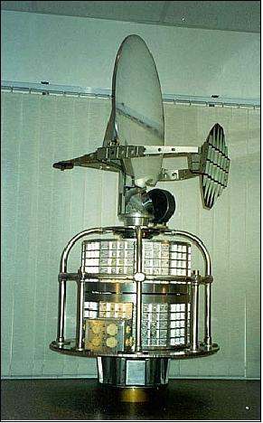
The antenna system of MTVZA consists of an offset parabolic reflector of dimensions 50 cm x 65 cm, illuminated by a broadband, eleven-port feed-horn antenna through the flat mirror. The configuration of the two mirror antenna system is due to the instrument deployment mechanism in the down part of spacecraft. The flat mirror and feed-horn antenna are mounted on a drum for the purpose to provide an invariant viewing and polarization geometry for the reflector scan. The drum contains the various system components like radiometers, digital data subsystem, power and the signal transfer assembly, which rotates continuously about an axis parallel to the local spacecraft vertical. The power, commands, all data, timing and telemetry signals pass through slip ring connectors to the rotating assembly.
Hot and cold reference absorbers are used for calibration. They are mounted on the non-rotating part of instrument and are positioned such that they pass between the feed-horn and the flat mirror, occulting the feed-horn once each scan. The temperature difference between hot and cold target is 50-60 K. The S/C test results for the hot and cold targets are in a good agreement with those obtained during ground thermal/vacuum testing.
Frequency (GHz) | 18.7 | 22.2 | 33.0 | 36.5 | 42.0 | 48.0 | 52-57 | 91.6 | 183 |
IFOV (km x km) | 75x136 | 68x124 | 45x82 | 41x75 | 36x65 | 32x58 | 30x55 | 18x33 | 12x22 |
Image pixels (km x km) | 35.6 x 31.6 | 71.2 x 63.2 | 17.8 x 15.8 | 71.2 x 63.2 | |||||
Sensitivity (K/pixel) | 0.25 | 0.25 | 0.35 | 0.38 | 0.45 | 0.45 | 0.3 | 0.5 | 0.4 |
Calibration accuracy, K | 0.5 | 0.5 | 0.6 | 0.6 | 0.7 | 0.7 | 1.0 | 1.0 | 1.1 |
Antenna beam efficiency | 93.7% | 93.4 | 93.5 | 93.5 | 92.8 | 93.9 | 94.2 | 95 | 95 |
Cross polarization isolation, dB | -24 | -24 | -25 | -24 | -20 | -23 | -25 | -24 | -25 |
Number of channels | 2 | 1 | 2 | 2 | 2 | 2 | 5 | 2 | 3 |
Polarization | V, H | V | V, H | V, H | V, H | V, H | V | V, H | V |
Spatial resolution (km) | 75 | 68 | 45 | 41 | 36 | 32 | 30 | 18 | 12 |
Conical scanning period | 2500.0 ±0.8 ms | ||||||||
Viewing angle | 53.5º | ||||||||
Incident angle | 69º | ||||||||
Swath width | 2200 km | ||||||||
Instrument mass, power | 107 kg, 110 W | ||||||||
Data rate, | 10 kbit/s | ||||||||
Geophysical Monitoring System Complex
The Geophysical Monitoring System Complex consists of two instruments: 1) MSGI-MKA (Spectrometer for Geoactive Measurements), and 2) KGI-4C (Radiation Monitoring System). - The MSGI-MKA instrument, also referred to as MSGI-5EI, features four channels for the measurement of the following parameters: 14)
• Electron fluxes in the energy range of 0.1-15 keV (high-sensitivity channel)
• Ion (proton) fluxes in the energy range of 0.1-15 keV (high-sensitivity channel)
• Electron fluxes in the energy range of 0.1-15 keV (low-sensitivity channel)
• Monitoring of integral electron fluxes with a threshold energy of 40 keV
The FOV (Field of View) is 10º x 10º for each channel (3) and 20º x 20º for the integral electron flux. The instrument has a mass of 5 kg and a power consumption of 6.8 W.
KGI-4C (Radiation Monitoring System)
The objective is to monitor flux densities within the following threshold energy ranges:
• Total proton flux threshold energy of: 5, 15, 25, 30, and 40 MeV
• Total electron flux threshold energy of: 0.17, 0.7, 1.7, 2.0 and 3.2 MeV
• Proton fluxes with threshold energies of: 25 and 90 MeV
The KGI-4C instrument has a mass of 12 kg and a power consumption of 6.8 W (max).
RRA (RetroReflector Array)
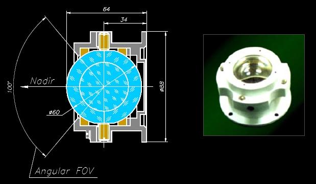
RRA is also referred to as SRR (Spherical RetroReflector), an experimental device developed by IPIE (Institute for Precision Instrument Engineering) of Moscow. The RRA is a glass ball 60 mm in diameter, fastened in a holder providing observation from Earth at elevations more than 30º (the retroreflector field of view is centered in the nadir direction). The spherical retroreflector with its holder is fixed to the METEOR-3M spacecraft. The expected return signal strength level is between LAGEOS and ETALON. A secondary mission objective is the flight testing of RRA for precise laser ranging. SLR tracking is being used for precise orbit determination and retroreflector research. SLR mission support began on 1 May 2002. 15) 16) 17)
The new type of the experimental spherical retroreflector is a ball lens made of several (at least two) layers of glass having different refraction index values.
SFM-2 (Spectrophotometer-2)
The objective is to provide an estimate of the vertical ozone distribution. Measurements are obtained using the absorption method in 4 channels in frequency band 0.25-0.6 µm. This permits the derivation of the ozone profile from approximately 5 km up to 80 km in altitude.
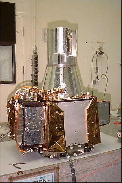
SAGE III (Stratospheric Aerosol and Gas Experiment III)
SAGE-III PI: M. P. McCormick, Hampton University, Hampton, VA (formerly NASA/LaRC). The instrument was built at Ball Aerospace of Boulder, CO, as prime contractor. SAGE-III was selected to fly on Meteor-3M and on ISS (International Space Station) in 2005. SAGE III is an Earth limb-scanning grating spectrometer to measure vertical profiles of aerosol, ozone and other constituents in the atmosphere. The SAGE-III instrument is part of the NASA EOS mission in characterizing the Earth system. 18) 19) 20) 21)
Background and heritage: SAM [SAM (Stratospheric Aerosol Measurement) was flown on ASTP (Apollo-Soyuz Test Project), July 15-24, 1975, to perform the first successful solar occultation measurement of stratospheric aerosol], SAM II (launch Oct. 24, 1978 on Nimbus-7), SAGE I, SAGE II). Both SAM and SAM-II were single spectral instruments measuring the aerosol extinction near the 1000 nm wavelength region. Multiple spectral measurements began with SAGE-I, with a launch on the AEM-2 (Application Explorer Mission-2) satellite, Feb. 18, 1979. SAGE-II is an advanced version of SAGE-I with 7 channels at 385, 448, 453, 525, 600, 940, and at 1020 nm. SAGE-II was flown on ERBS with a launch on Oct. 5, 1984 (as of 2004 SAGE-II is still operational on ERBS). The measurements of SAM-II, SAGE-I and SAGE-II have provided long-term observations of aerosol and ozone for over 20 years. 22)
The SAGE-III instrument has the following science objectives: 23) 24) 25) 26) 27)
• Retrieve global profiles (with 1 to 2 km vertical resolution) of atmospheric aerosols, ozone, water vapor, NO2, NO3, OClO, temperature and pressure in the mesosphere, stratosphere and troposphere
• Investigate the spatial and temporal variability of the measured species in order to determine their role in climatological processes, biogeochemical cycles, the hydrologic cycle, and atmospheric chemistry
• Characterize tropospheric and stratospheric aerosols and upper tropospheric and stratospheric clouds, and investigate their effects on the Earth's environment, including radiative, microphysical, and chemical interactions
• Extend the SAM II, SAGE I and SAGE II self-calibrating solar occultation data sets (begun in 1978), enabling the detection of long-term trends
• Provide atmospheric data essential for the calibration and interpretation/correction of other satellite sensors, including EOS- and ground-based sensors.
Measurement approach: The self-calibrating solar and lunar occultation technique is employed, with nine spectral channels, from 280 to 1550 nm, to study aerosols, ozone, OClO, NO2, NO3, water vapor, temperature, and pressure. The instrument looks at the sun (or the moon) through the Earth's limb, utilizing a two-axis passive suntracker with a scan mirror,that scans the FOV across the solar disk (obtaining multiple samples at each altitude).
• For solar occultation measurements, the operation of the SAGE-III instrument in orbit is similar to the operation of the previous SAGE instruments. Before a solar occultation event, the telescope and scan head is first slewed to the azimuth position where the sun will appear. As soon as the sun appears in the instrument's FOV, the scan mirror begins to scan in elevation to acquire the solar image. The 0.5 arcmin science aperture in the vertical direction provides approximately a 0.5 km vertical resolution in the atmosphere. Measurements are obtained by repeatedly scanning up and down over the solar disk at the Earth's limb over a height region from the ground to about 300 km altitude as the sun rises or sets from the satellite perspective.
• The capability of lunar measurements arises from the use of the CCD detector, which can provide high sensitivity with variable signal integration time. Since SAGE III is capable of measuring the moon's brightness (about 600,000 times less bright than the sun), it possesses the ability to make measurements of limb scattering on the bright side of each orbit. - Lunar occultation measurements are being performed by the SAGE-III instrument when the brightness of the moon is 40 % or greater of a full moon. Lunar measurements are sampled at 10 samples/s due to the needed long integration time for the weaker signal. The spectral coverage for the lunar measurement can, therefore, be increased to 340 spectral channels over the CCD. The limb scattering measurements are considered to be a research mode for SAGE-III and are just now beginning to be conducted. Early limb scattering results are of high quality and showing success, especially for ozone profile measurements. 28) 29)
Spectral channels: 9 solar | 290-1550 nm |
FOV (Field of View) | ± 185º in azimuth, -24.81 to -31.02º in elevation from local horizontal |
IFOV | 1-2 km vertical resolution;±0.5 km vertical at 20 km tangent height |
Thermal control | Passive heaters and thermal electric cooler |
Thermal operating range | 10-30º C |
Data quantization, data rate | 16 bit, 115 kbit/s for 8 minutes (three times per orbit) |
Duty cycle | Measurements during solar and lunar occultations |
Instrument mass, power, size | 76 kg (total, 35 kg sensor), 80 W average, 73 cm x 45 cm x 93 cm |
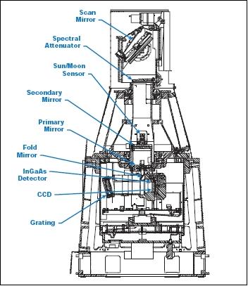
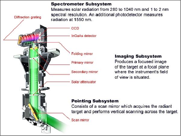
SAGE-III consists of three major subsystems:
1) Pointing subsystem: It consists of a scan mirror which acquires the radiant target and performs vertical scanning across the target. The scan mirror is mounted on an azimuth drive which rotates over 360º for pointing in azimuth direction.
2) Imaging subsystem. The objective is to produce a focused image of the target at a focal plane where the instrument's field of view is situated. - A Dall-Kirkham telescope design is used with an f/4 ratio. A slit (1/2 x 5 arcmin), located in the focal plane, serves as aperture and as entrance slit to the grating spectrometer. The entire telescope assembly, including scan mirror, can rotate in azimuth to eliminate the problem of image rotation during azimuth rotation. The target sensor assembly is mounted on the back of the telescope secondary and on the side of the telescope housing. The target sensor consists of a bi-level photodiode, capable to perform both solar and lunar acquisition with a change in dynamic range of six orders of magnitude.
3) Spectrometer subsystem. The objective is to measure solar radiation from 280 to 1040 nm and 1 to 2 nm spectral resolution. An additional photodetector measures radiation at 1550 nm. The spectrometer is a new design, utilizing a holographic, aberration-reduced grating to provide stigmatic imaging at 440 and 868 nm with 1 nm resolution below 450 nm and 2 nm resolution between 740 and 960 nm. The detector array consists of two elements, a Tektronix 800x10 pixel backside-illuminated CCD array (283-1030 nm range) and an infrared photodiode (InGaAs type for measurements at 1550 ±15 nm) that are spatially co-registered.
The spectrometer with the CCD array assembly provides continuous wavelength coverage between 290 and 1040 nm with a spectral resolution between 1.2 to 2.5 nm, permitting the measurement of multiple absorption features of each gaseous species and multi-wavelength measurement of broadband extinction by aerosols. Nine channels are routinely utilized in solar occultation measurements and three channels are used in lunar measurements. - Spectral calibration is continuous, combined with the self-calibrating nature of the occultation technique. In addition, the CCD array permits in-orbit wavelength and intensity calibration from observations of the exo-atmospheric solar Fraunhofer spectrum.
Cha. No. | Spectral center or range (nm) | Channel accuracy (nm) | No. of subchannels | Bandwidth at FWHM (nm) | Cut-off range (nm) | Integration time (ms) | SNR |
Solar Channels | |||||||
1 | 290 | ±1 | 1 | <5.0 | <7 | 2.23 | 3725 |
2 | 385 | ±1 | 1 | <14.5 | <17 | 0.26 | 6926 |
3 | 430-450 | ±0.5 | 20 | <1.1 | <3 | 0.11 | 2084 |
4 | 525 | ±1 | 1 | <10.5 | <13 | 0.09 | 7844 |
5 | 600 | ±1 | 1 | <10.5 | <13 | 0.10 | 7865 |
6 | 740-780 | ±1 | 20 | <2.2 | <5 | 0.17 | 3083 |
7 | 920-960 | ±1 | 20 | <2.2 | <5 | 0.58 | 3033 |
8 | 1020 | ±1 | 1 | <20.5 | <23 | 1.43 | 9678 |
9 | 1550 | ±5 | 1 | <32.5 | <23 |
|
|
Lunar Channels | |||||||
1 | 380-680 | ±0.5 | 300 | <1.5 | <17 | 62 | 160-300 |
2 | 740-780 | ±1 | 20 | <2.2 | <17 | 62 | 300 |
3 | 920-960 | ±1 | 20 | <2.2 | <17 | 62 | 150 |
|
| Solar Occultation | Lunar Occultation | ||
Wavelength (nm) | Constituent | Altitude (km) | Error (%) | Altitude (km) | Error (%) |
280 | O3 | 50-85 | 10 | - | - |
385 | Aerosol | 15-35 | 10 | - | - |
380-420 | OClO | - | - | 15-25 | 25 |
430-450 | NO2, Aerosol | 15-45, 10-35 | 10 | 20-50 | 10 |
470-490 | O3 | - | - | 15-35 | 10 |
525 | Aerosol | 6-35 | 10 | - | - |
600 | O3 | 6-60 | 5 | - | - |
640-680 | NO3 | - | - | 20-55 | 10 |
740-780 | O2, Aerosol, density | 6-70, 6-35 | 2 | - | - |
920-960 | H2O, Aerosol | 3-50, 3-35 | 10 | - | - |
1020 | Aerosol | 0-35 | 5 | - | - |
1550 | Aerosol | 0-35 | 5 | - | - |
Product name | Accuracy: | Vertical coverage |
Aerosol extinction at 8 wavelengths (solar) | 5% / 5% | 0-40 km |
H2O concentration | 10% / 15% | 0-50 km |
NO2 concentration & slant path column amount | 10% / 15% | 10-50 km, 10-50 km |
NO3 concentration (lunar) | 10% / 10% | 20-55 km |
O3 concentration & slant path column amount | 6% / 5% | 6-85 km, 50-85 km |
OClO concentration (lunar) | 25% / 20% | 15-25 km |
Pressure | 2% / 2% | 0-85 km |
Temperature profile (solar) | 2 K / 2 K | 0-85 km |
Cloud presence | N/A | 6-30 km |
The SAGE-III retrieval algorithm is a procedure converting the instrument's response to solar or lunar flux (about 70-80 spectral bands) into vertical profiles of molecular density of gaseous species, aerosol extinction at eight wavelengths, temperature, and pressure.
References
1) A. I. Bedritsky, V. V. Asmus, A. B. Uspensky, “Current and Future Russian Meteorological Satellite Systems and their Applications,” Proceedings of the EUMETSAT Meteorological Satellite Data User's Conference, Copenhagen, Denmark, Sept. 6-10, 1999, pp. 17-23
2) http://eospso.gsfc.nasa.gov/eos_homepage/mission_profiles/docs/Meteor-3M.pdf
3) “SAGE III – Meteor-3M,” URL: http://science.nasa.gov/missions/sage-3/
4) CEOS Handbook, URL: http://database.eohandbook.com/database/missionsummary.aspx?missionID=129
5) L. Mauldin, R. Salikhov, S. Habib, A. Vladimirov, et al., “Meteor-3M/Stratospheric Aerosol and Gas Experiment (SAGE-III) Jointly Sponsored by the National Aeronautics and Space Administration and the Russian Space agency,” SPIE International Asia-Pacific Symposium, Sept. 14-17, 1998, Beijing, China
6) V. Asmus, “Russian Environmental Satellites: Current Status and Development Perspectives,” CEOS Plenary Meeting, Colorado Springs, CO, Nov. 19-20, 2003
7) “Russian Weather Satellites: Mission Objective and Development Perspectives,” CEOS Plenary Meeting, Frascati, Italy, Nov. 20-21, 2002, URL: http://ceos.esrin.esa.it/plenary16/agencyreports/agencyreport_roshydromet.doc
8) “Space System METEOR-3M No1,” URL: http://planet.iitp.ru/english/spacecraft/meteor-3mn1.htm
9) A. S. Selivanov, Y. M. Tuchin, M. K. Naraeva, B. I. Nosov, “Experimental Satellite System for Earth Monitoring,” Issledovanie Zemli iz Kosmosa, W 5, 1981
10) I. V. Cherny, G. M. Chernyavsky, N. N. Gorobets, “Spaceborne Microwave Image/Sounder MTVZA,” Proceedings of 25th ESA Antenna Workshop on Satellite Antenna Technology, ESTEC, Noordwijk, The Netherlands, Sept. 18-20, 2002, pp. 523-527
11) I. V. Cherny, G. M. Chernyavsky, “Microwave Imager/Sounder MTVZA of Space Meteor-3M,” Proceedings of 7th International Conference on Remote Sensing for Marine and Coastal Environments, Miami, FLA, May 20-22, 2002
12) I. V. Cherny, G. M. Chernyavsky, V. P.Nakonechny, S. Yu. Pantsov, “Spacecraft ”Meteor-3M” Microwave Imager/Sounder MTVZA: First Results,” Proceedings of IGARSS 2202, Toronto, Canada, June 24-28, 2002
13) Courtesy of Igor V. Cherny of Space Observations Center of Roskosmos, Moscow
14) M. O. Riazantseva, E. E. Antonova, B. V. Marjin, V. V. Hoteenkov, I. L. Ovchinnikov, M. A. Saveliev, V. M. Feigin, M. V. Stepanova, “Auroral oval boundary observations by Meteor 3M satellite,” URL: http://ics8.ca/proc_files/riazantseva.pdf
15) V. D. Shargorodsky, V. P. Vasiliev, N. M. Soyuzova, V. B. Burmistrov, I. S. Gashkin, M. S. Belov, T. I. Khorosheva, E. Nikolaev, “Experimental Spherical Retroreflector on Board of the Meteor-3M Satellite,” URL: http://cddis.gsfc.nasa.gov/lw12/docs/Shargorodsky_et_al_Spherical%20Retroreflector.pdf
16) V. B. Burmistrov, N. N. Parkhomenko, V. D. Shargorodsky, V. P. Vasiliev, J. J. Degnan, S. Habib, V. D. Glotov, N. L. Sokolov, “Spherical Retroreflector with an Extremely Small Target Error- International Experiment in Space,” URL: http://cddis.nasa.gov/lw13/docs/presentations/target_parkhomenko_1p.pdf
17) V. B. Burmistrov, N. N. Parkhomenko, V. D. Shargorodsky, V. P. Vasiliev, “Reflector, Larets and Meteor-3M (1), what did we learn from tracking campaign results,” URL: http://cddis.nasa.gov/lw14/docs/papers/tar3a_vbm.pdf
18) A. M. Larar, “Optical Spectroscopic Techniques and Instrumentation for Atmospheric and Space Research III,” Proceedings of SPIE, Vol. 3756, July 19-21, 1999, Denver, CO, pp. 102-179
19) W. P. Chu, R. Veiga, “Overview of the SAGE-III Experiment,” Proceedings of SPIE, Vol. 3756, July 19-21, 1999, Denver, CO, pp. 102-109
20) http://www.ballaerospace.com/file/media/sage3.pdf
21) C. Trepte, M. Patrick McCormick, W. P. Chu, “Stratospheric Aerosol and Gas Experiment (SAGE) III Data Validation Plan,” LaRC 475-00-020, Version 4.0, November 2001, URL: http://badc.nerc.ac.uk/browse/badc/sage3/doc/sage3_Data_Validation_Plan.pdf
22) S. Burton, E.W. Chiou, W. P. Chu, M. S. Cisewski, D. Flittner, N. Iyer, J. R. Moore, D.F. Rault, A. D. Risley, G. Taha, L. W. Thomason, C. Trepte, J. M. Zawodny, Pat McCormick, “The Meteor3M/Stratospheric Aerosol and Gas Experiment III: A bridge to the future for long-term records of ozone and aerosol,” OPAC-3 (Occultations for Probing Atmosphere and Climate), Graz, Austria, Sept. 17-21, 2007, URL: http://wegc203116.uni-graz.at/OPAC3/pdf_presentation/opac3_david_flittner_32_presentation.pdf
23) W. P. Chu, C. R. Trepte, R. E. Veiga, M. S. Cisewski, G. Taha, “SAGE-III Measurements,” Proceedings of SPIE, Vol 4814, SPIE Annual Meeting 2002: Remote Sensing and Space Technology, July 7-11, 2002, Seattle, WA
24) W. P. Chu, R. Veiga, “SAGE-III / EOS,” Proceedings of SPIE, Vol. 3501, Sept. 15-17, 1998, Beijing, pp. 52-60
25) R. E. Veiga, W. P. Chu, A. J. Ray, “The SAGE-III Instrument and Level-1 Data Corrections,” ESAMS'99 European Symposium on Atmospheric Measurements from Space, ESTEC, Noordwijk, The Netherlands, Jan. 18-22, 1999,
26) “SAGE III Instrument,” URL: http://badc.nerc.ac.uk/data/sage3/instrument.html
27) “Stratospheric Aerosol and Gas Experiment III (SAGE III),” URL: http://badc.nerc.ac.uk/view/badc.nerc.ac.uk__ATOM__dataent_sage3
28) Yu. A. Borisov, T. V. Bankova, A. I. Ivanovsky, E. A. Chayanova, V. N Glazkov, “METEOR-3M/SAGE III: Algorithm, Results & Validation,” URL: http://www.isprs.org/publications/related/ISRSE/html/papers/957.pdf
29) P. McCormick, J. Anderson, W. P. Chu, C. R. Trepte, L. W. Thomason, J. M. Zawodny, “The SAGE III/Meteor Mission - One Year in Operation,” URL: http://www.atmosp.physics.utoronto.ca/SPARC/News21/21_McCormick.html
The information compiled and edited in this article was provided by Herbert J. Kramer from his documentation of: ”Observation of the Earth and Its Environment: Survey of Missions and Sensors” (Springer Verlag) as well as many other sources after the publication of the 4th edition in 2002. - Comments and corrections to this article are always welcome for further updates (eoportal@symbios.space).