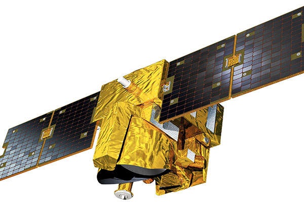
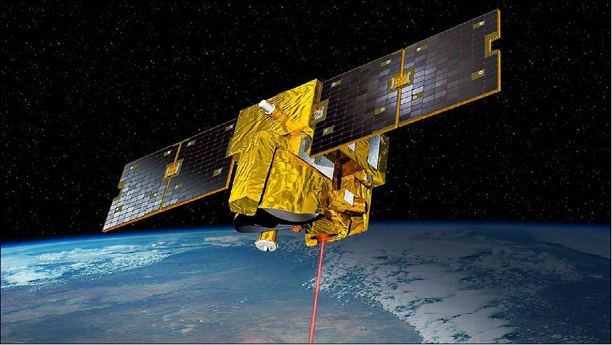
MERLIN (Methane Remote Sensing Lidar Mission)
EO
Atmosphere
Approved
CNES
MERLIN is a collaborative Franco-German minisatellite climate mission due to be launched in February 2028. The minisatellite aims to reveal the implications of methane gas on global warming and climate change.
Quick facts
Overview
| Mission type | EO |
| Agency | CNES, DLR |
| Mission status | Approved |
| Measurement domain | Atmosphere |
| Measurement category | Trace gases (excluding ozone) |
| Measurement detailed | CH4 Mole Fraction |
| Instruments | IPDA LIDAR |
| Instrument type | Atmospheric chemistry |
| CEOS EO Handbook | See MERLIN (Methane Remote Sensing Lidar Mission) summary |
Summary
Mission Capabilities
MERLIN will carry a single instrument onboard, an Integrated Path Differential-Absorption Lidar (IPDA LIDAR). IPDA LIDAR will use the laser light of a wavelength at the centre of the methane absorption line scattered back from the Earth’s surface, in comparison with a reference beam, to determine the column content of methane gas in the atmosphere. IPDA LIDAR is set to have unprecedented accuracy and precision of spatial and temporal gradients of atmospheric methane gas columns to thus contribute to research into the causes of climate change. Specific scientific performance requirements include the ability to resolve large wetland fluxes, inter-hemisphere gradients, seasonal and annual methane gas budgets on a continental and country-scale and Kyoto protocol-like monitoring.
Performance Specifications
IPDA LIDAR onboard MERLIN will aim to provide global coverage, resolving total columns with a 50 km horizontal resolution. Featuring a 10 m accuracy of measurement for scattering surface elevation, MERLIN will also target a Relative Random Error (RRE) of less than 8 ppb and a Relative systematic error of less than 1 ppb. MERLIN is set to undergo a near-polar sun-synchronous orbit of altitude 500 km, orbital period of 90 minutes and a repeat cycle of approximately 28 days. The satellite is designed to be compatible with a Local Time Ascending Node (LTAN) of 0600 and 1800 hours.
Space and Hardware Components
Developed by CNES, the MERLIN platform is an enhancement of a minisatellite from the Myriade platform series referred to as Myriade Evolutions. The 260 kg minisatellite platform has an increased solar array capacity and power distribution, an improved ACOS (Attitude and Orbital Control Systems), an increase of the payload data storage, and compatibility with low flight altitudes. To enable low altitude flight, a bi-compliant chemical propulsion system has been developed for green propellant and hydrazine fuels, to be used by its four 1N thrusters. With a total spacecraft mass of 430 kg, MERLIN will carry 28 kg of hydrazine fuel to support a design life of approximately three years.
Telemetry, Tracking and Command (TT&C) data will be transmitted in S-band at uplink rates of 16, 32 and 64 kbit/s and a downlink rate of 625 kbit/s. Payload data will be downlinked in X-band at 180 to 310 Mbit/s.
MERLIN (Methane Remote Sensing Lidar Mission) Minisatellite
Spacecraft Launch Sensor Complement Ground Segment References
MERLIN is a Franco-German collaborative minisatellite climate mission. The primary objective is to obtain spatial and temporal gradients of atmospheric methane (CH4) columns with high precision and unprecedented accuracy on a global scale.
Methane (CH4) and carbon dioxide (CO2) both cause global warming, although the impact of methane is 25 times more powerful than the one of carbon dioxide on a timescale of 100 years. Now, at a time when there is much discussion about mankind being directly responsible for the rise in the emission of greenhouse gases, methane emission levels already far outstrip carbon dioxide. Since pre-industrial times, the amount of methane in the atmosphere has more than doubled, whereas the growth in carbon dioxide levels during the same period has been 'only' thirty per cent. Methane is after carbon dioxide the strongest anthropogenic greenhouse gas. Methane emissions are caused by human activities as well as natural sources – for example, from rice paddies, animal husbandry, biomass decomposition, landfill sites or energy generation. Natural sources include swamps and marshlands as well as thawing permafrost. Alongside carbon dioxide, methane is one of those gases for which the Kyoto Protocol stipulates that cuts must be achieved. 1) 2) 3) 4) 5)
A major problem in the understanding of CH4 source- and sink-processes is the lack of precise global measurements of atmospheric CH4. Ground-based in-situ observations are insufficient because the existing measurement network is too coarse. Source regions of key importance to the global CH4 cycle such as the Arctic permafrost, Boreal forests and Tropical wetlands are difficult to access; hence, they are underrepresented or not sampled at all. Therefore, it is necessary to apply spaceborne measurement techniques in order to obtain global coverage at high precision. Today, GOSAT (Greenhouse Gases Observing Satellite) of JAXA has the ability to measure CH4 from space.
The observation strategy is based on measuring spectra of sunlight backscattered by the Earth's surface and atmosphere in the shortwave infrared spectral region. The main problem of these passive methods is that undetected aerosol layers or thin ice clouds produce systematic measurement errors of unknown magnitude, resulting from the complexity of the retrieval algorithms and the limited availability of independent measurements for validation. To counter these limitations, the use of active remote sensing instruments like the IPDA (Integrated Path Differential Absorption) LIDAR, was proposed.
The data that the MERLIN climate satellite will gather from orbit will enable scientists in both countries to draw conclusions about the various different sources of methane emissions.
What is the impact of rising levels of energy production?
What are the implications when tracts of permafrost release methane as they start to thaw?
Above all, what are the implications for our climate?
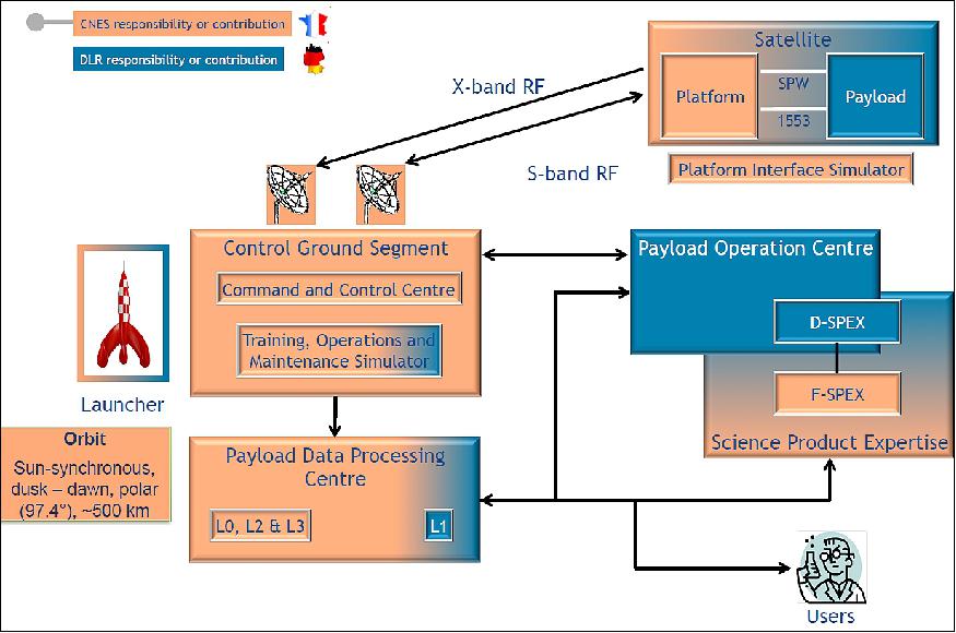
MERLIN is a joint mission by DLR (German Space Administration) and CNES (French Space Agency), where Germany is developing and building the methane LIDAR (Light Detection And Ranging) instrument, while France is providing the satellite platform Myriade Evolutions and the mission control. Joint data processing and science activities in France and Germany will be established.
Mission Organization (Ref.11)
The sharing of the Parties' undertakings schemed for the overall MERLIN project is as follows:
• CNES, as a system and satellite prime:
- leads system and satellite level activities, including the system architecture definition and the satellite design based on MYRIADE Evolutions platform
- manages the launcher activities based on a preference for European operators
- is in charge of the satellite CGS (Control Ground Segment) based on the new product line, the so-called ISIS (Initiative for Space Innovation Standard); this CGS using the CNES earth terminal network
- is responsible, on the PLGS (Payload Ground Segment) topic, for the development of the host structure, in which the operational data processing is implemented, and its exploitation, and the development and maintenance of the operational level 0, 2 and 3 operational data processors.
• DLR, as payload prime:
- leads payload level activities and some system-level activities, including payload development, until its integration on the satellite and its functional verification
- is in charge of the development, maintenance, and exploitation of the PLOC (Payload Operation Center) which consists of commanding, monitoring and expertise in the payload
- is responsible, in the PLGS scope, for the development and maintenance of the operational level 1a and 1b operational data processors.
The science activities are led by two Co-Principle-Investigators from the French LMD (Laboratoire de Météorologie Dynamique) of CNRS and the German DLR Institute for Atmospheric Physics, with additional support from several French and German Research Institutes.
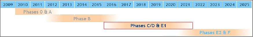
The MERLIN mission was initiated in February 2010, when the Franco-German Council of Ministers decided to start a minisatellite mission monitoring the greenhouse gas methane in the atmosphere. Phase 0 of the project started in early 2010. In the second quarter of 2012, MERLIN successfully finished Phase A. A launch is expected in the timeframe of 2021 with a minimum mission lifetime of 3 years on orbit. 6) 7) 8) 9)
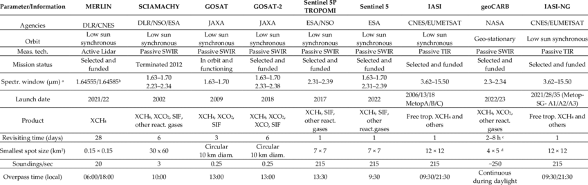
Table 1: Comparison of the MERLIN mission with other past, current, decided, or proposed missions measuring methane with characteristics that are suitable for source estimation. 10)
Legend to Table 1:
a) Only windows for CH4 detection are listed;
b) Online/offline wavelengths;
c) At continental scale;
d) Resolution at roughly 30º.
The resolution is degraded when latitude increases. SSO (Sun-Synchronous Orbit).
- German Space Agency (DLR); French Space Agency (CNES); SCIAMACHY (SCanning Imaging Absorption spectroMeter for Atmospheric CHartographY); GOSAT (Greenhouse Gases Observing SATellite); SWIR (ShortWave Infrared absorption spectrometry); NSO (Netherlands Space Office); ESA (European Space Agency); JAXA (Japan Aerospace Exploration Agency); TIR (Thermal Infrared); TROPOMI (Tropospheric Monitoring Instrument); SIF (Solar-Induced chlorophyll Fluorescence); NASA (National Aeronautics and Space Administration); EUMETSAT (European Organization for the Exploitation of Meteorological Satellites); geoCARB (geostationary Carbon cycle observatory); IASI-NG (Infrared Atmospheric Sounding Interferometer-New Generation).
Spacecraft
CNES is providing the MERLIN platform, a minisatellite of the Myriade platform series, referred to as "Myriade Evolutions". The Myriade Evolutions program is an enhancement of the original platform concept in order to improve the payload allocations in terms of power, mass, volume and reliability.
In fact, the main improvements are:
a) a new structure in order to reach 400 kg for satellite mass,
b) an increase in the solar array capacity and power distribution,
c) a newly adapted propulsion system,
d) an improved AOCS (Attitude and Orbital Control Systems),
e) an increase in the payload data storage,
f) the obsolescence handling,
g) compatibility with low flight altitudes (atomic oxygen concerns).
Initiated by CNES, this program is developed in partnership with Thales Alenia Space and Airbus Defence and Space, France. The first Myriade Evolutions platform is implemented for the MERLIN project. MERLIN aims at developing and qualifying the platform product line which will be available for the time frame 2015-2025. This product line will provide platforms for scientific, defence or industrial applications. As it's been for the previous product line MYRIADE, a low-cost, modularity which fits the mission needs and a short development schedule are the main assets of the Myriade Evolutions Program. 11) 12) 13) 14) 15) 16)
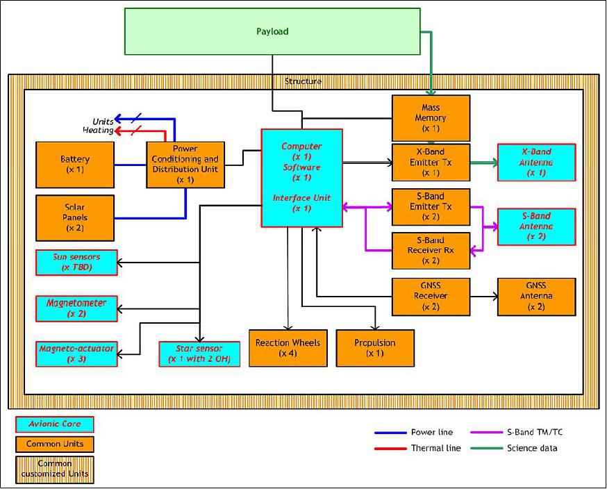
The Myriade Evolutions platform is a standard platform composed of a rectangular parallelepiped structure set up of:
• A Spacecraft Interface Ring which ensures the interface between the launcher and the satellite
• A rectangular box made of aluminium sandwich panels
- 4 lateral walls (that support equipment)
- a top floor (that supports the payload module)
- diaphragm panel –X (that closes the rectangular box) - Mechanical aluminium machined parts that connect panels together.
The chemical propulsion module is bi-compliant with green propellant and hydrazine. The module, based on 4 thrusters 1N allows positioning operations, in-orbit operation and deorbiting at the end-of-life phase.
The power subsystem is composed of:
a) a 2-wings solar generator,
b) a battery and new equipment for electrical conditioning and distribution.
Those elements are completed by 4 reaction wheels, 2 GNSS (GPS), 2 S-band transmitters for the telemetry (1 Mbit/s) and the telecommands (32kbit/s), a Payload Mass Memory and an X-band transmitter high rate (180 Mbit/s) for the science data. The equipment developed in the frame of Myriade Evolutions is aimed to equip the platform with an efficient and reliable product.
The avionic cores (onboard computer (OBC) and attitude and orbit control system (AOCS)) are based on the avionics upgraded from the existing product lines of each satellite contractor (ADS-F and TAS) in order to maximise the synergy between the low orbit satellite family. This choice ensures both the contractor of high knowledge and control of the product line.
To sum up, the Myriade Evolutions Platform is composed of a structure and 9 common units which are completed by the avionics and the AOCS equipment provided by the satellite contractor. Moreover, all those developments are conducted in conformity with the FSOA (French Space Operations Act) with embedded functions as end-of-life passivation (tank unpressured actions and electrical passivation).
In April 2015, Airbus Defence and Space signed a contract with CNES to build the platform and carry out the final integration of the MERLIN spacecraft. MERLIN is the first institutional program to be based on the new AstroBus-S platform, developed by Airbus Defence and Space in partnership with CNES, as part of the French Investment for the Future Program (Plan d'Investissements d'Avenir – Myriade Evolutions). AstroBus-S will form the basis of the Airbus Defence and Space range of 400 kg class Earth observation satellites for imaging, climatology and science missions. 17) 18)
Spacecraft launch mass | 430 kg |
Platform mass | 260 kg |
Platform size (stowed) | 570 mm x 980 mm x 1020 mm (external appendices not included) |
Power generation | 500 W, (platform + payload), 150 W allocated for payload |
Power units | Deployable solar array and battery |
AOCS elements | Star tracker, reaction wheels, .. |
Propulsion | 28 kg of hydrazine fuel |
RF communications | X-band downlink of payload data at 180 to 310 Mbit/s |
The Myriade Evolutions platform (Figure 2) is not compatible anymore with the Soyuz outer seat position. The satellite volume is constrained by the Soyuz inner seat position which is the most limiting of the anticipated potential launchers (European and non-European).
The Myriade Evolutions platform is based on two kinds of units:
• Units belonging to the so-named "common units", specified, developed and qualified by the Myriade Evolutions partnership (CNES, Airbus Defence and Space and Thales Alenia Space)
• Units belonging to the so-named "avionic core units", specified, developed and qualified by the satellite prime contractors (Airbus Defence and Space and Thales Alenia Space).
• MERLIN is the first satellite application of Myriade Evolutions and the second instantiation of the AstroBus-S platform.
Of course, the common units and the avionic core units are designed in order to guarantee trans-compatibility in terms of functions and interfaces.
The common units are specified and selected further to a European consultation. The avionics core is a heritage of the multi-mission version of avionics developed in the recent past by the French prime space industry (Airbus Defence and Space and Thales Alenia Space). These avionic cores, compliant with ISIS standards, ensure a high level of modularity with the payload interfaces.
The MERLIN satellite architecture is then based on the AS250 (AstroSat) avionics core and integrates all Myriade Evolutions common units, as shown in Figure 4.
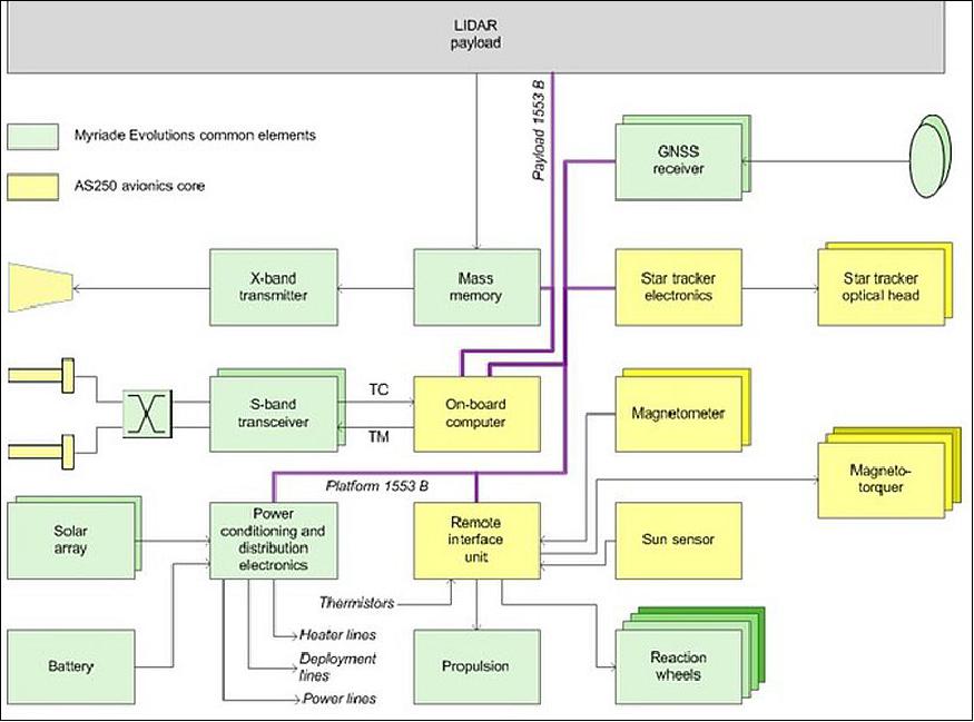
AOCS (Attitude and Orbit Control Subsystem)
The AOCS, selected for MERLIN mission, is the high-accuracy gyro-less version, fully inherited from Airbus Defence and Space flight-proven AS250 avionics (flown on SPOT-6 and SPOT-7) and based on a dual head Hydra star tracker. The equipment (actuators) coming from Myriade Evolutions are integrated into the AS250 AOCS with only minor changes at the level of major functional interfaces.
All other functional chains (electrical power, S-band, payload data handling and transmission, propulsion) are based on Myriade Evolutions units, and fulfil all the needs and performance requirements of the MERLIN mission. The resulting evolution of AstroBus S platform will be qualified for the MERLIN satellite, the first applicative mission selected by CNES for the Myriade Evolutions program.
The redundancy architecture can be tuned to meet mission requirements. For stringent missions, full redundancy can be accommodated. For the MERLIN case, a specific redundancy scheme is selected to meet CNES requirements. This limited redundancy scheme allows exceeding the MERLIN reliability requirement of 0.8 over the lifetime in orbit.
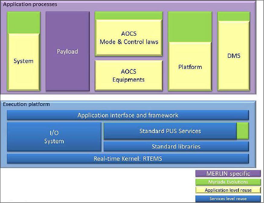
The Central Software architecture is based on a standard structure breakdown with a very high level of reuse from the AS250 product line. Thanks to this standardized architecture, mission customization is eased and affects only the higher application level.
RF communications: The TT&C data are transmitted in S-band at 625 kbit/s. The payload data are downlinked in X-band at 180 Mbit/s.
Mission Status
• June 2017: MERLIN shall be the first active mission in space dedicated to GHG (Greenhouse Gases). MERLIN will provide truly global and high-accuracy measurements of XCH4 to estimate CH4 fluxes at regional to continental scale. 20)
Random error (high frequency, uncorrelated errors) | < 22 ppb (for surface reflectivity 0.1 sr-1) |
Systematic error [slowly varying component, (e.g. orbital variations, | < 3 ppb |
Horizontal sampling accumulation | 50 km |
Objectives | - Seasonal and annual budgets on a country scale |
The very low level of systematic error aims at avoiding geographical biases in the XCH4 fields that could lead to uncertainties in fluxes | |
• On February 17, 2017, DLR and Airbus DS GmbH signed a contract for the design and construction phases of the German-French climate satellite MERLIN (Methane Remote Sensing LIDAR Mission). From 2021, this small satellite mission will measure the methane concentration in Earth's atmosphere to an unprecedented level of accuracy and thus contribute to research into the causes of climate change. 21)
- The contract was signed at the Airbus site in Ottobrunn and includes the German contribution to the mission – namely, the development and construction of the methane LIDAR (Light Detection And Ranging), the measuring instrument on board the MERLIN satellite. The core part of the instrument is a laser, which can send out light pulses on two different wavelengths and thus measure the methane concentration at all latitudes with great precision regardless of sunlight.
• December 08, 2015: At the 2015 UN Climate Change Conference COP 21 in Paris, the German Aerospace Center (Deutsches Zentrum für Luft- und Raumfahrt; DLR) and the French space agency (CNES) met to reaffirm their commitment to jointly develop the MERLIN (MEthane Remote sensing LIdar missioN) satellite that is set to measure concentrations of methane in Earth's atmosphere with unprecedented accuracy. 22)
• The MERLIN project is currently (2014) in phase B: preliminary design. The MERLIN feasibility was demonstrated in phase A, it was shown that it is possible to operate a complex IPDA LIDAR instrument on a Myriade Evolutions small satellite platform. Thanks to the new Myriade Evolutions capacities, the payload needs for power, volume, mass, and pointing are met. In its current configuration, MERLIN reaches the scientific threshold requirements for the DAOD and is thus compliant with the demands of the scientific USR (User Requirement Document). The major milestones foreseen for the rest of the development are listed in Table 5.
Satellite PDR (Preliminary Design Review) | June 2015 |
Payload PDR | September 2015 |
Payload CDR (Critical Design Review) | April 2017 |
Satellite CDR | September 2017 |
Launch | December 2021 |
Launch
A launch of MERLIN as a secondary payload is expected for 2021/22 on a Soyuz ASAP-P launcher of Arianespace from Kourou.
Orbit: Sun-synchronous near-circular orbit, altitude ~506 km, inclination = 97.4º, LTAN (Local Time on Ascending Node) = 6:00 hours or 18:00 hours, repeat cycle = 28 days (Ref. 10).
Orbit definition: An important aspect of mission design is orbit selection. For MERLIN, a near-polar SSO (Sun-Synchronous Orbit) with an orbit height of about 500 km, a LTAN (Local Time Ascending Node) of 06:00 or 18:00 hours (as shown in Figure 9) and a repeat cycle of about 28 days is foreseen. 23)
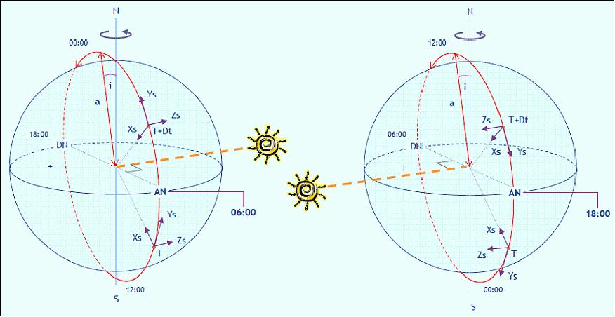
Due to a potential late LTAN choice, the satellite (platform and payload) must be designed to be compatible with both orbits at 06:00 and at 18:00 hours; this aspect is a main driver for satellite definition. Because of the low altitude of the mission, a large amount of fuel is dedicated to semi-major axis maintenance. This propellant needs highly depends on solar activity. A large uncertainty exists in the prediction of future solar activity. Sizing and typical predictions are used for fuel budget estimation.
Sensor Complement
IPDA (Integrated Path Differential-Absorption) LIDAR
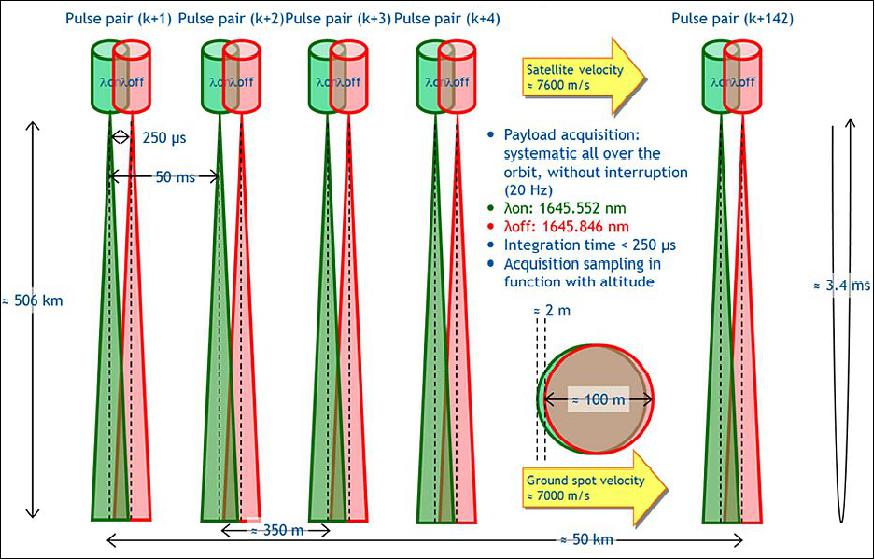
Measurement principle: An IPDA LIDAR uses the laser light scattered back from a surface to obtain measurements of the column content of a specific atmospheric trace gas between the instrument and the scattering surface. For this, the difference in atmospheric transmission between a laser emission with a wavelength placed at or near the centre of a CH4 absorption line (λon) and a reference wavelength (λoff) with significantly less absorption is used. A telescope collects the backscattered photons and focuses them onto the detector. Since the return signals are very weak, it is necessary to accumulate several single measurements of the return signals along the track in order to achieve the required measurement sensitivity. From the ratio of the two return signals, the DAOD (Differential Atmospheric Optical Depth) can be calculated. 24) 25) 26)
The goal of the MERLIN mission is to measure the spatial and temporal gradients of atmospheric CH4 columns with high precision and unprecedented accuracy. The main data product of MERLIN will be column-weighted dry-air mixing ratios of CH4, (XCH4) measured along the subsatellite track according to equation 1:
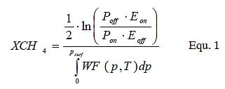
with the received signal powers Poff and Pon, normalized by the associated ratio of transmitted pulse energies Eon and Eoff. Psurf is the surface pressure at the location where the laser beam hits the ground and WF is the weighting function describing the altitude sensitivity of XCH4.
In order to provide a solid scientific basis for the mission, the scientific performance requirements were formulated. They are based on the random and systematic error of the instrument (Table 6). The requirements were chosen in such a way that the following quality levels can be reached: to resolve large wetland fluxes, inter-hemisphere gradients, seasonal and annual budgets on the continental scale (threshold), to resolve the seasonal and annual budgets on the country scale (breakthrough ), highest Methane flux estimate quality, and the Kyoto protocol like monitoring (goal).
Parameter | Target | Breakthrough | Threshold |
Data product | XCH4 | ||
RRE (Relative Random Error) | 8 ppb | 18 ppb | 36 ppb |
Relative systematic error | 1 ppb | 2 ppb | 3 ppb |
Coverage | Global | ||
Horizontal resolution | 50 km | ||
Vertical resolution | Total column | ||
Accuracy of scattering surface elevation | 10 m | ||
Instrument
The DLR instrument selected consists of an IPDA LIDAR. The industrial consortium, comprising Airbus DS GmbH (former Astrium GmbH, Ottobrunn) and Kayser-Threde GmbH, is realizing this LIDAR instrument, where Astrium is acting as the prime leader and is contributing the transmitter laser. Kayser-Threde is responsible for the optical receiver system and the signal chain. 27) 28) 29)
The main driver for the actual payload design is the limited payload allocations by the platform. The Myriade Evolutions platform provides a payload allocated power of about 110 W (during the eclipse phase) and can carry a payload with a maximum mass of about 95 kg in a volume of 82 cm x 88 cm x 92 cm.
Aside from these platform constraints, the main driver for the instrument design is the necessity to reach the scientific requirements. The RRE (Relative Random Error) is mainly driven by orbit altitude, the size of the receiver telescope and the available laser pulse energy. The minimal orbit altitude is limited by the platform (due to atomic oxygen constraints), the maximum telescope size is due to volume allocations of the launcher and the pulse energy is due to power allocations by the platform. Aside from the random error, the RSE (Relative Systematic Error) has also to be taken into account. This error depends mainly on the accuracy and stability of the energy calibration, stability and knowledge of the laser frequency, stability and knowledge of pointing and detector linearity.
The industrial consortium, comprising Astrium GmbH and Kayser-Threde GmbH, is realizing this Lidar instrument, where Astrium is acting as the prime leader and is contributing with the transmitter laser. Kayser-Threde is responsible for the optical receiver system and the signal chain. 30) 31) 32)
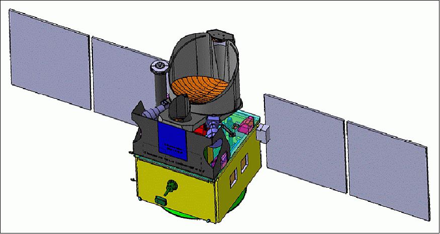
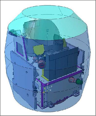
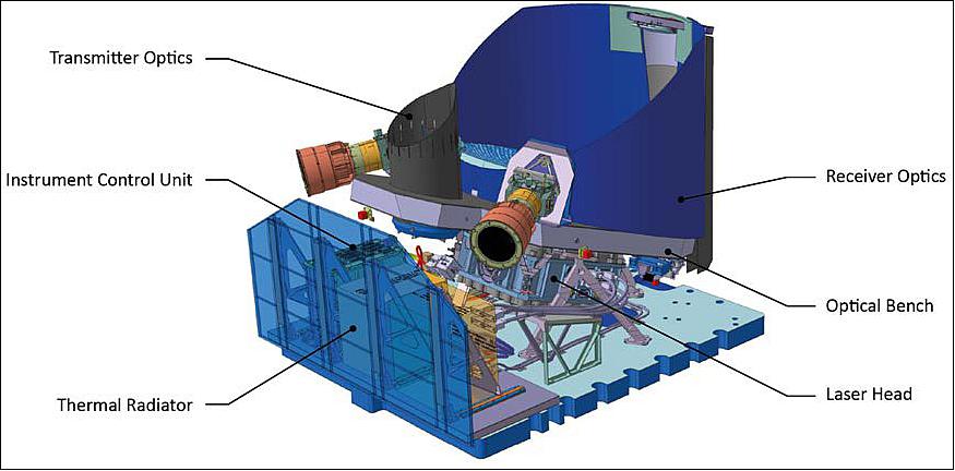
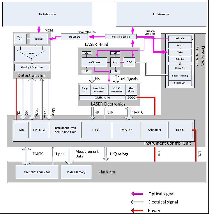
The IPDA LIDAR instrument uses two separate telescopes for the transmission (TX) and reception (RX) of the laser. Both telescopes are mounted on the same optical bench, which accommodates also the laser source unit, the detector chain as well as two-star trackers for verification and control of the pointing.
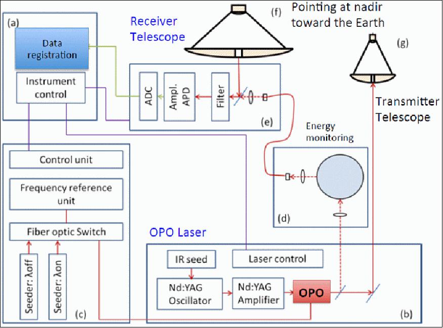
The basic scheme of the instrument is shown in Figure 10. Its main components are (Ref. 11):
• Instrument control unit (a)
• Laser transmitter (b)
• FRU (Frequency Reference Unit) (c)
• Energy calibration unit (d)
• Receiver chain (e)
• Receiving telescope (f)
• Transmitter telescope (g)
One of the MERLIN mission's main challenges is implementing a complex LIDAR instrument on a small satellite platform with limited resources. MERLIN will be the first satellite-based IPDA LIDAR system.
Important aspects for the selection of the subsystems are:
a) power consumption,
b) mass and volume allocations,
c) thermal behaviour,
d) radiation hardness.
The main parameters of the MERLIN instrument can be found in Table 2.
Payload mass, power allocation | 140 kg, 150 W |
Payload size | 820 mm x 830 mm x 1010 mm |
Laser pulse wavelength | On-line λon : 1645.552 nm |
Pulse energy | 9 mJ |
PRF (Pulse Repetition Frequency) for double pulses | 20 Hz |
Receiver telescope diameter | 690 mm |
The main structural element of the payload is the optical bench, made of UHM (Ultra High Modulus) CFRP (Carbon Fiber Reinforced Plastic) and designed for maximum stiffness and lowest CTE (Coefficient of Thermal Expansion), and sporting a tower for the M2 mirror of the RX telescope. Primary and secondary mirrors of both the TX and the RX telescope are made of Zerodur (Ref. 28).
The aim of the optical bench is twofold:
1) on one hand, it is meant to ensure a proper operational alignment of the two telescopes with the start tracker,
2) on the other hand, it thermally and thermoelastically decouples the payload from the platform for greater stability.
The choice of a design using UHM CFRP with epoxy resin, coupled with Zerodur mirrors, has been made based on uncertainties on the operational thermal environment (both in terms of absolute temperature and gradients), which are strictly related to the choice of totally passive thermal control for the payload.
In fact, the implementation of an active control would have been hardly feasible due to limitations in the power available to the payload. Of course, this does not exclude that other solutions, e.g. based on silicon carbide, would have been possible too: in fact, within a DLR contract, the involvement of a German material supplier (i.e. Schott AG) for Zerodur represents an additional programmatic advantage on top of technical considerations.
The optical bench is connected to the bus via three isostatic mounts: two long mounts in –z direction, and one short support in +z direction, providing the needed thermoelastic and thermal decoupling. The design of the isostatic mounts is stiff in axial and tangential direction; their orientation and accommodation do not follow a classic 120º spacing but are trimmed mainly to satisfy the interface requirements imposed by the platform, still avoiding conflicts with other payload elements or the use of asymmetric configurations. In particular, it is highly desirable to place all mechanical interfaces between the payload and platform as close as possible to the edges of the platform's top floor, since such locations benefit from the stiffening of the platform side panels.
The slanted position of the baseplate matches the angle of the TX-M1 mirror, which has a constant thickness and a flat backside for easier manufacturing and verification. The orientation of the baseplate enables the use of identical isostatic mounts for the TX-M1 mirror, with considerable advantages from the thermoelastic point of view (no rotations of the mirror in the case due to global temperature changes).
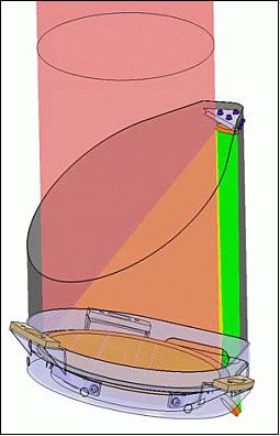
The receiver telescope uses an afocal design with a magnification of 50 x. It consists of two conical mirrors and an achromatized collimator lens, which generates an image of the entrance pupil with a size of 13.8 mm x 74 mm behind the lens. A design driver has been a compact envelope with a maximal M1-M2 mirror distance of 470 mm, allowing the M2 partly to vignette the entrance pupil. The telescope, together with the collimating lens group has been designed for both 1.645 µm and 633 nm, in order to allow operation and alignment in the visible wavelength range.
The RX-M2 tower consists of a stiff sandwich with CFRP skins. It is directly connected to the optical bench via dedicated bonded brackets. The shape is determined as the best compromise between stiffness, thermoelastic performance and ease of manufacturing. The baffle of the RX telescope is a thin structure out of a light material, e.g., a CFRP laminate. While no stringent requirements on the eigenfrequency of this structure apply, due to the limited mass, stiffening rings are planned to keep a correct shape and avoid strength issues e.g. during acoustic tests. As the optical system is relatively insensitive to straylight, the baffle has mainly a thermal function. The shape of the baffle closely follows the RX beam to maximize such function.
TX telescope:
The RX chain clearly dominates the design of the payload due to the larger complexity and physical dimensions. Most of the work has been therefore focused on the RX path, in order to soon identify critical aspects in terms of feasibility or system performance. Nevertheless, the study of the TX telescope can not be neglected. It consists of a separate structure with a ~220 mm M1 mirror; a CFRP baffle is used also as a structural element and supports the TX-M2. In this way, the baffle lends the spacer function between M1 and M2 and no additional structures are used, with positive effects on the resulting total mass.
The CFRP baffle and the TX-M1 mirror are supported by an Invar ring-shaped component that is directly connected to the optical bench. The Invar ring lends interfaces for the mounting of the Active Pointing Control mechanism, which folds the laser beam from the laser to the TX-M2 mirror.
- Similarly to what was done for the RX-chain, the CFRP baffle sports a slanted cut in order to avoid sun illumination into the telescope during nominal operation.
The remaining elements of the payload [radiators, FRU (Frequency Reference Unit), Laser Electronics and ICU (Instrument Control Unit)], as well as the antenna tower, are mechanically interfaced and supported by the platform. The FRU and the ICU, together with the laser, are the main dissipating sources and are thermally coupled with the payload radiators. 33)
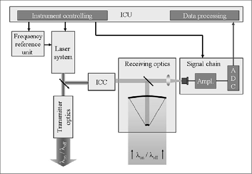
The functional MERLIN payload architecture is illustrated in Figure 14 and consists of three main functional parts: The receiver chain, including the receiver (RX) telescope, internal power calibration and the detection unit, the transmitter chain, including the transmitter (TX) telescope, the laser head and laser electronics, the frequency reference unit, and the ICU (Instrument Control Unit).
Laser:
As experiences and problems encountered in other missions like EarthCARE (Earth Clouds, Aerosols and Radiation Explorer) and ADM-Aeolus (Atmospheric Dynamics Mission) demonstrate, the design and realization of spaceborne lasers are rather sophisticated and involve several risks which have to be taken into account. These risks are mainly contributed to stable operation under space conditions and lifetime aspects of components. In contrast to the ALADIN instrument (Atmospheric Laser Doppler LIDAR Instrument) of the ADM-Aeolus mission, the laser used for the MERLIN mission is not a completely new development but deduced from the ESA EQM (Engineering Qualification Model) FULAS (Future LAser System) which is currently under construction.
The first step in the laser design was the selection of the appropriate measurement wavelength which depends mainly on these factors:
a) CH4 absorption bands,
b) detector efficiency,
c) eye safety considerations.
In the SWIR (Short-Wave Infrared) spectral range, where eye safety considerations are less critical, the CH4 lines are abundant, but the presence of water vapour and carbon dioxide lines drastically constrains the selection. Essentially two atmospheric water vapour transmission windows around 1600 and 2300 nm allow CH4 measurements. The detector performance is significantly better in the 1600 nm region where low-noise photodiodes (InGaAs APDs) are available. Since no directly pumped laser at this wavelength is available up until now, or its technology level is too low for consideration, a laser concept based on a Nd:YAG pumped OPO (Optical Parametric Oscillator) was selected.
The laser concept is based on a two-stage concept comprising a single frequency high power Nd:YAG master oscillator power amplifier (MOPA) stage which generates ns pulses at a wavelength of 1064 nm (Figure 15). The temporal, spectral and geometrical properties of the pump beam at 1064 nm are generated in a low-power frequency stabilized oscillator. This beam is amplified in the subsequent amplifier stage which optimally only increases the pulse energy without changing the other properties. The output is then converted into the final wavelength of 1645 nm in a second stage using a nonlinear converter. The most established technology for conversion is an OPO. This architecture has been demonstrated by different groups in various flight campaigns.
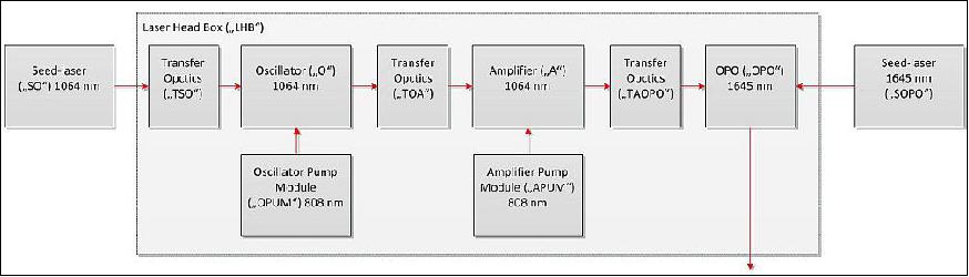
The pump laser will consist of a seeded oscillator followed by a single-end pumped slab amplifier. The oscillator design includes an end-pumped rod-crystal as the gain medium. The oscillator will be injection seeded and cavity controlled in order to achieve single longitudinal mode operation and to fulfil the stringent requirements on pulse quality. For the amplifier, the so-called InnoSlab concept, developed by the Fraunhofer Institute for Laser Technology, will be used. For the amplifier, the so-called InnoSlab concept, developed by the Fraunhofer Institute for Laser Technology, will be used (Figure 16). This concept is ideal for high-energy and high-efficiency power amplifiers for single-mode operation.
For MERLIN, the slab crystal is partially end-pumped from one end. This gives the advantage that only two faces of the crystal need to be optically polished. The heat dissipates very efficiently and homogeneously over 2 metal heat sinks soldered to the large faces of the crystal. The four optically unused surfaces of the crystal are roughened to optimally prevent internal parasitic laser oscillations.
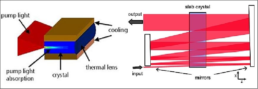
The four optically unused surfaces of the crystal are roughened to prevent internal parasitic laser oscillations optimally. To operate the InnoSlab laser as an amplifier (right part of Figure 16), the signal beam is folded in a single-pass configuration through the crystal. By choosing appropriate mirror radii and signal beam divergence, the beam is widened with every pass, and the fluency can be kept constant and remains far away from the damage threshold. By adapting the slab crystal width and the number of passes the InnoSlab amplifier is scalable in its output power. The MERLIN amplifier will be designed to deliver an output pulse energy of about 30 mJ at 1064 nm while the peak fluency will be smaller than 2.5 J/cm2. Simulations showed that this output energy is the best compromise between the strain of the pump modules and the efficiency of the pumped OPO.
The baseline for the OPO is a 4-mirror 2-crystal setup. The DLR airborne demonstrator for the DLR Jet HALO (High Altitude and Long Range Research Aircraft) also implements the same setup. The crystal will be either KAT (Potassium Titanyle Arsenate) or KTP (Potassium Titanium Oxide Phosphate). Like the oscillator, the OPO will be injection seeded and cavity controlled in order to achieve single longitudinal mode operation.
The practical realization of the MERLIN laser transmitter is based on the results of the FULAS (FUture LASer) project that has been initiated by ESA, in cooperation with DLR, to develop and built a technology demonstrator and to verify its suitability for potential space missions. In order to cover the common need of possible future LIDAR missions, requirements for a generic laser source had been defined to achieve maximum usability of the laser concept and technology for future LIDAR missions. 34)
FULAS is built as a pressurized and hermetically sealed housing with an isostatic mounting I/F for accommodation.
As shown in Figure 17, the housing central main frame provides several hermetical feed-throughs for electrical and optical connectors, thermal-hydraulic feed-throughs for miniature LHPs (Loop Heat Pipes) and a beam exit window. An external cold plate attached to the central frame of the housing serves as a condenser for the LHPs and as an overall system thermal I/F. The mounting of the laser optical bench is optimized for decoupling from the surrounding structure. By isostatic mounting inside the housing central frame, the optical bench is insulated from stress induced by the instrument environment. Particularly it features a maximum tolerance with respect to mechanical deformation due to environmental pressure changes.
Due to the need for a lightweight design, while providing thermal conductivity to support thermal balancing, aluminium was the material of choice for the housing. To provide access to both sides of the double-sided optical bench, a symmetrical open frame is used, carrying the optical bench. This frame is closed by two symmetrical bolted covers, primary-sealed by special metallic gaskets, enabling easy reopening and resealing during assembly and testing. For final lifetime sealing, the covers are designed to be welded, providing a reliable redundant secondary sealing.
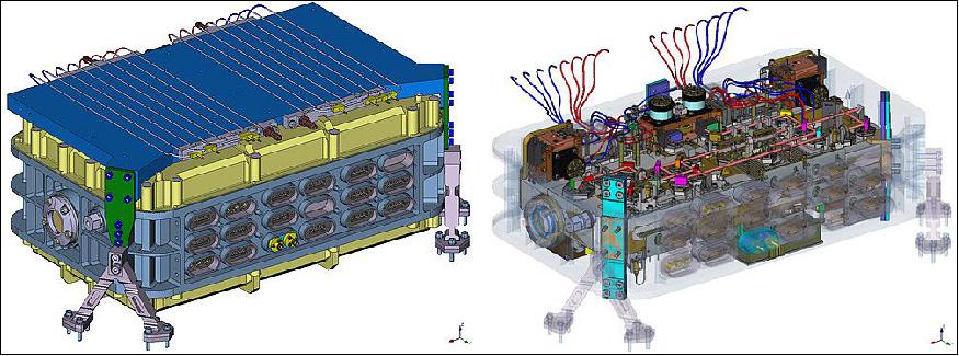
The challenging part of the design is the need for a multitude of various feed-throughs (electrical, thermal and fibre-optical) to operate such a system, as well as a high-quality optical beam exit window. To fulfil the cleanliness and lifetime requirements, only thermal joining methods such as welding, brazing or glass/ceramic potting are applicable. For brittle materials like glass, a CTE-matched joint is necessary, which typically leads to low CTE metals like stainless steel or titanium, not compatible with an aluminium housing and conventional joining technology. However, the applied mechanical friction stir welding (FSW) process, developed by the Airbus Group in the frame of the FULAS project, overcomes this incompatibility of the materials.
To allow an efficient rejection of the thermal load inside the pressurized housing and minimize thermal gradients across the optical bench, mini LHPs are directly attached to units inside the laser housing. Four pairs, each operated in one-out-of-two cold-redundancy configuration, are connected with their evaporators directly to the main heat sources on the optical bench, enabling selective cooling directly at the source. By its semi-rigid tubing combined with dedicated housing feedthroughs, the heat is efficiently transported out of the housing towards the external cold plate. Due to the low mechanical stiffness of the tubes the optical alignment and the mechanical decoupling of the optical bench is conserved and not affected by the thermal I/F.
The laser optical bench is mounted inside the pressurized housing central frame by use of isostatic mounts. The laser is assembled on both sides of the bench, as shown in Figure 17. The lower side carries the oscillator, while the power amplifier and the frequency conversion are situated on the upper side. In order to realize an efficient and compact space-borne laser, new mounting technologies like soldered optics will be applied. This allows a compact, precise, stable and glue-free mounting of the optical laser components. These specially designed mounts have been developed within a DLR-funded research project.
Calibration devices:
High laser stability and the actual knowledge of the laser frequency are crucial for this kind of instrument. Hence, a compact and precise frequency reference is necessary. To minimize the required amount of instrument equipment, it is highly desirable to use the frequency reference not only for absolute frequency monitoring but also to generate error signals for control of the OPO and the seed lasers.
The current approach for MERLIN is to use an air-spaced Fizeau interferometer and a CCD detector row for fringe measurements. Verification and also calibration are possible by ground echo calibration (determination of the spectral CH4 line centre from scanning its spectral line shape). Preliminary studies show that for the maximum rms deviation of the seed frequencies from their required absolute values, the following values must be reached: the online signal must provide an absolute stability of ~15 MHz rms over a lifetime while the offline signal must provide an absolute stability of ~100 MHz rms over the mission lifetime.
An IPDA LIDAR is solely relying on the measurement of relative signal intensities. The intensity of the recorded return signal is a direct function of the emitted laser pulse energy. Even for very good lasers, this variation is in the area of up to 5%. Therefore, it is necessary to monitor the energy of each emitted laser pulse with high accuracy and to correlate with the intensity of the corresponding optical return signals (equation 1).
To generate these internal calibration signals, a small fraction of the emitted laser pulses is extracted and fed directly through an attenuation stage to the instrument detector. Measuring the return and calibration signal with the same detector ensures that variations within the signal chain are eliminated. The challenge here is that because of the very weak return signal (for λon ~1000 photons per shot), the reference signal has to be attenuated by about 14 orders of magnitude.
Receiver:
Aside from the laser, the receiver telescope is the most challenging component of MERLIN. Its field of view has to be large enough so that the complete laser ground spot (150 m for 99% of the encircled energy) and additional margin for the satellite and the laser jitter are within this field. The other limiting factor is the size of the detector. For APD (Avalanche Photodiode) detectors, the noise is increasing drastically with the detector area, which means that a detector with a small active area has to be chosen. Furthermore, the overall height of the telescope is strongly limited due to the available space within the launcher fairing (MERLIN baseline: Soyuz ASAP-S inner position).
These factors result in a small F-number and thus a complex optical design. Aside from the size, also the mass is a very critical value. To realize such a telescope, serious light-weighting of about 85% has to be applied. Furthermore, the thermal design of the telescope has to be in such a way, that a purely passive thermal control system is sufficient since no extra power for heating is available. The current baseline for MERLIN is a Zerodur off-axis telescope with an aperture of 690 mm and an F-number of 0.65, mounted on an optical bench made of CFRP (Carbon Fiber Reinforced Plastic).
Due to the limited pulse energy and telescope size, the receiver and detector noise are both critical. The detector and the following amplifier stages have to be as noiseless as possible. In the 1650 nm region, InGaAs ADPs seem to be the most promising candidates and are currently the baseline for MERLIN. Also, MCT detectors are very promising candidates. They may offer some interesting features of interest for low light level detection around 1.65 µm due to their low excess noise.
ICU (Instrument Control Unit):
The ICU is the sole control instance for the whole instrument and interface between the platform and the payload.
Its main tasks include:
a) scheduling of the laser trigger,
b) control of the APD sensor data acquisition and buffering,
c) detector temperature control,
d) payload FDIR (Fault Detection, Isolation and Recovery) support,
e) telecommand decoding and execution,
f) calculation of the range gate according to the altitude data received from the platform.
Ground Segments
Besides the space segment, the other crucial part of the MERLIN mission is its ground segments. The MERLIN mission ground segment is composed of a CGS (Control Ground Segment) and a PLGS (Payload Ground Segment).
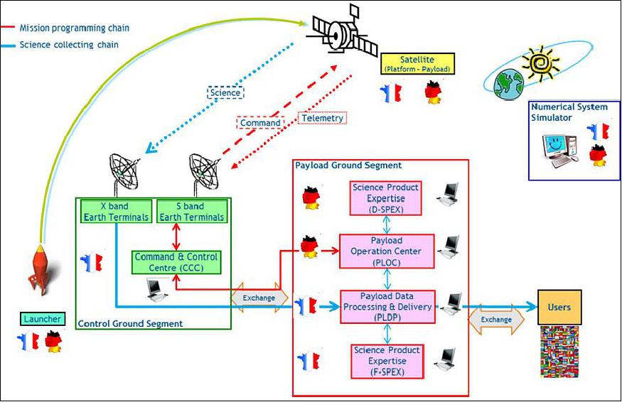
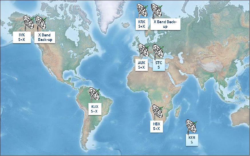
The ISIS command & control reusable ground segment is based on the ISIS generic operation concept and interfaces definition that will be used by all CNES missions in the future. Its main tasks are to control and monitor the satellite and ensure its health over the mission lifetime. The CNES Earth terminal network is based on stations implemented in Europe, Africa and America. It will be used for commanding and receiving housekeeping data (S-band terminals), and for downloading the science data (X-band terminals). The ground station network is under improvement in automation and reliability aspects (Ref. 11).
The CGS includes the following components and services: 35)
• A CCC (Command and Control Center) on the CST (CNES Site in Toulouse)
• An S-band and X-band telemetry and command function which uses the CNES network of TT&C ground stations
• Additional support functions provided by CNES multi-mission services:
- Debris management service for collision risk computation
- Orbit computation service
- Main control room (used occasionally, mainly in LEOP and commissioning phases)
- File exchange service.
• A Numerical System Simulator.
Command and Control Center:
The CCC will be built on the basis of the ISIS (Initiative for Space Innovative Standards) generic Command and Control Center to be used by all future CNES missions. Its main tasks are to control and monitor the satellite and ensure it remains in good condition throughout the mission's lifetime.
The CCC is composed of seven specialized subsystems:
• The Automation subsystem manages all the activities and orchestrates CCC operations
• The Monitoring and Control subsystem is responsible for the telemetry and command function and communication with the TT&C ground stations
• The Flight Dynamics subsystem is in charge of flight dynamics calculations linked to attitude and orbit control
• The Data Store subsystem is in charge of storing and managing all the data received and produced throughout the mission's lifetime
• The Mission Operation Support subsystem provides dedicated services to support the mission including on-board software management, alert management, generation of reports and the management of external interfaces
• The Visualization subsystem is the graphical interface dedicated to mission monitoring; it can display real-time telemetry and data available in the Data Store
• The Infrastructure subsystem comprises a set of general services, such as time management, hardware and software management or internal and external communication.
Station network:
The CNES multi-mission stations network provides S-band and X-band data services. It will be used for satellite commands and the reception of satellite housekeeping telemetry (S-band), and, in X-band, for downloading science data. The location of the S- and X-band ground stations is shown in Figure 21. Network operations are managed by the Network Operations Center in Toulouse.
PLGS (Payload Ground Segment):
In order to process and later on use the collected MERLIN data, an efficient payload ground segment is necessary. The PLGS is responsible for payload operations, the end-to-end handling of MERLIN data and the production, quality control, dissemination and archiving of mission products.
It consists of:
• PLOC (Payload Operation Center):
PLOC is dedicated to payload monitoring and control. Payload operations are conducted by the PLOC, which acts as the central hub for mission planning; it generates payload commands, manages payload calibration and monitors payload health.
PLOC is composed of:
- PLMC (Payload Monitoring & Control) which monitors and controls the payload. The PLMC generates commands to control the payload based on inputs from the PLEX, analyses payload behaviour, investigates payload anomalies and checks the Level 1a data produced by the PLDP. It provides information to the SPEX (Scientific Products Expertise centres) which can deliver a new version of the Level 1 processor to the PLDP.
- PLEX (Payload EXpertise) which provides in-depth payload expert appraisal and off-line instrument support functions such as mission planning input, long-term monitoring, calibration, instrument configuration control, provision of procedures for off-line monitoring of housekeeping and measurement data.
• PLDP (Payload Data Processing centre):
PLDP is responsible for processing and delivering science data, that is to say, the generation of level 0 to level 3 data and products, and the dissemination of Merlin science data. The PLDP manages the data and product archives
• SPEX (Scientific Products EXpertise centres):
SPEX is dedicated to expert assessments of MERLIN science products. SPEX centres manage the science prototypes to support the development and testing of the reference processors. They deliver new versions of a reference processor to the PLDP and relay the reprocessing campaign required by the Science Advisory Group.
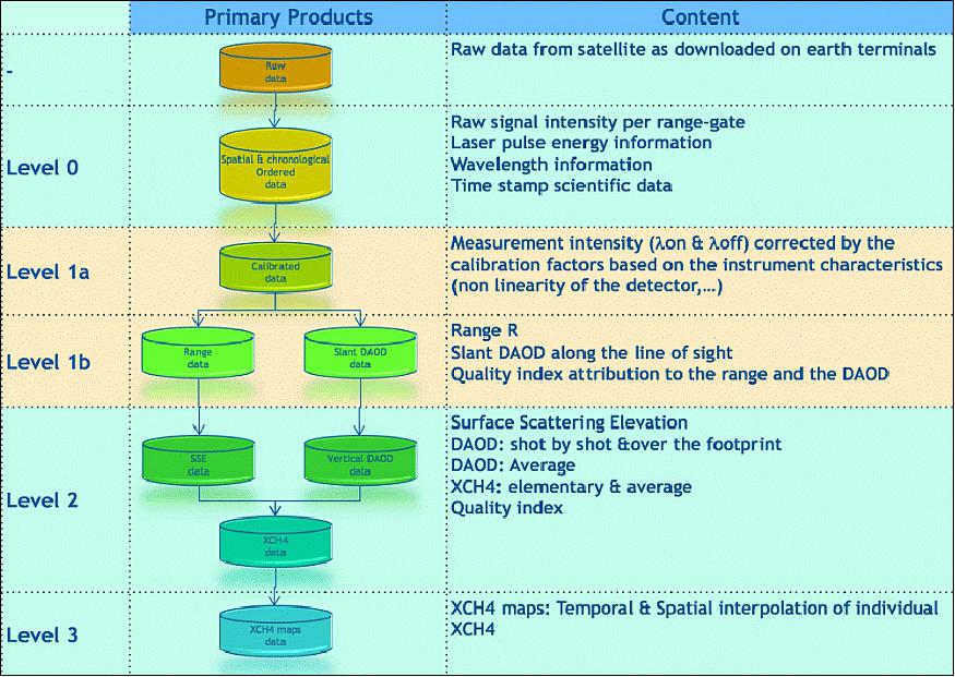
The MERLIN mission will provide the following data products:
• Level 0: for each individual laser shot the range-gated backscatter signal data including the ground returns and data from aerosols and clouds together with auxiliary data such as ranging information, laser pulse energy, time, and wavelength in a chronological data sequence for the payload operating in observation mode
• Level 1a: Level 0 data with all calibrations computed and appended, but not applied. The payload data are annotated from universal time, satellite position, velocity and pointing
• Level 1b: Level 1a data with radiometric calibrations applied, processed to get the mean nadir direction DAOD (Differential Absorption Optical Depth) and the mean SSE (Scattering Surface Elevation) corresponding to the required horizontal resolution. This data is annotated with information on observation-level calibration, preliminary pulse classification, geolocation and time
• Level 2: XCH4
• Level 3: visualizations of level 2 data such as XCH4 maps.
The level 0, 1 and 2 products are chronologically and spatially organized. In Figure 22, the processors' architecture including the product content is shown.
Various additional products can be derived from the observations of the MERLIN mission.
As a secondary product, MERLIN could provide estimates of the vegetation vertical structure, and its temporal dynamics with a view to obtain reliable extra constraints on the location and extent of land use change, especially deforestation and re-/afforestation activities. Estimates of the vegetation vertical structure also have the potential to improve knowledge of terrestrial above-ground biomass growth and its dynamics because there is a direct and increasingly better-understood statistical relationship to above-ground carbon storage.
A further secondary product of the MERLIN mission could be the detection of cloud boundaries, including a cloud base for small to moderate cloud optical thickness (≤ 1). MERLIN will be one of a number of anticipated next-generation LIDAR missions that will add to cloud climatology studies. The sensitivity to aerosol backscatter enables the detection of elevated aerosol layers associated with major forest fires, volcanic eruptions, and other biomass-burning activities on spatial scales that provide plume boundary information.
In-flight radiometric calibration of the LIDAR signals over sites with well-characterized reflectance properties could be convenient for comparison with LIDAR theoretical models in order to assess LIDAR performance. The LIDAR retro-reflectance includes the hot spot enhancement factor that applies to the broader angular reflectance normally observed using passive radiometers or imaging spectrometers.
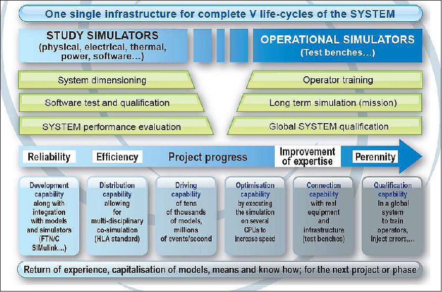
TOMS (Training, Operation and Maintenance Simulator)
A satellite simulator is aimed at modelling all the operational functions seen from the CCC (Control Command Center) through the housekeeping telemetry (TM) and the telecommand (TC).
The use of a Training, Operation and Maintenance Simulator (TOMS) allows (Ref. 16):
• the elaboration and the validation of the CCC
• the technical qualification of the system, including
- the validation of the programming plan (messages sent to the Payload) and the validation of the system's global performances
- the qualification and the validation of the onboard/ground interfaces.
• the operational qualification of the system
• the operators' training before and after the launch of the satellite
• the preparation and validation of exceptional operational procedures after the launch
• the anomaly investigation when a breakdown occurs after the launch.
To achieve those objectives, the TOMS, deployed at the CCC, has to substitute itself with the real satellite and the ground stations and make the operation teams based at the CCC believe they are communicating with the true satellite.
Architecture and Conception
A TOMS has to react as close as possible to the real satellite.
Then it is built around two types of components:
- An efficient simulation platform able to run tests faster than the real-time
- A set of numerical models representing each piece of equipment with a high level of representativeness.
At CNES, the TOMS components are all developed around a simulation infrastructure called BASILES (BAncs, SImulateurs et Logiciels d'Etudes de Satellites). But contrary to usual projects which integrate models from one or two suppliers, MERLIN has to undertake a challenge which consists in integrating models from four different suppliers: ADS-F (Airbus Defense and Space-France), Myriade Evolution, ADS-G and CNES.
1) BASILES Infrastructure:
BASILES is an open simulation infrastructure for the design, development and deployment of complex systems. It allows the representation of complex systems within discrete event simulation as well as integrating real equipment. Designed at first for numerical simulation of satellites, the BASILES components have been used in several space-related missions, for dimensioning space infrastructure, validation of hardware and software components, and technical and operational validation of global space systems and their components. BASILES has been designed to maintain continuity across disciplines, projects, phases and subsystems.
But BASILES simulation infrastructure, like all existing proprietary simulators, does not support natively SMP-2 ( Simulation Model Portability version 2) models. A model which is designed for BASILES must obey strict rules concerning the model structure to be compliant with the BASILES production tools so that it can be compiled, deployed and executed. And, the services provided by the kernel are specific to BASILES and cannot be used by models which only know of SMP-2 interfaces.
To overcome these limitations and to allow importing SMP-2 models and running SMP-2 simulations in the BASILES infrastructure, a software component has been developed to provide adaptation of the SMP-2 interfaces to the BASILES interfaces. The role of this component is to hide SMP-2 specifics to the infrastructure and allow integrating and running any SMP-2 compliant model into the BASILES infrastructure.
2) Avionic Core Numerical Models:
The MERLIN satellite development is supported by Airbus Defence and Space France and which then provides the avionics Core (OBC, RIU, STR, MTQ, MAG, CSS) according to the Myriade Evolutions organization. Accordingly, they are in charge of the development, qualification and delivery of all the associated numerical models for TOMS.
ADS-F uses its own simulation platform called SimTG (Simulation Third Generation) to develop and run the SMP-2 models. Most of the avionic core models for MERLIN are adapted from existing models, used on previous projects, which require few adaptations to be compliant with ISIS and SMP-2 standards.
In this context, MERLIN takes benefits of simulation standards which allow the exchange of models running on, on one side, SimTG for central software validation and functional chain validation and, on the other side, BASILES for TOMS uses. Besides reducing the integration risks on BASILES and securing the TOMS development schedule, ADS-F runs validation tests on both simulation platforms using two different validation environments (Java for SimTG and Tcl for BASILES).
On top of that, ADS-F provides all the physical models, the central software and the satellite database. The physical models enter the TOMS development process to qualify the simulator. The central software is integrated into the TOMS thanks to an emulator which allows simulating the exact behaviour of the satellite in terms of command/control and the satellite database is used to configure the models to avoid inconsistencies between simulation and real life
3) Myriade Evolutions Numerical Models:
The Myriade Evolutions project provides nine numerical models which correspond to the common units of the platform (Reaction Wheel, PCDU, GNSS, Mass Memory, Battery, Solar Generator, Propulsion, X-band Emitter, S-band Transceiver). By conception, those models are SSRA(Spacecraft Simulator Reference Architecture)/SMP-2 and ISIS compliant. Besides even if they are developed using UMF (Universal Modelling Framework) — SMP-2 conception tools developed by ESA, they are tested and validated on the BASILES infrastructure. The Myriade Evolutions development process ensures low-risk integration for TOMS development.
4) Payload Numerical Models:
The MERLIN Payload development is supported by Airbus Defence and Space Germany then provides the Payload Numerical Model. Based on specifications written by CNES (e.g. interface definition and expected representativeness), they develop the model using SimTG infrastructure as their French counterparts. And to ensure successful integration into the BASILES platform during TOMS development, they execute validation tests on both platforms SimTG and BASILES. Besides this model is deployed on the Payload Operational Center on simulation facilities and is used on the ADS-F bench to contribute to the central software validation. This model, as the previous ones, takes the benefit of intensive use in different environments to contribute to a high level of maturity when deployed on TOMS.
5) Common Patrimony Numerical Models:
CNES simulation department supports the ISIS approach by developing generic physical (Environment, Dynamics, Thermal) models which aim at being integrated on TOMS for MERLIN and all future missions. Those models have been specified taking into account the lessons learned and the needs of AOCS and Space mechanics teams to TOMS. They implement the ISIS and SMP-2 standards. Developed using UMF, they are tested on BASILES infrastructure based on data propagation concepts. The will is to have on shelves generic and easily configurable models which can be integrated without difficulty on BASILES to develop a TOMS.
In summary, MERLIN TOMS takes benefit of the lessons learned acquired on several projects over the past 10 years. It follows the standardization dynamics supported by CNES and its partners through ISIS and by ESA through SSRA and SMP-2. The implementation of those new processes allows for reducing costs, optimising the development schedules and contributes to making the system more efficient and reliable. MERLIN is proud to be the first project to support and implement the standardization for simulation activities and contribute in this way to the success of the mission.
Besides, the achieved works will lead to providing generic and modular solutions to future projects (SWOT, SVOM, etc.), optimising the development schedule, providing efficient validation facilities and ensuring a unique operational interface whatever the mission.
References
1) DLR, Sept. 8, 2010, URL: http://www.dlr.de/en/desktopdefault.aspx/tabid-3228/5011_read-22638/
2) Gerhard Ehret, Pierre Flamant, Axel Amediek, Philippe Ciais, Fabien Gibert, Andreas Fix, Christoph Kiemle, Mathieu Quatrevalet, Martin Wirth, "The French-German Climate Monitoring Initiative on Global Observations of Atmospheric Methane," ILRC 25 (25th International Laser Radar Conference), St. Petersburg, Russia, July 5-9, 2010, pp 1348-1351
3) C. Stephan, M. Alpers, B. Millet, G. Ehret, P. Flamant, C. Deniel, "MERLIN: a space-based methane monitor", Proceedings of SPIE, Optics and Photonics Conference, Vol. 8159, 815908, 'Lidar Remote Sensing for Environmental Monitoring XII,' San Diego, CA, USA, Aug. 21-25, 2011; doi:10.1117/12.896589
4) P. H. Flamant, G. Ehret, P. Bousquet, J. Marshall, B. Millet, M. Alpers, C. Pierangelo, C. Stephan, MERLIN: a new Franco-German 'MEthane Remote sensing LIdar missioN'," Proceedings of the IWGGMS-10 (10th International Workshop on Greenhouse Gas Measurements from Space) ESA/ESTEC, The Netherlands, May 5-7, 2014, URL: http://www.congrexprojects.com/2014-events/14c02/programme
5) C. Pierangelo, B. Millet, F. Esteve, M. Alpers, G. Ehret, P. Flamant, S. Berthier, F. Gibert, O. Chomette, D. Edouart, C. Deniel, P. Bousquet, F. Chevallier, "MERLIN (Methane Remote Sensing Lidar Mission): An Overview," EPJ (European Physical Journal) Web of Conferences, Vol. 119, 26001 (2016), DOI: 10.1051/epconf/201611926001, ILRC 27 (27th International Laser Radar Conference), URL: http://www.epj-conferences.org/arti
cles/epjconf/pdf/2016/14/epjconf_ilrc2016_26001.pdf
6) "French/German Climate Mission MERLIN, Measurements of Atmospheric Methane from Space," DLR, URL: http://www.dlr.de/rd/Portaldata/28/Resources
/dokumente/re/MERLIN_Datenblatt.pdf
7) Gerhard Ehret, Pierre. H. Flamant, "The French/German Climate Mission MERLIN," Proceedings of IGARSS (International Geoscience and Remote Sensing Symposium), Munich, Germany, July 22-27, 2012
8) Pierre H. Flamant, Gerhard Ehret, Bruno Millet, Matthias Alpers, "MERLIN: A French-German Mission Addressing Methane Monitoring by LIDAR from Space," Proceedings of the 26th International Laser Radar Conference (ILRC 26), Porto Heli, Peloponnesus, Greece, June 25-29, 2012
9) "Climate protection – DLR and CNES sign an agreement for the construction and operation of the MERLIN environmental satellite," DLR, Sept. 14, 2016, URL: http://www.dlr.de/dlr/en/desktopdefault.aspx/
tabid-10081/151_read-19317/year-all/#/gallery/24325
10) Gerhard Ehret, Philippe Bousquet, Clémence Pierangelo, Matthias Alpers, Bruno Millet, James B. Abshire, Heinrich Bovensmann, John P. Burrows, Frédéric Chevallier, Philippe Ciais, Cyril Crevoisier, Andreas Fix , Pierre Flamant, Christian Frankenberg, Fabien Gibert, Birgit Heim, Martin Heimann, Sander Houweling, Hans W. Hubberten, Patrick Jöcke , Kathy Law, Alexander Löw, Julia Marshall, Anna Agusti-Panareda , Sebastien Payan, Catherine Prigent, Patrick Rairoux , Torsten Sachs, Marko Scholze, Martin Wirth, "MERLIN: A French-German Space Lidar Mission Dedicated to Atmospheric Methane," Remote Sensing, Vol. 9,Issue 10, 18 October 2017, https://doi.org/10.3390/rs9101052, URL: https://tinyurl.com/yc9fuq4j
11) B. Millet, F. Esteve, P. Moro, C. Deniel, M. Alpers, G. Ehret, P. Flamant, "MERLIN: an innovating Franco-German space mission for methane monitoring," Proceedings of the 4S (Small Satellites Systems and Services) Symposium, Port Petro, Majorca Island, Spain, May 26-30, 2014
12) B. Millet, P. Moro, P. Crebassol, C. Deniel, M. Alpers, G. Ehret, P. Flamant, "MYRIADE Evolutions - MERLIN: MEthane Remote sensing LIDAR missioN," Proceedings of the 4S (Small Satellites Systems and Services) Symposium, Portoroz, Slovenia, June 4-8, 2012
13) Eric Maliet, Laurent Georges, Eric Beaufumé, François Bermudo, Bruno Millet, "Greenhouse Gas Monitoring Missions Based on new Generation of Microsatellites," Proceedings of the 4S (Small Satellites Systems and Services) Symposium, Portoroz, Slovenia, June 4-8, 2012
14) Eric Maliet, Charles Koeck, Claire Roche, Eric Beaufumé, Bruno Millet, François Bermudo, "Greenhouse gas monitoring missions from space," Proceedings of the 63rd IAC (International Astronautical Congress), Naples, Italy, Oct. 1-5, 2012, paper: IAC-12-B1.2.4
15) "MEthane Remote sensing LIdar missioN," COPUOS, Vienna, Austria, June 12-21, 2013, URL: http://www.oosa.unvienna.org/pdf/pres/copuos2013/tech-18.pdf
16) Aurelie Strzepek, Silvia Salas Solano, Bruno Millet, Frederic Esteve, Henri Darnes, "A Training, Operations and Maintenance Simulator (TOMS) made to serve the MERLIN Mission," Proceedings of the 14th International Conference on Space Operations (SpaceOps 2016), Daejeon, Korea, May 16-20, 2016, paper: AIAA 2016 2410, URL: http://arc.aiaa.org/doi/pdf/10.2514/6.2016-2410
17) "Airbus Defence and Space selected by CNES to build MERLIN - the first Franco-German Earth observation satellite," Airbus DS, April 27, 2015, URL: http://airbusdefenceandspace.com/newsroom/news-and-
features/airbus-defence-and-space
selected-by-cnes-to-build-merlin-
the-first-franco-german-earth-observation-satellite-2/
18) Thibéry Cussac, Jean-Michel Mesnager, Grégory Pradels, Corinne Salcedo, Didier Vassaux, Patrick Lelong, Jean Cheganças, Philippe Terrenoire, Frédéric Aigle, "French initiatives for the improvement of space mission development," Proceedings of the 66th International Astronautical Congress (IAC 2015), Jerusalem, Israel, Oct.12-16, 2015, paper: IAC-15-D1.3.1
19) Patrick Lelong, Christophe Lemercier, Jean Chegancas, "AstroBus S, the high performance and competitive Small Satellites platform for Earth Observation," 10th IAA Symposium on Small Satellites for Earth Observation, Berlin, Germany, April 20-24, 2015, paper: IAA-B10-0104, URL of presentation: http://www.dlr.de/iaa.symp/Portaldata/49/Resources/dokumente/archiv1
0/pdf/0104_AstroBus-S_pres__v3_anim_.pdf
20) C. Pierangelo, B. Millet, F. Esteve, G. Ehret, M. Alpers, A. Friker, P. Bousquet, F. Gibert, "Status of MERLIN mission,", IWGGMS-13 (13th International Workshop on Greenhouse Gas Measurements from Space), Helsinki, Finland, 6-8 June, 2017, URL: http://iwggms13.fmi.fi/presentations/j08_s07_07_Pierangelo.pdf
21) "German-French climate mission enters its implementation phase," DLR, Feb. 17, 2017, URL: http://www.dlr.de/dlr/en/desktopdefault.aspx/
tabid-10081/151_read-21030/year-all/#/gallery/25776
22) "German-French MERLIN mission at COP 21," DLR, Dec. 8, 2015, URL: http://www.dlr.de/dlr/en/desktopdefault
aspx/tabid-10081/151_read-16052/#/gallery/21408
23) "Orbital characteristics," CNES, October 1, 2015, URL: https://merlin.cnes.fr/en/orbit-characteristics
24) Christian Stephan, Matthias Alpers, Gerhard Ehret, Bruno Millet, Pierre Flamant, "Methane Monitoring from Space - An Overview of the MERLIN Instrument," Proceedings of the ICSO (International Conference on Space Optics), Ajaccio, Corsica, France, Oct. 9-12, 2012, paper: ICSO-170, URL: http://www.congrexprojects.com/custom/icso/2012/papers/FP_ICSO-170.pdf
25) Christian Stephan, Matthias Alpers, Bruno Millet, Gerhard Ehret, Pierre Flamant, "First Space-based IPDA LIDAR for Methane Monitoring," Proceedings of the 26th International Laser Radar Conference (ILRC 26), Porto Heli, Peloponnesus, Greece, June 25-29, 2012
26) Markus Bode, Matthias Alpers, Bruno Millet, Gerhard Ehret, Pierre Flamant, "MERLIN: An Integrated Path Differential Absorption (IPDA) LIDAR for global methane remote sensing," Proceedings of the ICSO (International Conference on Space Optics), Tenerife, Canary Islands, Spain, Oct. 7-10, 2014, URL: http://congrexprojects.com/Custom/ICSO/2014/Papers/1.%20Tue
sday%207%20October/Session%202C%20DIALS/1.68101_Bode.pdf
27) Timo Stuffler, Stefan Hofer, Stefan Föckersperger, Herbert Mosebach, "Status on advanced passive and active optical EO sensors in the German Space Programme- The hyperspectral instrument on EnMAP and the MERLIN laser radar," Proceedings of the 64th International Astronautical Congress (IAC 2013), Beijing, China, Sept. 23-27, 2013, paper: IAC-13-B1.3.1
28) Stefano Lucarelli, Peter Weimer, Christian Wuehrer, Arturo Leone, Raymond Olympio, Francesca Cucciarrè, Andreas Natusch, Markus Bode, "Mechanical design of the MERLIN payload," Proceedings of the 13th European Conference on Spacecraft Structures, Materials & Environmental Testing (SSMET), Braunschweig, Germany, April 1-4, 2014, ESA SP-727
29) M. Bode, C. Wührer, M. Alpers, B. Millet, G. Ehret, P. Bousquet, "MERLIN: An Integrated Path Differential Absorption (IPDA) LIDAR for Global Methane Remote Sensing," Proceedings of the ICSO 2016 (International Conference on Space Optics), Biarritz, France, 18-21 October, 2016, URL: http://esaconferencebureau.com/custom/icso/2016/index.htm
30) Volker Klein, Maximilian Freudling, Timo Stuffler, Gerhard Ehret, Matthias Alpers, Markus Bode, Christian Wührer, Pierre Flamant, "The French-German Climate Mission MERLIN," Proceedings of IAC 2011 (62nd International Astronautical Congress), Cape Town, South Africa, Oct. 3-7, 2011, paper: IAC-11-B1.3.10
31) Maximilian Freudling, Volker Klein, Johannes Roths, "Long-term stable internal calibration chain for a space-borne Integrated Path Differential Absorption LIDAR system," Proceedings of IAC 2011 (62nd International Astronautical Congress), Cape Town, South Africa, Oct. 3-7, 2011, paper: IAC-11-B1.3.6
32) G. Ehret, P. H. Flamant, M. Alpers, B. Millet, C. Stephan, P. Crebassol, "The French-German climate mission MERLIN," Coherent Laser Radar Conference (CLRC 2013), Barcelona, Spain, June 17-20, 2013, URL: http://www.tsc.upc.edu/clrc/wp-content/uploads/Manuscripts/clrc2013_submission_16.pdf
33) D. Heinecke, T. Liebherr, C. Diekmann, A. Baatzsch, M. Herding, M. Taha, R. Birmuske, X. Wang, D. Battles, K. Dahl, B. Kiewe, K. Schleisiek, N. Beller, H. Schäfer, K. Nicklaus, "The Absolute Frequency Reference Unit for the Methane-sensing LIDAR Mission MERLIN," Proceedings of the ICSO 2016 (International Conference on Space Optics), Biarritz, France, 18-21 October, 2016, URL: http://esaconferencebureau.com/custom/icso/2016/index.htm
34) S. Hahn, P. Weimer, C. Wuehrer, J. Klein, J. Luttmann, H. D. Plum, "FULAS: High energy laser source for future lidar applications," Proceedings of the ICSO (International Conference on Space Optics), Tenerife, Canary Islands, Spain, Oct. 7-10, 2014, URL: http://congrexprojects.com/Custom/ICSO/2014/Papers/1.
%20Tuesday%207%20October/Session%-203C%
20Laser%20Dials/1.67752_Hahn.pdf
35) "Ground segment," CNES, October 1, 2015, URL: https://merlin.cnes.fr/en/ground-segment
The information compiled and edited in this article was provided by Herbert J. Kramer from his documentation of: "Observation of the Earth and Its Environment: Survey of Missions and Sensors" (Springer Verlag) as well as many other sources after the publication of the 4th edition in 2002. - Comments and corrections to this article are always welcome for further updates (eoportal@symbios.space).
Spacecraft Launch Sensor Complement Ground Segment References Back to Top