MCubed-2/COVE (Michigan Multipurpose Minisat-2/COVE Payload)
EO
Atmosphere
Cloud particle properties and profile
Aerosols
Quick facts
Overview
| Mission type | EO |
| Agency | University of Michigan |
| Mission status | Operational (nominal) |
| Launch date | 06 Dec 2013 |
| Measurement domain | Atmosphere, Land |
| Measurement category | Cloud particle properties and profile, Aerosols |
| Instrument type | High resolution optical imagers |
| CEOS EO Handbook | See MCubed-2/COVE (Michigan Multipurpose Minisat-2/COVE Payload) summary |
MCubed-2/COVE (Michigan Multipurpose Minisat-2/COVE Payload) - Reflight Mission
MCubed-2/COVE is a 1U CubeSat developed by the UM (University of Michgan) at Ann Arbor, MI and NASA/JPL as a reflight system of the MCubed/COVE (CubeSat On-board processing Validation Experiment) mission that experienced an anomaly leading to the post-deployment magnetic conjunction of two CubeSats. The mission goals of MCubed-2/COVE remains the same, to take mid-resolution images of the Earth at approximately 200 m per pixel while carrying the COVE payload. The project is sponsored by NASA's ESTO (Earth Science Technology Office). Paula J. Pingree of JPL is the PI and James W. Cutler of UM is the Co-PI of the COVE mission. 1) 2)
Within the collaborative project, JPL provides the payload while UM develops and operates the spacecraft. The main objectives of the mission are:
• To advance the instrument signal processing technology for high data rate Earth observing instruments
• Provide two-orders of magnitude data reduction for climate science observations.
Spacecraft
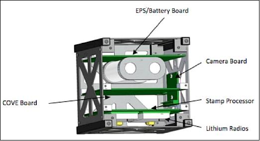
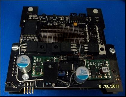
A detailed analysis was performed of the deployment issue leading to manufacture and recommended use of new separation springs designed to minimize potential conjunction issues (note that this was the first time two CubeSats have conjoined after deployment). In addition, since MCubed-2/COVE is manifested to fly on an Atlas-5 with the NPSCul (Naval Postgraduate School CubeSat Launcher) deployment system on the ABC (Aft Bulkhead Carrier), the flight structure has been re-engineered to sustain the increased launch loads. Additional structural improvements have also been added to ease integration of the overall system as seen in Figure 1.
Some additional enhancements were added to the flight system to test MXL (Michigan Exploration Lab) new hardware on a reliable avionics stack including ADCS sensors, algorithms, and a magnetorquer. The team also addressed all of the required items in the Mission Readiness Review related to system, mechanical, and electrical design, and environments. The spacecraft complies with NASA’s end-of-life plans and after the primary mission objectives have been achieved MXL will continue to operate the satellite to continue to assess flight heritage and for educational outreach.
Like its predecessor MCubed, the MCubed-2 CubeSat is composed of in-house, student-developed spacecraft subsystems built from COTS (Commercial Off-The-Shelf) hardware. The spacecraft corresponds to the 1U CubeSat form factor standard in size (10 cm x 10 cm x 10 cm) and mass (≤ 1kg). The main structure is composed of six rectangular isogrid panels attached to four rails at each corner. The isogrid panels provide rigidity while being lower in mass than a solid panel. The rails to which these panels are attached will be hollowed out from the bottom face to reduce mass as well as providing a channel through which the power and electrical subsystem can access the spring-loaded plunger necessary to indicate the release of MCubed-2 from the P-POD (Poly Picosatellite Orbital Deployer).
ACS (Attitude Control Subsystem): MCubed-2 utilizes a passive magnetic attitude control subsystem to achieve a proper orientation for Earth-imaging. The assembly consists of a single permanent magnet aligned on one CubeSat body axis, along with additional magnetic hysteresis materials aligned on each additional perpendicular body axis. In this configuration, the permanent magnet aligns one body axis of the CubeSat with the local Earth magnetic field direction. Since the magnet still permits CubeSat rotation about this single axis, the hysteresis materials are added to dampen unwanted rotation. Chosen for their high magnetic permeability, the HuMy80 hysteresis materials create internal current as they are rotated through the local magnetic field. This dissipates rotational energy as heat, effectively damping the rotational motion of the CubeSat.
In practice, this passive attitude control system will allow for Earth-imaging throughout only a designated portion of the MCubed -2 orbit. Ideally, the camera will continuously point in the nadir direction or straight down towards Earth. Since the camera is aligned along the permanent magnet axis, however, its direction relative to nadir is dictated by the CubeSat’s orbital position. Figure 2 illustrates the shape of the Earth magnetic field lines, as well as the camera orientation at each point in a typical polar orbit.
Although limited in performance, this type of passive control system was chosen for several reasons. When compared with active attitude control systems, such as magnetic torque coils, passive systems of this type require less mass and no power consumption. Furthermore, passive attitude systems offer a robust, simple control strategy that boasts extensive flight heritage in similar Earth-imaging CubeSat missions.
EPS (Electric Power Subsystem): MCubed-2 utilizes solar arrays for power generation which are surface mounted on the outside of the CubeSat. The power collected by the solar cells is sent through current and voltage sensors connected to the microcontroller and then through a 5 V voltage converter, where is it distributed between active buses controlled by switches (during discharge mode) or to the battery charger (during charge mode). When MCubed-2 is in discharge mode, the solar cell power is supplemented by the battery power through either a 3.3 V or 12 V voltage converter to power other buses. The satellite is expected to require 1.2 W of average power and 4.7 W of peak power.
C&DH (Command & Data Handling) subsystem: The C&DH is in charge of all onboard monitoring and control functions. This includes also the control of the payload camera operations and the compression of the imagery.
The Stamp9G20 microcontroller from Taskit is used as OBC. This is a computer on module device, meaning it contains all the vital parts of a computer on a single circuit board. The Stamp9G20 has 400 MHz ARM9 core, 54 MB of SDRAM, 128 MB of NAND Flash, and an extensive set of connectivity ports. Running a real-time Linux operating system, the Stamp9G20 is extensible for future missions. Initial tests show successful operation even in thermal vacuum conditions.
The C&DH subsystem is providing the command interface for the payload interface module, the JPL payload (MSPI OBP algorithm), and the telemetry subsystem. The microcontroller is powered on at all times and is monitored by an external watchdog timer. The system operates at 8 MHz on a 3.3 V bus and can communicate over SPI (Serial Peripheral Interface), I2C (Inter-Integrated Communication), and USART (Universal Synchronous/Asynchronous Receiver Transmitter) protocols. USART is used to communicate with and control the radio transceivers. An I2C bus is implemented to communicate with the payload PXA270 and the EPS health data.
The C&DH subsystem is required to control the camera, and to sample pictures to reject images of space, clouds, or open ocean. Once an acceptable picture is selected, the C&DH subsystem will compress the image for transmission. Additionally, the C&DH subsystem needs to collect system voltage and current health status to transmit to ground.
RF communications: The communication subsystem’s main objective is to transmit the data from onboard MCubed-2 to the ground station. Using a 144 MHz (VHF) uplink and a 430 MHz (UHF) downlink, amateur radio bands will be used to control and receive data from the satellite. A basic beacon signal containing satellite health data will be transmitted intermittently throughout operations. The Li-1 (Lithium-1) radio CubeSat Kit of Astronautical Development LLC, Sunnyvale, CA is used for UHF/VHF communications.
A dedicated receiver will operate at all times, while the dedicated transmitter will be operated only to send a beacon signal or transmit picture data. Both receiver and transmitter are the same component, Analog Devices ADF7020-1, hardwired to their independent tasks to save development time and costs. From the transmitter, the signal will be amplified to 1 W, the calculated necessary transmit power. A 16 cm monopole and a 40 cm monopole are the respective antennas for downlink and uplink. Data and commands will be transmitted using the AX.25 protocol, a standard in amateur radio data transmission.
Launch
The MCubed-2 CubeSat was launched as a secondary payload on Dec. 6, 2013 (7:13:40 UTC) on an Atlas-5-501 vehicle from VAFB, CA. The primary payload on this flight was the classified NROL-39 reconnaissance mission of NRO (National Reconnaissance Office). The launch provider was ULA (United Launch Alliance). 4) 5) 6) 7)
Note: The NROL-39 is reported to be a Topaz radar-imaging reconnaissance satellite with the FIA Radar-3 payload of the cancelled FIA (Future Imaging Architecture) program. FIA was a program to design a new generation of optical and radar imaging US reconnaissance satellites for NRO. Despite the optical component's cancellation in 2005, the radar component, with a code name of Topaz,has continued, with two satellites in orbit as of November 2013; these are: NROL-41, launched on Sept. 21, 2010, and NROL-25, with a launch on April 03, 2012. A total of 5 radar satellites are in the Topaz program (Ref. 5). 8)
Secondary Payloads
Next to the NROL-39 primary payload, the Atlas-5 hosts the GEMSat/ELaNa-2 mission for the NRO and the NASA/LSP ( Launch Services Program), lifting 12 CubeSats/nanosatellites to orbit as secondary payloads. All 12 CubeSats/nanosatellites are considered to be technology missions. 9) 10)
• AeroCube-5a and -5b, two 1.5U CubeSats of The Aerospace Corporation.
• ALICE (AFIT LEO iMESA CNT Experiment), a 3U CubeSat of AFIT (Air Force Institute of Technology)
• CUNYSAT-1 (City University of New York-1), a 1U CubeSat of Medgar Evers College, Brooklyn, N.Y. of the City University of New York.
• FIREBIRD-A and -B (Focused Investigations of Relativistic Electron Burst, Intensity, Range and Dynamics), two 1.5U CubeSats of Montana State University, University of New Hampshire, Los Alamos National Laboratory, and The Aerospace Corporation.
• IPEX, also known as CP8, is a 1U CubeSat of Cal Poly (California Polytechnic State University) and NASA
• MCubed-2/COVE, a 1U CubeSat of the University of Michigan, Ann Arbor, MI and of NASA/JPL
• SMDC-ONE-2.3 (Charlie) and SMDC-ONE-2.4 (David), two 3U CubeSats of the U.S. Army SMDC/ARSTRAT (Space & Missile Defense Command/Army Forces Strategic Command) of Huntsville, AL (Redstone Arsenal)
• SNaP (SMDC NAnosatellite Program), a 3U CubeSat of the U.S. Army SMDC/ARSTRAT
• TacSat-6 (Tactical Satellite-6), a 3U CubeSat of the U.S. Army SMDC/ARSTRAT. TacSat-6 will be operated in conjunction with the ORS (Operationally Responsive Space) Office; it forms part of the TacSat program of technological research satellites.
The CubeSats are integrated into 8 P-PODs (Poly-Pico Orbital Deployers ), which are contained in the NPSCuL (Naval Postgraduate School CubeSat Launcher), built by NPS students of Monterey, CA. The NPSCuL, together with the 8 P-PODs and 12 CubeSats, is referred to as GEMSat (Government Experimental Multi-Satellite), and is attached to the Centaur upper stage's ABC (Aft Bulkhead Carrier), Figure 8. The assembled GEMSat is shown in Figure # ready for mate to the launch vehicle along with the members of the various institutions from NPS, OSL (Office of Space Launch), ULA (United Launch Alliance) and Cal Poly. 11)
Orbit: The primary payload was launched into a sun-synchronous near-circular orbit, altitude of ~1075 km x 1089 km, inclination of 123º (deployment ~07:32 UTC).
• The Centaur AV-042 upper stage then made two orbit lowering burns to a SSO of 467 km x 883 km at an inclination of ~120.5º. Attached to the AV-042 was GEMSAT, the second NPSCuL CubeSat launcher, which ejected 12 CubeSats between around 10:22 and 10:38 UTC. 12)
Mission Status
• April 22, 2014 operational status: MCubed-2 continues to be successfully tasked to operate COVE and perform experiments. The project recently ran the 25th successful COVE run on pic6, a picture taken by MC2 on 09 February 2014 over northern Michigan. A successful run means that the COVE payload processed the image, and that the data produced by the algorithm matched the data produced during the first COVE run on pic6, which was verified by the ground test unit at JPL (Jet Propulsion Laboratory). 13)
• Feb. 10, 2014: The MCubed-2 (MC2) team at MXL (Michigan Exploration Laboratory) successfully captured the first image of Earth. Figure 9 is a snow-covered picture of Lake Superior, the upper peninsula of Michigan, Wisconsin, Minnesota, and Canada. The deep freeze of the Midwest is clearly visible. 14)
• Dec. 13, 2013: The CubeSat On-board Processing Validation Experiment (COVE) aboard MCubed-2 has successfully run and completed its first task without any issues! COVE utilizes an advanced radiation-hardened FPGA processor and image processing algorithms that will be used for high-data-rate processing in future Earth science missions. 15)
• Dec. 9, 2013: The ops team successfully command MC2 (MCUbed-2) this morning! This is a major hurdle for the team as on MC1, uplink was unsuccessful due to a variety of factors. The team is now readying commands to assess the status of the payload, COVE, and download further telemetry from the satellite. 16)
• Dec. 8, 2013: MCubed-2 beacons continue to show good health. The project is currently tuning up the MXL ground stations to maximize SNR. The project is now attempting to establish uplinks. 17)
• On December 6, 2013, first beacons were received shortly after launch from global HAMS and MCubed-2 appears healthy.
Sensor Complement
Camera
The primary payload of MCubed-2 is an OmniVision 2 Mpixel CMOS camera chip (OV2655) that will take quality color images of the Earth from LEO (Low Earth Orbit) at a resolution of < 200 m. This requires a data transfer of 1600 x 1200 pixels (3.76 MB/image) from the camera to the MCubed-2 flight computer using the I2C (Inter -Integrated Circuit) and ISI (Image Sensor Interface) protocols.
The CMOS color camera with a 9.6 mm EFL (Effective Focal Length) Plano-convex lens (Figure 10). The camera will take an image and save it to a Colibri PXA270 microprocessor at a resolution of 1280 x 1024 pixels, each pixel with a size of 3.6 µm x 3.6 µm. This allows for moderate to high-resolution images of the Earth after postprocessing. Even with the lens positioned at the correct focal length, the whole camera payload subsystem is fairly small and takes up only 55 cm3 of volume (Ref. 22). The CMOS camera is also referred to as µEye.
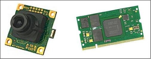
The MCubed-2 project selected the Stamp9G20 microprocessor of Taskit GmbH, Berlin, Germany to save and process the imagery.
The Stamp9G20 is a small and compact CPU module. All components, such as the processor or the memory unit, are integrated onto a board measuring just 53 mm x 38 mm x 6 mm. It was conceived for industrial applications and is well-suited as a basis for developing mobile devices and embedded computing solutions. Typical application domains for the Stamp9G20 include, for example, data logging, log conversion or measurement systems of all types.
Stamp9G20 comes with the Linux open-source operating system and the U-Boot boot loader pre-installed. Linux offers all the functionalities of a modern operating system. Multitasking, virtual memory management and dynamically loaded libraries make Linux ideal for many fields of application.
COVE (CubeSat On-board processing Validation Experiment)
COVE is a NASA/JPL (Jet Propulsion Laboratory) payload with the goal to advance the TRL (Technology Readiness Level) of the new Virtex-5 SIRF device implemented with the MSPI (Multiangle SpectroPolarimetric Imager) OBP (On-Board Processing) algorithm.
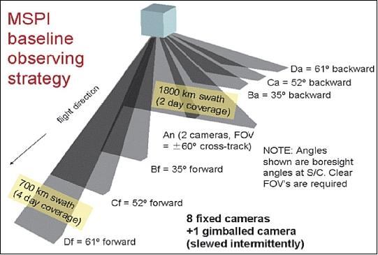
COVE is a payload experiment that will prove an image processing algorithm designed for the MSPI (Multiangle Spectropolarimetric Imager) utilizing the first in-space application of a new radiation-hardened-by-design Virtex-5QV FPGA by Xilinx. This experiment will advance the technology required for the future spaceborne implementation of the MSPI instrument required for real-time high data rate instrument processing relevant to future Earth observing missions. MSPI is a multiangle multiwavelength highly accurate polarization camera that will characterize aerosols contributing to an understanding of their effects on cloud formation, and other phenomena. Limited understanding of the complex interactions among clouds and aerosols is one of the largest contributors to uncertainty in climate models. - MSPI is a payload on the Decadal Survey ACE (Aerosol-Clouds and Ecosystems) mission, planned for launch in the timeframe 2020, and the OBP (On-Board Processor) of MSPI is to calculate the polarimetry data as imaged by each of the 9 cameras forming the instrument. 18) 19) 20) 21) 22) 23) 24) 25)
The MSPI requirements for the ACE mission call for:
• The measurement of cloud and aerosol properties via 9 cameras
• Each camera processes 95 MB/s of raw video data that must be reduced by two-orders of magnitude for spaceborne deployment
• To be achieved via instrument signal processing not compression.
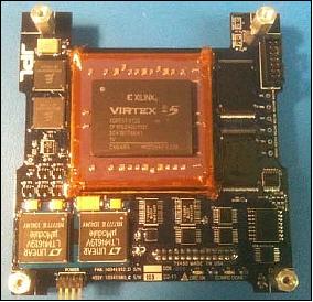
The COVE board is designed to allow for image data to be transferred to shared on-board memory without turning on the FPGA (the most power-consuming device on the board). The FPGA is only powered on when necessary to process already acquired image data; however, a direct data transfer mode does exist for circumstances when it is desirable to extend the FPGA’s operation in the space environment (after primary mission objectives have been met). Nominally, the FPGA will be powered on only long enough to process the image data and transfer its results.
In order to fit comfortably inside the MCubed-2 satellite frame, the COVE board was designed to measure 90 mm x 90 mm. The footprint of the FPGA alone is 42.5 mm x 42.5 mm. The remaining board space had to accommodate memory, configuration PROMs (Programmable Read-Only Memory), regulators, ADCs (Analog-to-Digital Converters) and other support components.
Power interface: MCubed-2 provides raw battery voltage in the range of 6.0-8.4 V to the COVE payload. The COVE board regulates secondary voltages required for all of its components, as indicated below:
• FPGA: 3.3 V, 2.5 V, 1.0 V
• Configuration PROM: 3.3 V, 1.8 V
• Magnetoresistive RAM: 3.3 V
• Flash memory: 3.3 V
• ADCs: 3.3 V, 1.25 V
• Buffers, muxes: 3.3 V.
MCubed-2 additionally made available to COVE 3.3 V and 5 V regulated power with current limits of 2 A on each line. While the COVE design for MSPI OBP could work with this dual input power supply interface (as demonstrated in the EM design), there were two reasons why the project elected to use the single unregulated power bus input for the final FM (Flight Model) design.
- The first reason is that by not limiting the input power to 2 A, future FPGA designs that consume more power than the MSPI OBP design can be accommodated (via upload reconfiguration).
- Secondly, also to accommodate future COVE payload applications, interface requirements are eased and testing is simplified by requiring only a single supply input of a wide voltage range (the project selected dc-dc power converters that can run off any input voltage in the range of 5.5 V to 26.5 V).
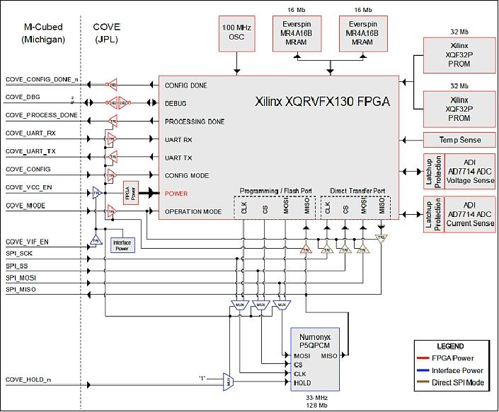
The COVE payload architecture, presented in Figure 14, can be subdivided into the following logical subsystems:
• FPGA, PROMs, clock resources
• Shared memory
• Non-shared memory
• System health measurement
• Power
• Isolation buffers.
Unlike the commercial-grade Virtex-5 FPGA, the V5QV does not have an embedded PowerPC processor. The MSPI OBP algorithm requires the use of a processor which supervises and controls the algorithm running in the FPGA fabric. On the V5QV, the project utilizes the MicroBlaze soft-core processor to replace the PowerPC.
Since the V5QV is an SRAM-based volatile FPGA, it requires non-volatile configuration PROMs in order to load a bitstream on power-on. The project uses two extended temperature range XQF32P PROMs to store one FPGA configuration bitstream. These PROMs are reprogrammable via a JTAG interface, accessible on the ground only. Before final integration with MCubed-2, the project programs these PROMs with the latest FPGA firmware and MicroBlaze software.
Only a single clock source is required on the COVE board. The project uses a 100 MHz oscillator to provide the main system clock for the FPGA. Internally in the FPGA, PLL (Phase Lock Loop) and DCM (Digital Clock Manager) blocks perform all the necessary clock distribution.
Shared memory: The primary method of transferring image data to the FPGA and processed results to the MCubed-2 is via a shared flash memory device. A secondary data transfer mechanism exists via an SPI bus transfer directly from MCubed-2 to FPGA. In this mode, the FPGA must stay powered on the the data transfer (and subsequent image processing). The Numonyx P5QPCM flash is accessible via an SPI bus. On the COVE board, the flash SPI bus is multiplexed between the FPGA and MCubed-2, allowing either device to have independent access to the shared memory. When accessed by MCubed-2, the FPGA can be powered off.
Non-shard memory: The COVE board is also populated with non-volatile MRAM (Magnetoresistive Random Access Memory), intended for use as additional instruction and data storage for the MicroBlaze processor and FPGA. Although the OBP algorithm fits entirely within on-chip FPGA memory (BRAM) having additional external RAM enables future memory-demanding designs to be uploaded to the COVE board.
System health measurement: Two Analog Devices AD7714 ADCs and a Maxim MAX6627 temperature sensor measure board voltage, current, and operating temperature of the FPGA. All three devices operate over independent SPI buses tied directly to the FPGA. Data from the ADCs and the temperature sensor is recorded by the FPGA and reported to MCubed-2 along with the image processing results.
Communication interface: COVE communicates with MCubed-2 over a 26-pin ribbon cable that is shared with other CubeSat subsystems. Out of a total of 26 I/O lines, 15 are allocated for communication with COVE.
Power: Two Linear Technology LTM4619 dual 4-amp DC/DC converters are supplied by the unregulated MCubed-2 battery voltage and output 3.3 V (VIF), 3.3 V (VCC), 2.5 V, and 1.0 V secondary voltages. A single Linear Technology LT3029 dual low-dropout (LDO) regulator generates the remaining low-current secondary voltages by first regulating the 2.5 V rail down to 1.8 V and then 1.8 V down to 1.25 V. Enable pins on these parts are used to switch power on/off eliminating the bulky MOSFET based switching circuits used on the EM board. Secondary supply currents are monitored with Maxim MAX9634 current-sense amplifiers driving the ADC.
Isolation buffers: Since the FPGA on the COVE board is not powered on at all times, special care must be taken not to exercise I/O lines tied to the FPGA while it is in the off state. We utilize tri-state buffers and inverters to isolate the FPGA from MCubed-2 and other board components that may be in a powered state when the FPGA is off. Additionally, these buffers are capable of the bus-holdiv functionality, ensuring that all I/O to other devices on the COVE board is held at a non-floating logic level.
COVE concept of operations: The COVE board is designed with the intent to minimize power consumption while offering the full data processing capability of the V5QV FPGA. This is achieved by selectively powering on/off the interface and the FPGA. In the section below, parentheses indicate the specific component in the MCubed-2/COVE design, but can be generalized for other CubeSat applications.
COVE primary mission: During most of MCubed-2 operation, the COVE board is powered off. Although the voltage regulators receive power from the battery, their control lines are set to disable voltage output.
When MCubed-2 has acquired an image (taken with its on-board OmniVision camera) and is ready for onboard processing, a command is sent to COVE to turn on its SPI interface and flash memory. MCubed-2 then writes the raw image data to a predetermined address in the shared flash memory. This process can take nearly 3 minutes for a standard 5.76 MB image because the (Stamp9G20) microprocessor on MCubed-2 is limited in its SPI transfer rates to approximately 30 seconds per MB. The power consumption in this step, however, is very low (~0.25 W) as only a few devices on the COVE board are in the on state.
Once the full image has been transferred to the shared flash memory, the (Stamp9G20) microprocessor gives up control of the shared flash memory and commands COVE to turn on the FPGA. The V5QV FPGA loads the configuration bitstream from the PROMs and begins to read and process the data from the shared flash memory. The results of the (MSPI algorithm) data processing are written back to the shared flash memory into a predefined address space.
The FPGA notifies the (Stamp9G20) microcontroller when it is done processing data. The microcontroller then acquires control of the shared flash memory and commands the FPGA to power off. The processed data is then read back by the (Stamp9G20) microcontroller and the COVE payload activity is complete. As the final step, the microcontroller commands the COVE payload to power off its SPI interface and flash memory.
Future use of COVE: Once the primary mission is complete, the COVE board could be made available to other customers to demonstrate their FPGA-based technology on the V5QV FPGA. To accommodate future uses of the COVE payload, the board is designed with the ability to upload new configurations to the FPGA while MCubed-2 is on orbit. In addition to the XQF32P PROMs that store the “golden” bitstream (non-updateable on orbit), the FPGA is also able to configure from the shared flash memory. A region of the shared flash memory is reserved for storing a secondary configuration bitstream. This bitstream may be uploaded to the flash memory from the microcontroller in the same manner image data is transferred to this memory.
COVE also provides non-volatile MRAMs for external code and data storage as may be required by future memory intensive MicroBlaze applications. This use case is enabled by first uploading a new configuration bitstream into the shared flash memory, including additional content for insertion into the MRAMs. Upon configuration, the FPGA can be instructed to copy certain contents of the shared flash memory into the MRAMs and then commence MicroBlaze processor boot.
References
1) Charles D. Norton, Steve A. Chien, Paula J. Pingree, David M. Rider, John Bellardo, James W. Cutler, Michael P. Pasciuto, “NASA’s Earth Science Technology Office CubeSats for Technology Maturation,” Proceedings of the 27th AIAA/USU Conference, Small Satellite Constellations, Logan, Utah, USA, Aug. 10-15, 2013, paper: SSC13-XI-4, URL of paper : http://digitalcommons.usu.edu/cgi/viewcontent.cgi?article=2987&context=smallsat
2) Paula J. Pingree, “Looking Up: The MCubed/COVE Mission,” Proceedings of the 11th Annual CubeSat Developers’ Workshop - The Edge of Exploration,” San Luis Obispo, CA, USA, April 23-25, 2014, URL: http://www.cubesat.org/images/.../DevelopersWorkshop2014/Pingree_MCubed_COVE_Mission.pdf
3) “M-Cubed2,” MXL, URL: https://web.archive.org/web/20160805182212/http://exploration.engin.umich.edu/blog/?page_id=1830
4) http://en.wikipedia.org/wiki/2013_in_spaceflight#December
5) William Graham, “Atlas V launches NROL-39 from Vandenberg,” NASA Spaceflight.com, Dec. 5, 2013, URL: http://www.nasaspaceflight.com/2013/12/atlas-v-launch-nrol-39-vandenberg/
6) Stephen Clark, “Government spy satellite rockets into space on Atlas 5,” Spaceflight Now, Dec. 6, 2013, URL: http://www.spaceflightnow.com/atlas/av042/131206launch/#.UqHYgCeFdm4
7) NROL-39, United Launch Alliance Atlas V Rocket Successfully Launches Payload for the National Reconnaissance Office,” ULA, Dec. 6, 2013, URL: https://web.archive.org/web/20180114080208/http://www.ulalaunch.com:80/site/pages/News.shtml
8) “Future Imagery Architecture,” Wikipedia, URL: http://en.wikipedia.org/wiki/Future_Imagery_Architecture
9) Patrick Blau, Atlas V to launch with classified NROL-39 & 12 CubeSats in December, Nov. 15, 2013, URL: http://www.spaceflight101.com/atlas-v-nrol-39-launch-updates.html
10) Bryan Klofas, “Upcoming CubeSat Launches: The Flood Has Arrived,” AMSAT-NA Symposium Houston, TX, USA, 1 November 2013, URL: http://www.klofas.com/papers/klofas_amsat2013.pdf
11) “Atlas V GEMSat Launch 2013,” URL: http://www.cubesat.org/index.php/missions/upcoming-launches/134-l39-launch-alert
12) Jonathan's Space Report No. 690, Dec 6, 2013, URL: https://planet4589.org/space/jsr/back/news.690.txt
13) “MCubed-2 Operations, Telemetry and Tracking,” MXL, April 22, 2014, URL: http://exploration.engin.umich.edu/blog/?page_id=1933
14) “MC2 Confirms Michigan is Snow-Covered!,” MXL, Feb. 10, 2014, URL: http://exploration.engin.umich.edu/blog/?p=2078
15) Logan Sisca, “COVE Autorun Success,” MXL (Michigan Exploration Laboratory), Dec. 13. 2013, URL: http://exploration.engin.umich.edu/blog/?cat=27
16) “MC2 uplink successful!,” UMich, Dec. 9, 2013, URL: http://exploration.engin.umich.edu/blog/?cat=27
17) “MCubed-2 Operations, Telemetry and Tracking,” University of Michigan, Update Dec. 13, 2013, URL: https://web.archive.org/web/20160805181629/http://exploration.engin.umich.edu/blog/?page_id=1933
18) Paula J. Pingree, “Technology Readiness Level (TRL) Advancement of the MSPI On-Board Processing Platform for the ACE Decadal Survey Mission,” ESTF 2011 (Earth Science Technology Forum 2011), Pasadena, CA, USA, June 21-23, 2011, URL: http://esto.nasa.gov/conferences/estf2011/papers/Pingree_ESTF2011.pdf
19) Paula J. Pingree, Dmitriy L. Bekker, Thomas A. Werne, Thor O. Wilson, “The Prototype Development Phase of the CubeSat On-Board Processing Validation Experiment,” 2011 IEEE Aerospace Conference, Big Sky, MT, USA, March 5-12, 2011, paper: 2.0402
20) Thomas A. Werne, Dmitriy L. Bekker, Paula J. Pingree, “Real-Time Data Processing for an Advanced Imaging System Using the Xilinx Virtex-5 FPGA,” Proceedings of the 2010 IEEE Aerospace Conference, Big Sky, MT, USA, March 6-13, 2010
21) Paula J. Pingree, “Real-Time On-Board Processing Validation of MSPI Ground Camera Images,” ESTF (Earth Science Technology Forum) Arlington, VA, UAS, June 22- 24, 2010, URL: http://esto.nasa.gov/conferences/estf2010/presentations/Pingree_ESTF2010_a4P3.pdf
22) Dmitriy L. Bekker, Thomas A. Werne, Thor O. Wilson, Paula J. Pingree, Kiril Dontchev, Michael Heywood, Rafael Ramos, Brad Freyberg, Fernando Saca, Brian Gilchrist, Alec Gallimore, James Cutler, “A CubeSat Design to Validate the Virtex-5 FPGA for Spaceborne Image Processing,” Proceedings of the 2010 IEEE Aerospace Conference, Big Sky, MT, USA, March 6-13, 2010
23) Dmitriy L. Bekker, Paula J.Pingree, Thomas A. Werne, Thor O. Wilson, Brian R. Franklin, “The COVE Payload – A Reconfigurable FPGA-Based Processor for CubeSats,” Proceedings of the 25th Annual AIAA/USU Conference on Small Satellites, Logan, UT, USA, Aug. 8-11, 2011, paper: SSC11-I-2
24) “NASA Launches JPL-Built Earth Science Experiment,” Space Daily, Nov. 2, 2011, URL: http://www.spacedaily.com/reports/NASA_Launches_JPL_Built_Earth_Science_Experiment_999.html
25) Charles D. Norton, Michael P. Pasciuto, Paula Pingree, Steve Chien, David Rider, “Spaceborne flight validation of NASA ESTO technologies,” Proceedings of IGARSS (International Geoscience and Remote Sensing Symposium), Munich, Germany, July 22-27, 2012
The information compiled and edited in this article was provided by Herbert J. Kramer from his documentation of: ”Observation of the Earth and Its Environment: Survey of Missions and Sensors” (Springer Verlag) as well as many other sources after the publication of the 4th edition in 2002. - Comments and corrections to this article are always welcome for further updates (eoportal@symbios.space).