Max Valier Sat
EO
Operational (nominal)
Imaging microwave radars
AIS
Quick facts
Overview
| Mission type | EO |
| Agency | TFOBZ |
| Mission status | Operational (nominal) |
| Launch date | 23 Jun 2017 |
| Instruments | AIS, GPS receiver |
| Instrument type | Imaging microwave radars |
| CEOS EO Handbook | See Max Valier Sat summary |
Max Valier Sat
Spacecraft Launch Sensor Complement References
The Max Valier nanosatellite project was initiated in the fall of 2007 at the Max Valier technical high school GOB (Gewerbeoberschule Bozen, Bolzano), South Tyrol, Italy. At the time, Manfred Fuchs, the CEO (Chief Executive Officer) of the OHB-System AG of Bremen (Germany), was visiting his former high school in Bozen. The topic was quickly on satellites and Manfred Fuchs promised to help his school in the development of their own space project. The nanosatellite project started actually in the spring of 2008. 1) 2) 3)
The Max Valier nanosatellite project presents a unique collaboration of educational institutions, industry, and research facilities for the realization of a <16 kg nanosatellite with a multiple sensor complement. The nearby "Oskar von Miller" GOM (Gewerbeoberschule Meran), South Tyrol, Italy, joined the project of GOB, so did the amateur astronomers of the Max Valier public observatory near Bozen.
The excellent contacts of Manfred Fuchs in the European space arena resulted in collaborations of OHB with MPE Garching, DLR in Oberpfaffenhofen, and the Fraunhofer Institute Euskirchen, Germany. Peter Predehl of MPE suggested to fly a miniaturized X-ray telescope as payload for the satellite and promised its delivery in line with the project schedule, as well as support for the data reduction, which has to be done by the Max Valier amateur astronomers.
Additional payloads are: a GPS receiver of DLR, a CMOS camera, and an AIS receiver.
The primary objective of the mission is to engage the students and teachers in the various aspects of this space adventure with hands-on experience. It implies a step forward in education for all parties involved.
Background: Max Valier (1895-1930) was born and raised in Bozen (Bolzano, Italy) and studied in Innsbruck. After WW-I, he became a science-fiction writer and an amateur astronomer. In the 1920s, Max Valier was fascinated by Hermann Oberth's book: "Die Rakete zu den Planetenräumen" (The Rocket to Planetary Space). In 1924, Max Valier and Hermann Oberth published a book: "Der Vorstoss in den Weltenraum" (The Drive into Space), which contained a visionary description of a rocket program. In 1927, Max Valier proposed a rocket-powered aircraft. As one of the first pioneers of rocketry, Max Valier was killed in a test firing of a rocket engine on May 17, 1930 in Berlin. The history of space flight is also the history of the rocket. Only a rocket is able to overcome Earth's gravity and to travel into space. - The GOB in Bozen and the Public Observatory of Bozen are honored to carry the name of the native pioneer Max Valier.
Spacecraft
The nanosatellite is being designed, developed and integrated mainly by both high schools with support and mentoring of OHB engineers. Both technical high schools have considerable qualifications and experience in microcontroller, PCB-design, power electronics, telecommunication systems, mechanics and information systems.
The spacecraft bus consists of a fairly flat aluminum box (3 mm wall) of size: 250 mm x 250 mm x 80 mm. Several internal cable tunnels and bridges provide the required stiffness and stability of the bus structure. The satellite has a passive thermal subsystem. The mass of the bus is 3.8 kg, the design life is 1 year.
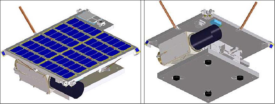
The most visible feature is a top panel (Figure 1 left) carrying six strings of solar cells and a set of dipole and patch antennas. In addition, it carries a fine sun sensor (its square shaped case is visible in Figure 1, left)above a green momentum wheel with cylindrical shape) and two coarse sun sensors, made up of three square solar cells each (visible in Figure 1, right) in the corners on the front and back side). Below the top panel there is a stack of aluminum cassettes to house Radio Frequency transmitters and receivers, two single board computers and several printed circuit boards carrying the electronics needed to interface the computers with the peripheral hardware. Next to the aluminum cassettes the X-Ray detector is clearly visible in Figure 1 (right) on the left side, while on the right side a momentum wheel needed for attitude control also helps to make the mass distribution symmetrical.
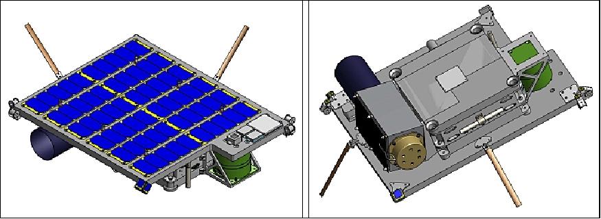
The z-axis of the body coordinate system is normal to the top panel, pointing upwards from the solar cells. The y-axis is parallel to the X-Ray detector's symmetry axis, and the x-axis completes a right-handed system.
One side of the top panel is about 50 cm in length, the total mass of the satellite is about 16 kg. According to present planning, Max Valier's orbit will be circular and have an inclination of 98º, an altitude of 600 km and it will be sun synchronous with an LTAN at 17:00 hours.
ACS (Attitude Control Subsystem): The satellite is 3-axis stabilized (momentum biased) using magnetic torquers and a small reaction wheel, mounted normal to the solar generator surface. Attitude sensing is based on a combination of sun- and magnetic field vector measurements , consisting of CSS (Coarse Sun Sensor) FSS (Fine Sun Sensor), MM (Magnetometer), and STC (Star Camera). 4)
The CSS is made up of six triple junction solar cells with a surface of 2 cm2 each and a short circuit current of 34 mA. The FSS is a four quadrant photodiode detector with an angle resolution of up to 0.03º and a nominal FOV (Field of View) of 128º x 128º. The magnetic field sensor is a three axis magnetoresistive sensor with a resolution of 100 pT and a field range of 64 µT. The STC is supplied by ÄAC Microtec (Uppsala, Sweden) and will be used for a posteriori attitude determination to match X-ray data with inertial coordinates.
Actuation is provided with three MTs (Magnetic Torquers) with a nominal magnetic moment of 1 Am2 and one MW (Momentum Wheel). The torquers are supplied by ZARM Technik, while the MT with a nominal angular momentum of 0.125 Nms at 4000 rpm is supplied by Satellite Services.
The X-ray telescope requires (a posteriori) attitude determination with an accuracy of at least 0.5º in order to reconstruct the pointing vector of the X-ray telescope. This accuracy is achieved by using the measurements of a fine sun sensor (measuring in 2 axis) and a 3-axes magnetometer. The sun direction corresponds to the scan plane normal, the magnetic field vector indicates the scan phase (angle). An on-board orbit propagation function is providing the orbital sub-satellite location, needed for the evaluation of the magnetic field measurement.
Since the momentum wheel axis is arranged perpendicular to the solar generator plane, the angular momentum stored in the wheel is always on the generator plane normal. To direct this axis to the sun (and to maintain this direction) the 3 magnetic torquers are applied. The angular movement around this axis (i.e. the scan phase) is controlled by the reaction wheel speed variation.
Operational modes of the ACS:
- Momentum biased stabilization with nominally two scan rotations per orbit while maintaining the solar array sun pointed (the rotation speed can be adjusted).
- Nadir optimized pointing with one scan per orbit, the momentum vector (and solar array) are being pointed towards the sun
- Fixed scan angle with the solar array pointed towards sun. This mode allows prolonged pointing and exposure time for the X-ray telescope.
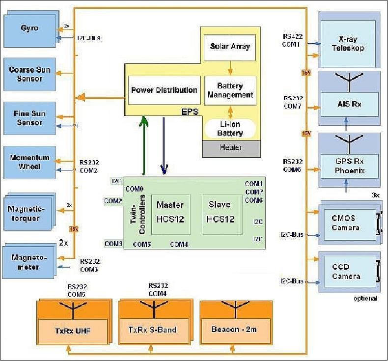
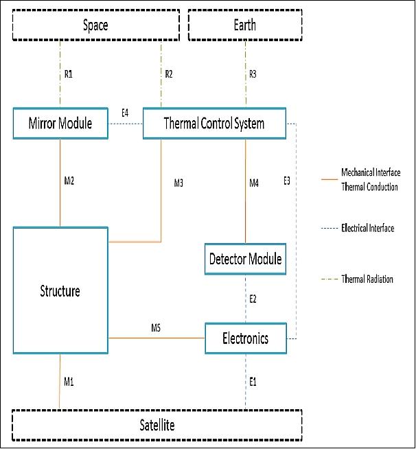
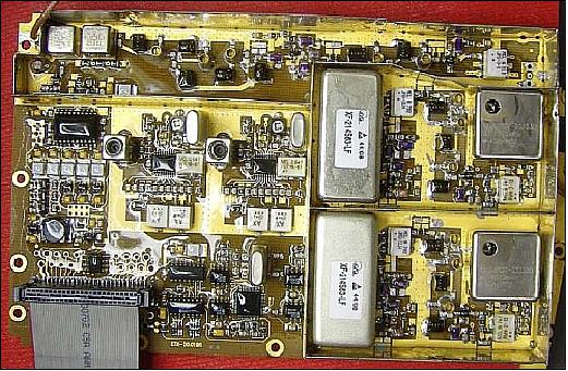
OBDH (On-Board Data Handling) subsystem: The OBDH is based on a Arm7 microcontroller configuration on a Quake board. The OBDH is providing its services to all ADCS and EPS functions and collects the payload data. In addition, an HCS12 microcontroller is used for on-board communications. The I2C bus is being used for on-board communications along with point-to-point connections (RS422, RS232) as shown in Figure 2.
EPS (Electrical Power Subsystem): The EPS features a surface-mounted non-deployable sun pointing solar array covering the top side of the spacecraft (Figure 1). An average power of ~10 W is generated by the solar generator from Clyde Space, UK. The solar panels are arranged in 4 parallel strings with 9 cells to each string. The solar current charges 4 Li-ion batteries (capacity of 2.3 Ah) provided by ABSL, UK. The on-board power is distributed at 14-16.4 V. In addition, DC power is distributed at 10 V, 5 V and at 3.3 V.
RF communications: An on-board data storage capacity of 4 GByte is provided. The primary link is the amateur band in VHF/UHF with downlink and uplink data rates of 9.6 kbit/s. In addition, a bi-directional S-band link (2.4 GHz) provides downlink data rates of up to 500 kbit/s (AIS data and/or imagery). In addition, an amateur radio beacon is available. The ground control stations in Bozen and Meran will be used to operate the satellite. An additional ground station is provided at OHB in Bremen.
Launch
The Max Valier nanosatellite was launched on June 23, 2017 (03:59 UTC) as a secondary payload on the PSLV-C38 vehicle in XL configuration of ISRO from SDSC (Satish Dhawan Space Center), India. The primary payload on this flight was CartoSat-2E (~712 kg), the sixth satellite in the Cartosat-2 series (total launch mass of ~955 kg). 5) 6)
All 31 Satellites separated successfully. 7)
Orbit: Sun-synchronous near-circular orbit, altitude of 505 km, inclination = 97.8º, LTDN (Local Time on Descending Node) at 9:30 hours.
Secondary Payloads
• NIUSAT (Noorul Islam University Satellite), located in Kumarakovil, Thuckalay, Kanyakumari District Tamil Nadu, India. NIUSAT is an Earth observation nanosatellite (15 kg). NIUSAT features a RGP camera with a ground resolution of 25 m and a frame size of 50 km x 50 km.
• CE-SAT-1 (Canon Electric Satellite-1), a microsatellite (50 kg) of Canon Electronics Space Technology Laboratory, Japan. The microsatellite features an optical imaging system based on a 40 cm diameter Cassegrain telescope.
• Max Valier, a nanosatellite (16 kg) of the "Max Valier" school Bolzano and the "Oskar von Miller" school Merano, in South Tyrol, Italy.
• D-SAT (Deorbit Satellite), a 3U CubeSat mission (3.5 kg) by the Italian company D-Orbit to demonstrate active end-of-life reentry.
• 3 Diamond nanosatellites (Blue, Green, Red) of Sky and Space Global, UK, developed by GomSpace ApS of Denmark. The three 3U CubeSats (each 6 kg) are pathfinders for Sky and Space Global's 200 Satellite LEO constellation.
• Pegasus, a nanosatellite (2U CubeSat) of FH Wiener Neustadt, Austria (thermosphere research). Pegasus is a member of the QB50 constellation with the m-NLP payload.
• InflateSail, a 3U CubeSat of SSC (Surrey Space Centre) at the University of Surrey, UK (technology demonstration nanosatellite). Part of the QB50 constellation.
• UCLSat (University College London Satellite), a 2U CubeSat of UCL with the INMS (Ion and Neutral Mass Spectrometer), ionosphere research. UCLSat is part of the QB50 constellation.
• NUDTSat (National University of Defense Technology Satellite), Belgium, a 2U CubeSat of NUDT for ionosphere research. NUDTSat features a FIPEX instrument of the QB50 constellation.
• COMPASS-2 (DragSail CubeSat), a 3U CubeSat of FH Aachen, Germany (technology demonstration nanosatellite). COMPASS-2 is part of the QB50 constellation.
• LituanicaSAT-2, a 3U CubeSat of Vilnius University, Lithuania. The CubeSat is part of the QB50 constellation with a FIPEX payload.
• URSA MAIOR (University of Rome la SApienza MicroAttitude In ORbit testing), a 3U CubeSat to study the lower thermosphere. USRA MAIOR is a member of the QB50 constellation with the m-NLP payload.
• VZLUSat-1, a 2U CubeSat Czech technology nanosatellite of VTLU, developed in cooperation with Czech companies (RITE, HVP Plasma, 5M, TTS, IST) and universities (CVUT, University of West Bohemia). The nanosatellite carries on board the following experiments: a miniaturized X-ray telescope, composite material for radiation shielding, FIPEX, a QB50 instrument, to measure the concentration of oxygen in the thermosphere.
• SUCHAI-1 (Satellite of the University of Chile for Aerospace Investigation), a 1U CubeSat (1 kg).
• Venta-1, a nanosatellite (7.5 kg) of Ventspils University, Latvia, developed by Ventspils University College in cooperation with Ventspils High Technology Park, Bremen University of Applied Sciences and OHB Systems.
• Aalto-1, a Finnish student nanosatellite (3U CubeSat) of Aalto University, Aalto, Finland.
• ROBUSTA-1B (Radiation on Bipolar Test for University Satellite Application), a nanosatellite with a scientific experiment developed by the University of Montpellier students (France), a successor to the ROBUSTA satellite, which was launched in February 2012.
• skCube, a 1U CubeSat for educational and popularization outreach developed by SOSA (Slovak Organization for Space Activities ) at the University of Zilina. It is Slovakia's first satellite.
• CICERO-6 (Community Initiative for Cellular Earth Remote Observation-6), a 6U CubeSat of GeoOptics Inc. (~10 kg), Pasadena, CA, built by Tyvak Nanosatellite Systems. The objective is to demonstrate radio occultation observations for a commercial customer. CICERO-6 features Cion (CICERO Instrument for GPS-RO) with a mass of 1.2 kg. Cion has a size of 30 x 10 x 6 cm, power of 8 W. 8)
• Tyvak-53b, a technology demonstrator by Tyvak Nanosatellite Systems, Inc. (Irvine, CA) for deorbiting of nanosatellites.
• Lemur-2 x 8. Lemur-2 is commercial satellite constellation of Spire Global Inc., San Francisco, CA, The objective of the Lemur-2 constellation is ship tracking via AIS (Automatic Identification System).
Sensor Complement
µROSI (Micro Roentgen Satellite Instrument)
µROSI, a miniature X-ray telescope for astronomical observations, is the primary instrument on board the spacecraft designed and developed at MPE (Max Planck Institute for Extraterrestrial Physics), Garching, Germany. The objective is to perform an all-sky survey in the soft X-ray bandwidth searching the whole sky for bright X-ray sources with an angular resolution of 1º (the goal is the detection of at least 100 bright sources in the soft X-ray bandwidth). The X-ray data will be evaluated by students of the participating South Tyrolean schools GOB and GOM. This unique project allows us to develop the first X-ray telescope for a small satellite mission opening up a new bandwidth for amateur astronomers. 9) 10) 11)
Miniaturizing an X-ray telescope is a major challenge. Mass restrictions impose strict limits on the size of the telescope. Thus, the biggest challenge for the µROSI project is to define scientific objectives that are achievable with a small telescope and that are meaningful. Given that small telescopes lack the effective area required for high spatial resolution, µROSI is designed for high spectral resolution. With a fast high spectral resolution detector the telescope is capable of measuring spectra of at least one hundred known bright X-ray sources and potentially observing unknown transients. As bright X-ray sources are widespread over the full sky, the mission is designed as an all-sky survey similar to the famous ROSAT (Röntgen Satellite) mission. Note: The ROSAT project was a collaboration of Germany, USA, and the UK with a launch June 1, 1990 (mission length of > 8 years), the spacecraft had a mass of ~2400 kg.
The all-sky survey of µROSI is performed with a special scanning movement (Figure 5) that allows to measure spectra of the upper Earth's atmosphere, potentially observing the O2 line at 0.5 keV.
As the solar panel should always be pointed towards the Sun, the only degree of freedom for the spacecraft attitude is the rotation around the Sun vector. This rotational degree of freedom is used for the scanning rotation ωs.The scanning rotation can be performed with almost any angular velocity. However, it should not be too fast so that observed X-ray sources in the sky do not get \smeared". And it should also be not too slow so that the orbit precession creates dark streaks in the exposure map.
Performing an all-sky survey means that the telescope scans the whole sky. For this purpose the telescope needs to rotate with an angular velocity ωs. Hence, the telescope scans a swath with a width that matches its FOV Θ along one great circle of the sky. In order not to scan the same great circle again and again, the scanning plane needs to precess with a precession rate ωp so that, over time, the swaths cover the whole sky.
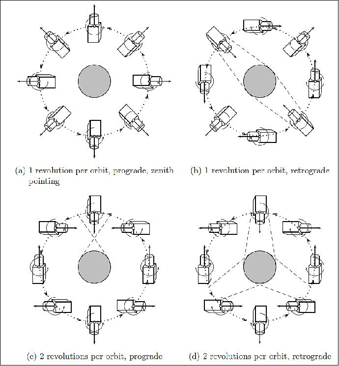
Legend to Figure 5: The dashed lines indicate possible Earth horizon observations. Depending on the intended observation region, different scanning velocities [(b), (c) or (d)] can be selected. Option (a) does not yield any Earth horizon observations.
Telescope Design
The µROSI telescope features an X-ray focusing optics consisting of 12 nested mirror shells made of electroformed Nickel with gold coating. The mirror shells are manufactured by the company Media Lario with custom-made mandrels.
Detector: The detector used for the telescope is a silicon drift detector (SDD) with high spectral resolution and without any spatial resolution. The detector requires a stable working temperature of about -15ºC in order to achieve its nominal spectral resolution. For this purpose, the µROSI telescope features a completely passive detector cooling subsystem. It includes a LCS (Latent Cold Storage) that contains a phase change material and provides a stable temperature during eclipse phases.
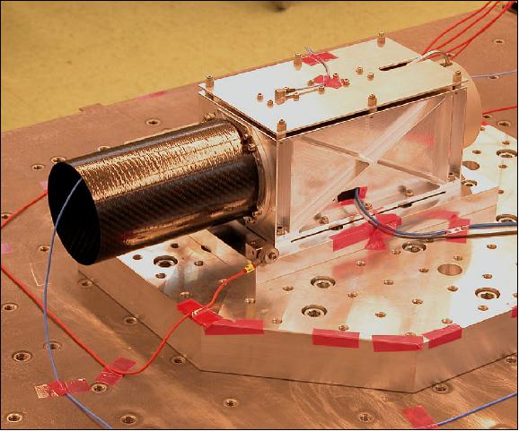
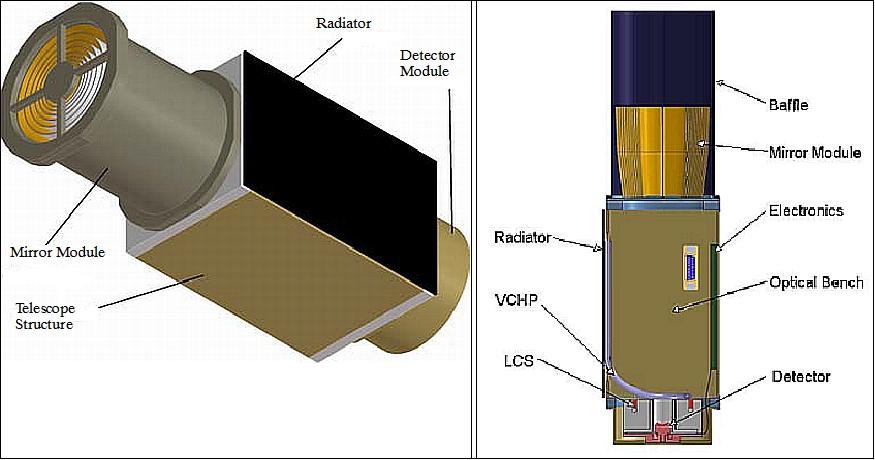
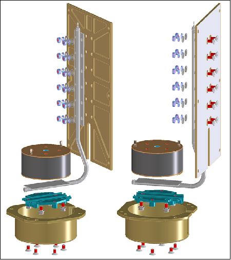
Figure 8 shows an exploded view of the telescope design. The 12 nested mirror shells are mounted on a titanium mechanical interface and screwed on top of the optical bench. The optical and thermal baffle, a CFRP (Carbon Fiber Reinforced Polymer) tube, prevents stray light from entering the mirror system and reduces thermal losses due to radiation. On the bottom side of the telescope is the detector module, which is mounted on the LCS for thermal stability. The LCS is mounted to the optical bench with a glass filled PEEK insulator. The aluminum heat pipe provides the thermal interface to the radiator, which is mounted on the back side of the telescope on thermally insulating bushings. The front side of the optical bench is mounted to the satellite with four M5 screws. A removable cover provides access to the inside of the optical bench, where the electronics is accommodated. - The µROSI electronics consists of two separate PCBs (Printed Circuit Boards), the power board and the main board.
Legend to Figure 8: The 12 nested mirror shells are protected against optical stray light with a CFRP baffle. The radiator is mounted with thermal insulators facing into space away from the satellite. A heat pipe connects it to the LCS unit on which the detector is mounted. The electronics unit is mounted inside the structure and is accessible via a removable cover plate. The structure is made of solid aluminum.
TCS (Thermal Control Subsystem): The TCS of µROSI manages the temperatures of all telescope components. The main task is to maintain the temperatures in the specified limits (Table 1).
The most critical components in the telescope when it comes to temperatures are the detector and the mirror. The mirror is subject to thermal stress and deformation due to its high view factor to the cold space background. Thus, a resistive heater is applied on the mirror interface structure to heat the mirror shells in case the temperature is too low.
Component | Operating temperatures (º) | Non-operating temperatures (º) | ||
minimum | maximum | minimum | maximum | |
Structure | +10 | +35 | -100 | +80 |
Mirror module | +10 | +35 | +10 | +35 |
Detector | -18 | -14 | -40 | +50 |
Electronics | +15 | +35 | -40 | +50 |
The detector requires low, very stable temperatures to achieve the best spectral resolution. The detector is therefore cooled passively with a dedicated radiator. The radiator is mounted on the optical bench with thermal insulating spacers. The outward surface is painted white, the inward surface is covered with MLI (Multi-Layer-Insulation ) foil. The optical properties of the thermal surfaces are listed in Table 2.
Component | α | ε |
White paint | 0.20 | 0.88 |
Black MLI | 0.93 | 0.84 |
Heat is transported to the radiator via a constant conductance heat pipe. The heat pipe tube is an extruded aluminum profile with grooves. The profile was developed by the MPE for the eROSITA (extended Roentgen Survey with an Imaging Telescope Array) camera cooling system. Several heat pipes have already been manufactured and tested at the MPE during the eROSITA qualification campaign. However, using the same heat pipe profile for µROSI and flying the heat pipe in space would again raise the technological readiness of this product before the eROSITA telescope is launched. Thus, the small miniature X-ray telescope serves as a technology demonstrator for the full-size eROSITA telescope.
The LCS is the thermal/mechanical interface between the heat pipe and the detector to provide the necessary temperature stability at the detector while the radiator temperature changes during the spacecraft orbit. A backup heater is applied on the LCS to prevent the PCM from complete freezing.
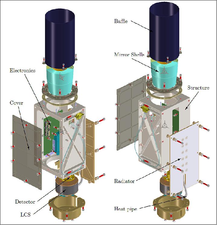
Figure 9 shows an exploded view of the µROSI TCS subsystem. The LCS is a cylindrical container that is mounted to the optical bench with a thermal insulator. It provides a mounting interface for the detector assembly. The bent heat pipe connects the LCS thermally to the radiator. The radiator features a cut-out section to allow the heat pipe to over-shoot. This is necessary to bypass the optical bench structure (not shown in Figure 9). In this configuration, the µROSI TCS can be completely assembled and tested, including the detector assembly, if required. For testing, the whole assembly is tilted so that the bent heat pipe can be tested horizontally to avoid gravitational effects in the heat pipe working fluid.
LCS (Latent Cold Storage): The LCS is basically a container filled with a PCM (Phase Change Material) that has a phase change at the desired stable temperature. Excessive heat can be stored using the latent heat of fusion ΔH during a phase change from liquid to solid at temperature TS.
Latent heat storages are widely used in space applications with operating temperatures typically ranging from +20 ºC to +50ºC. Typical PCMs for these temperatures are:
- Paraffins
- Salts
- Fatty acids
In 2008, a concept for a cooling system for the eROSITA cameras at -80ºC was published at the ICES conference in San Francisco which included a latent cold storage. At that time, eROSITA was still planned as a LEO mission. This implied high temperature changes at the radiators while the camera temperature was required to be stable within ±0.5ºC. The µROSI telescope was intended as a technology demonstrator for a low temperature LCS. Meanwhile, the eROSITA mission is scheduled for a flight to Lagrangian point L2 some 1:5 x10⁶ km from Earth opposite from the Sun-Earth direction. With virtually no Earth albedo radiation at L2 and very stable thermal conditions, the LCS concept for eROSITA has become obsolete.
However, for any LEO mission with high temperature differences in the eclipse phase, the Earth albedo and direct sunlight on the one hand, and stable low temperature requirements on the other hand, latent cold storages might be suitable. The advantages are:
- Temperature stability: Temperature stability of TS0:5 C are feasible.
- No power: A LCS requires no electrical power to maintain a stable temperature
- Scalability: The stored thermal energy is proportional to the PCM mass
- Reversibility: The phase change is 100% reversible without degradation
- Unlimited lifetime: Low leak rates provided, the lifetime of a LCS is practically unlimited
- High reliability: Apart from potential container leakages, there is absolutely no other source of error (no electronics, no valves)
- Failure tolerance: In case that the targeted environmental constraints can not be maintained, the LCS works as a stabilizing thermal capacitance.
The SDD (Silicon Drift Detector) used for µROSI requires stable, low temperatures in order to achieve a good spectral resolution. And, as the available power onboard a microsatellite is always a rare asset, it was decided to design the µROSI telescope with a LCS cooling system.
LCS design: A good LCS design should satisfy the following requirements:
- Vacuum-tight PCM containment with low leak rates
- High internal volume
- Low heat losses
- Two separate mechanical interfaces
- Minimum thermal conduction between mechanical interfaces
- Maximum heat exchange between mechanical interfaces and PCM.
The demand for low losses and high internal volume would suggest a spherical shape, as a sphere always has the lowest surface area per unit volume. But realizing a mechanical interface on a sphere is rather difficult, so that a cylindrical shape seems to be the best compromise.
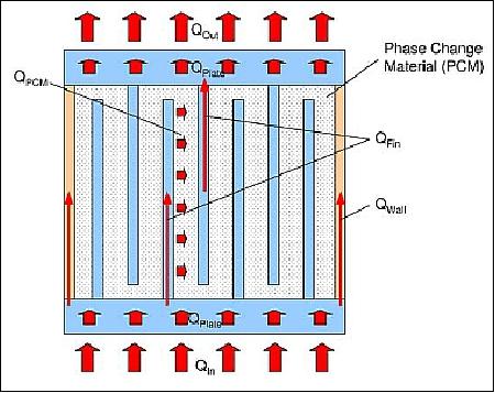
Figure 10 shows the heat fluxes in a LCS container. To achieve good thermal conduction between the flat interface surfaces and the PCM, fins protrude from the top and bottom. The heat flux through the cylinder wall QWall should be minimized to improve the heat exchange between the interface plates and the PCM. This can be achieved by reducing the wall thickness or increasing the cylinder length.
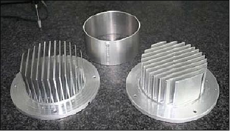
Figure 11 shows the main parts of the first latent cold storage prototype made from aluminum AlMgSi1. The plates and fins were milled of a single piece to achieve optimum thermal conductivity. The Ø 100 mm cylinder wall is only 1 mm thick and was welded to the plates. Threaded through holes in one plate could be used for filling and venting. Screw caps with Teflon PTFE (Polytetrafluoroethylene) washers were used for sealing the filling holes. In this way, different PCMs could be tested easily. The LCS was equipped with heaters and temperature sensors.
While the prototype LCS was an aluminum container, the µROSI flight model LCS container consists of copper fin plates and stainless steel cylindrical walls. This has the benefit that the fin plates have higher conductivity, improving the heat exchange and the container wall has less conductivity compared to an all aluminum container. The drawback is that this design increases the LCS mass.
Since the energy resolution of the µROSI detector depends on the temperature, the thermal control subsystem is critical for the success of the scientific mission. The TCS was designed to maintain a stable detector temperature of -15ºC in a SSO orbit. The key components are the heat pipe and the specifically developed LCS (Latent Cold Storage). The system works completely passive without the need of electrical power. 1-Octanol was successfully tested and was chosen as the phase change material in the LCS. The µROSI heat pipe also has been tested successfully using the same working fluid as the eROSITA camera cooling heat pipes.
Instrument mass, power consumption, supply voltage | < 3.0 kg, < 3.0 W, 15 V |
Mirror diameter | 80 mm |
Focal length | 240 mm |
Effective detector area | 20 mm2 |
FOV (Field of View) | 1º |
Energy resolution | 128 eV @ -20ºC, Mn-Kα (5.90 keV) |
Planned survey time | 1 year |
The key components of the µROSI telescope, the detector and the X-ray mirror, have been verified and the performance parameters have been measured. It could be shown that the detector, together with the custom-made electronics, provide sufficient energy resolution to measure spectra in the soft X-ray bandwidth. The focusing capabilities of the Wolter-1 approximation double-cone mirror shell has been verified by X-ray measurements.
In order to check, whether µROSI is able to achieve its primary mission objective of measuring at least one hundred bright X-ray sources, an initial simulation has been conducted. The simulation is based upon the ROSAT all-sky survey bright source catalog. The energy resolution of the telescope has been omitted in this simulation. Figure 12 shows how a celestial map from the µROSI all-sky survey could look like.
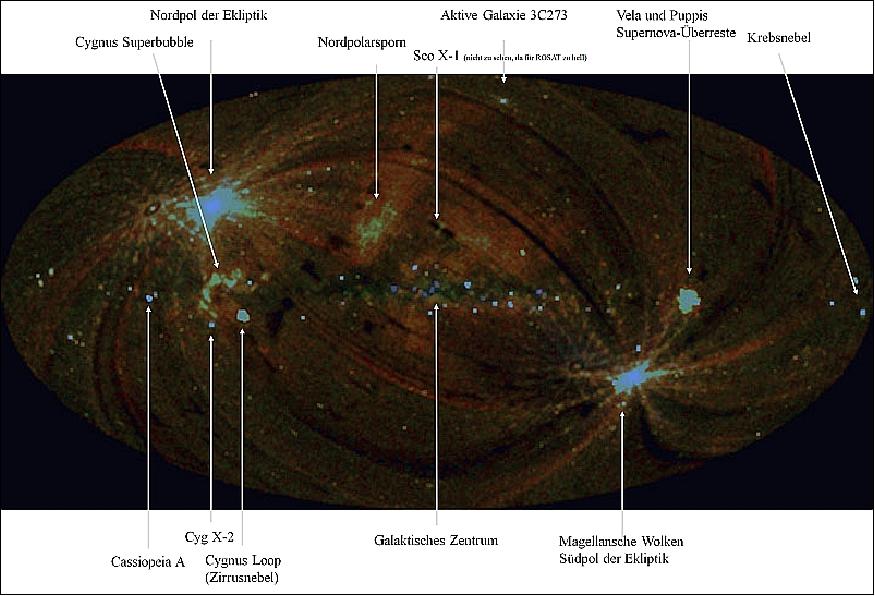
Legend to Figure 12: The blue color indicates hard X-rays and the red color indicates soft X-rays. The intensities are not normalized to the exposure time, so that the observation poles appear brighter.
AIS (Automatic Identification System)
The AIS receiver (radio communication system) is provided by LuxSpace of Luxembourg (a daughter company of OHB Technology AG of Bremen) with the objective to monitor the maritime shipping traffic.
AIS for maritime vessels introduced by the IMO (International Maritime Organization) is a navigation aid and basically an anti collision system for vessels at sea. Vessels are broadcasting messages (position reports and short messages with information about the ship and the voyage) on two channels in the maritime VHF band on a regular basis to neighboring vessels for collision avoidance, and to shore stations for VTS (Vessel Traffic Services). AIS messages can also be received by a VHF receiver in space for wide area observation of maritime activity. According to the International Association of Maritime Aids to Navigation and Lighthouse Authorities (IALA), the purpose of AIS is "to improve the maritime safety and efficiency of navigation, safety of life at sea and the protection of the marine environment."
GPS Receiver
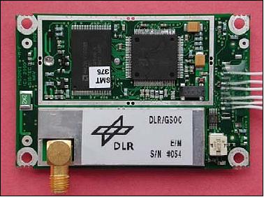
The Phoenix miniature GPS receiver, provided by DLR/GSOC (German Aerospace Center/German Space Operations Center), is being used for on-board timing and real-time orbit determination. Phoenix uses the GP4020 chip to achieve a higher integration level and lower power consumption. The Phoenix receiver, a 12-channel single-frequency device (GPS L1 C/A-code), makes use of the industrial SigTec MG5001 board using a proprietary software of DLR/GSOC for space and high-dynamics applications. 13)
At a size of 50 mm x 70 mm and a power consumption of less than 0.8 W, the receiver is ideally suited for nano- and microsatellites with restricted onboard resources. In case of very tight power budgets, the receiver can also be operated intermittently.
The Phoenix receiver has been tuned for highly accurate tracking, navigation and timing and provides the following services:
- Synchronization of all measurements with integer GPS seconds
- A pulse-per-second signal aligned with the integer GPS second to the order of 0.2 µs
- The use of a 3rd order PLL with FLL assist for accurate carrier tracking at high dynamics
- The provision of carrier phase measurements with integer ambiguities for precise relative navigation
- The use of a carrier aided narrow-band DLL for code tracking and low-noise pseudorange measurements
- The computation of carrier phase smoothed pseudoranges and carrier based range-rate.
The Phoenix receiver is being controlled by the main controller over an asynchronous serial interface. To save energy the module will not always be switched on, it will only be used at times to precisely determine the satellite's orbit.
CMOS Camera
Three separate CMOS modules by Omnivision are being used with a customized interface board. The detector size is 450 x 600 pixels. The three cameras are being used for test purposes.
Reference
1) Ludwig Orgler, Dieter Seiwald, Elmar Weiss, Ignacio Gutiérrez-Cañas, Indulis Kalnins, Lars Tiedemann, "The challenging South Tyrolean ‘Max Valier' nano satellite with X-ray amateur telescope and AIS experiments," Proceedings of the 60th IAC (International Astronautical Congress), Daejeon, Korea, Oct. 12-16, 2009, IAC-09.B4.6B.9
2) http://gobmeran-satellit.jimdo.com/
3) Indulis Kalnins, Willem Bode, "AISat, Venta-1 and Max Valier nanosatellite based on QuadSat platform," Proceedings of IAC 2011 (62nd International Astronautical Congress), Cape Town, South Africa, Oct. 3-7, 2011, paper: IAC-11.B4.7.5
4) Sandra Zuccaro, Ferdinand Heidegger, Carlos Burnett, Willem Bode, Indulis Kalnins, "Attitude Control on the Max Valier Student Satellite: A Project by High School Students," Proceedings of the 63rd IAC (International Astronautical Congress), Naples, Italy, Oct. 1-5, 2012, IAC-12-E1.2.2
5) "PSLV-C38 / Cartosat-2 Series Satellite," ISRO, June 23, 2017, URL: http://www.isro.gov.in/launcher/pslv-c38-cartosat-2-series-satellite
6) "Indian Launch Manifest of April 15, 2017," URL: http://www.sworld.com.au/steven/space/india-man.txt
7) "PSLV-C38 / Cartosat-2 Series Satellite Mission: All 31 Satellites separated successfully," ISRO, June 23, 2017, URL: http://www.isro.gov.in/update/23-jun-2017/pslv-c38-cartosat-2-series-satellite-mission-all-31-satellites-separated
8) Dave Williamson, "Small Satellites: The Execution and Launch of a GPS Radio Occultation Instrument in a 6U Nanosatellite," 33rd Space Symposium, Colorado Springs, CO, USA, April 3-6, 2017, URL of presentation: https://www.spacesymposium.org/wp-content/uploads/2017/10/Williamson_Dave_GPS_Radio_Occultation_Talk-v1.pdf
9) Lars Tiedemann, Maria Fuermetz, Peter Predehl, Hans-Peter Roeser, "The development of µROSI - Micro Roentgen Satellite Instrument, "Proceedings of the 64th International Astronautical Congress (IAC 2013), Beijing, China, Sept. 23-27, 2013, paper: IAC-13-B4.2.6
10) Lars Tiedemann, Elias Breunig, Vadim Burwitz, Maria Fuermetz, Gisela Hartner, Walter Kink, Benedikt Menz, Peter Predehl, Hans-Peter Roeser, Martin Schlecker, Giuseppe Valsecchi, "The Development of the µROSI X-ray Telescope," Proceedings of SPIE, Spaceborne Experiments and Missions I, Vol. 8859, 'UV, X-Ray, and Gamma-Ray Space Instrumentation for Astronomy XVIII,' 885905, San Diego, CA, USA, September 26, 2013, doi:10.1117/12.2023973
11) Lars Tiedemann, "The Development of the Miniature X-Ray Telescope µROSI," Thesis, University of Stuttgart, July 2, 2014, URL: http://elib.uni-stuttgart.de/bitstream/11682/3973/1/Dissertation_Lars_Tiedemann.pdf
12) Elias Breunig, "The Micro Roentgen Satellite Instrument," Proceedings of the 61st IAC (International Astronautical Congress), Prague, Czech Republic, Sept. 27-Oct. 1, 2010, IAC-10.B4.2.5
13) "Phoenix Spaceborne GPS Receiver," URL: http://www.dlr.de/rb/Portaldata/38/Resources/dokumente/GSOC_dokumente/RB-RFT/Phoenix_DataSheet_v11.pdf
The information compiled and edited in this article was provided by Herbert J. Kramer from his documentation of: "Observation of the Earth and Its Environment: Survey of Missions and Sensors" (Springer Verlag) as well as many other sources after the publication of the 4th edition in 2002. - Comments and corrections to this article are always welcome for further updates (eoportal@symbios.space).