M3MSat (Maritime Monitoring and Messaging Microsatellite)
EO
CSA
Maritime Monitoring and Messaging MicroSatellite (M3MSat) was a technological demonstration mission based in Canada, and jointly funded by the Department of National Defence (DND), the Canadian Space Agency (CSA), exactEarth and COM DEV Ltd. M3MSat aimed to provide maritime traffic monitoring to ensure security, safety and sovereignty of Canadian maritime regions. The mission was launched in June 2016 with a target design life of two years. M3MSat completed all mission objectives at the end of May 2021, and was handed over to a private company to commence commercial service missions.
Quick facts
Overview
| Mission type | EO |
| Agency | CSA |
| Launch date | Jun 2016 |

Summary
Mission Capabilities
M3MSat utilised the concept of Software Defined Radio (SDR) on its payloads, where pre-existing components found on everyday hardware have been repurposed programmatically to be utilised on satellite systems to support communications systems. This was particularly useful as it was inexpensive to implement. Onboard the satellite was an Automatic Identification System - Payload Electronics Module (AIS-PEM), Low Data Rate System - Payload Electronics Module (LDRS-PEM) and Dielectric Deep Charge Monitor (DDCM).
AIS-PEM was used for identifying ships from space based on the self-reporting nature of the AIS network. The information provided by the ships include its identification code, position and heading, time and payload. LDRS-PEM established two-way communications at a low data rate and demonstrated its feasibility for machine-to-machine communications. DDCS was a technology demonstration payload designed to monitor the electric potential of a dielectric sample due to space environment-induced charging.
Performance Specifications
AIS-PEM established communications using Very High Frequency (VHF) radio and received the signals through the VHF AIS antenna. LDRS-PEM collected data from ground terminals with a C-Band link, capable of converting Ultra High Frequency (UHF) signals from 400 MHz to 162 MHz, and communicated with Canadian Department of Fisheries and Oceans (DFO) buoys.
M3MSat operated in a sun-synchronous circular orbit, at an altitude of 515 km and an inclination of 97.5°.
Space and Hardware Components
M3MSat was developed in a partnership between COM DEV Ltd based in Ontario, along with the University of Toronto, Institute for Aerospace Studies/Space Flight Laboratory (UTIAS/SFL) in Toronto. THe satellite bus used was the Advanced Integrated Microsatellite (AIM) multi-mission bus, which is cost-efficient and highly flexible. Furthermore, there was an Attitude Determination and Control System (ACDS) onboard, along with an Electrical Power Subsystem (EPS) and a Command & Data Handling Subsystem (CDHS) which provided redundancy for the onboard Controller Area Network (CAN) buses.
M3MSat (Maritime Monitoring and Messaging Microsatellite)
Overview Spacecraft Launch Sensor Complement Ground Segment References
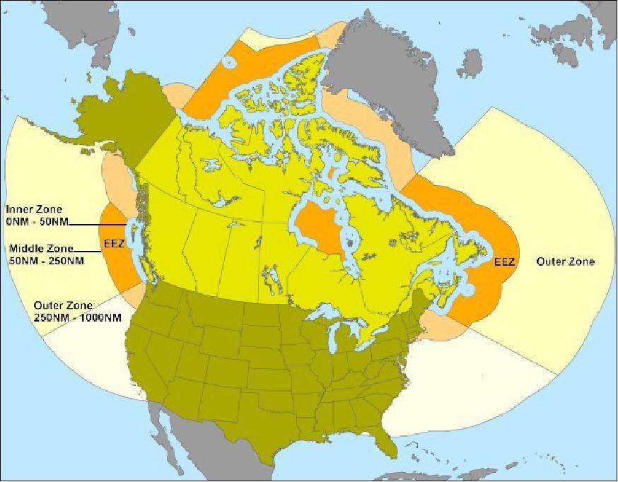
M3MSat is a Canadian technology demonstration mission jointly funded by the Department of National Defence (DND), the Canadian Space Agency (CSA), exactEarth and COM DEV Ltd. The overall objective is to provide spaceborne services in support of Canadian sovereignty, security, safety and communications needs within the territorial and maritime regions of Canada and beyond. Maritime surveillance of shipping traffic poses a considerable challenge to the CF (Canadian Forces). M3MSat will collect and report for DRDC (Defence Research and Development Canada) shipborne data. The Canadian coastline has a length of 243,772 km, the longest of any nation in the world. 1) 2)
The M3Msat mission was approved in 2006-2007 by the Department of National Defence (DND) and CSA as a joint microsatellite mission for maritime monitoring and messaging. In June 2008, COM DEV International Ltd. of Cambridge, Ontario was awarded a contract to design, build and launch the M3MSat for the Government of Canada. M3MSat is a follow-on project of the very successful CanX-6 / NTS-1 nanosatellite mission which was launched on April 28, 2008. - The M3MSat mission is the second joint CSA - DND microsatellite mission (the first one being NEOSSat).
The M3MSat project is designed to satisfy four mission objectives:
1) augment existing maritime surveillance capabilities through the space-based monitoring of ship Automatic Identification System (AIS)
2) foster Canadian capabilities by providing an opportunity for the contractor to propose and demonstrate a new technology for a secondary payload
3) provide a flight opportunity for Canadian industry to space qualify new technology and to establish flight heritage
4) the primary mission objective is to provide maritime surveillance for both commercial customers, and for the Canadian government, by detecting AIS messages from space.
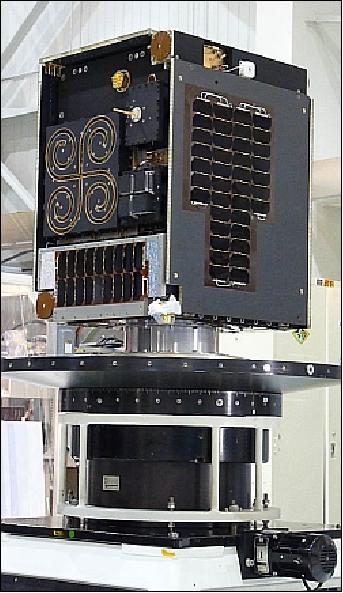
In the summer of 2012, the M3MSat project is in the assembly, integration and test phase. The mechanical dry-fit of the assembly has been performed, at which point the structure was dismantled to allow the individual components to be populated. The bus equipment has been integrated to the panels and harnessing, and is undergoing initial tuning and system testing.
Spacecraft
M3MSat is being developed in a partnership between COM DEV International Ltd. of Cambridge, Ontario and UTIAS/SFL (University of Toronto, Institute for Aerospace Studies/Space Flight Laboratory) of Toronto, Canada , with COM DEV as the prime contractor. M3MSat is based on the COM DEV AIM (Advanced Integrated Microsatellite) multi-mission bus which is a highly flexible and cost-effective platform that meets or exceeds the CSA's MMMB (Multi-Mission Microsatellite Bus) specification. 3) 4) 5) 6) 7) 8) 9) 10) 11)
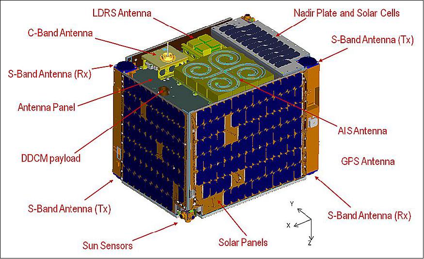
M3MSat with the AIM bus is a microsatellite with dimensions of 0.6 x 0.6 x 0.8 m and mass of ~85 kg. In addition to the primary AIS receiver payload, M3MSat will also carry the LDRS ( Low Data Rate System) payload used to demonstrate a satellite based AIS data relay capability and a DDCM (Deep-Dielectric Charging Monitor) payload which is an experiment to observe spacecraft charging and material behavior.
In the M3MSat partnership, COM DEV as the prime contractor, is responsible for spacecraft integration and testing as well as development of the spacecraft structure, the TT&C subsystem and the AIS and LDRS payloads. SFL was contracted to provide the spacecraft power, attitude determination and control and the command and data handling subsystems.
M3MSat is a PPP (Public Private Partnership) mission. Funding for the mission is provided by DRDC (Defence R&D Canada), CSA (Canadian Space Agency), exactEarth and COM DEV Ltd. In addition, the CSA is providing the DDCM payload while spacecraft operations will be performed by the DRDC. AIS data from M3MSat will be jointly utilized by the Canadian government for coastal monitoring and commercially by exactEarth for their global AIS data services.
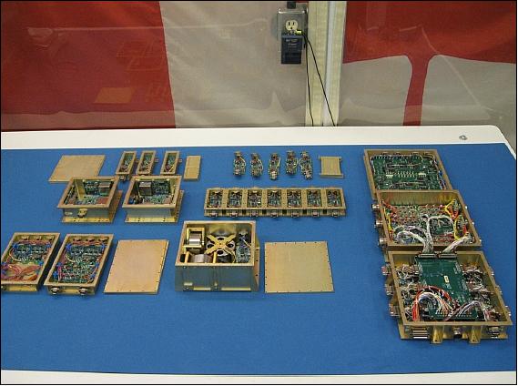
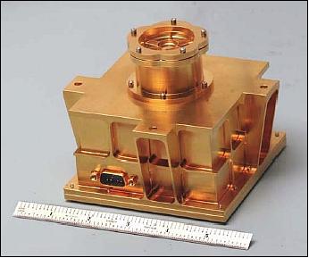
Bus: The bus structure consists of a set of panels, each of which provides support for the various subsystems that make up the spacecraft. During integration, individual modules are installed into aluminum boxes both for physical isolation and EMC control. Several of the flight modules for the C&DH, power and ADCS subassemblies are shown in Figure 3.
These boxes are then bolted to panels (generally in stacked configurations), and a wiring harness is installed. Interconnection is simplified by the fact that all modules use a common connector interface that carries bus power and connection to the redundant CAN (Controller Area Network) bus. Finally, the panels are brought together, and are bolted together; this creates the spacecraft primary load-bearing structure. This design allows for easy integration and debugging: modules can be added one by one, and any difficulties resolved before adding more modules. Should problems arise late during the AI&T (Assembly, Integration and Test) process, it is relatively easy to open the spacecraft up again and debug.
The AIM bus is fully redundant. The majority of the redundancy is provided by two independent strings, each of which contains a full complement of the systems required to operate the spacecraft.
ADCS (Attitude Determination and Control System): The ADCS provides full 3-axis stabilized control (zero-momentum implementation). The ADCS is designed to perform nadir pointing to an accuracy of better than 5º, and can execute a 180º slew in less than 15 minutes. There are no pointing stability requirements for the mission.
The attitude determination suite of the AIM bus consists of a pair of 3-axis magnetoinductive magnetometers, a pair of 3-axis MEMS rate sensors, and a set of six dual-axis sun sensors. The magnetometers have a full-scale range of ±100 µT, and, after calibration, a mean error of < 35 nT over the full range. The rate sensor assembly will produce a random walk of less than 7º over the worst-case expected eclipse period (40 minutes) and the sensor rate bias drifts less than 0.3º/s over the operational temperature range. Each sun sensor has a field of view of 140º, and reads out a sun vector with a calibrated accuracy of 0.1º over the full field of view.
The attitude actuation suite consists of a set of reaction wheels, and a set of magnetic torque rods. The reaction wheels are organized as two redundant sets of three orthogonal wheels each. Each wheel has a momentum capacity of 80 mNms at 1000 rad/s angular speed, and can generate a maximum torque of 5 mNm. The torque rods are capable of 15 Am2 each and are used for initial detumbling, and for reaction wheel desaturation. Each torque rod is dual-wound, with each winding providing enough dipole to desaturate the wheels.
The ADCS software is based on SFL's OASYS (On-orbit Attitude System Software) ADCS suite, which has extensive flight heritage on the CanX-2 and AISSat-1 mission. OASYS consists of an EKF (Extended Kalman Filter), which reads information from the attitude sensor suite, and estimates the current attitude of the spacecraft. This estimate is then compared against the target quaternion, and the error is filtered through a PID controller. Based on the filtered error estimate, target wheel speeds are computed, and are transmitted to the wheels. Simulations of the M3MSat mission, using a high-fidelity model of the spacecraft and the disturbance environment, indicate that a pointing error between 2.5º and 5º (3σ) can be achieved.
EPS (Electrical Power Subsystem): The system was designed by UTIAS/SFL and builds on heritage from numerous successful spacecraft missions. The EPS features a series peak power tracking topology which is built around several modular components. The power system provides 28 switched and 4 unswitched outputs and is capable of providing an average power 70 W and allocated 15 W average power consumption to either AIS-PEM or LDRS-PEM.
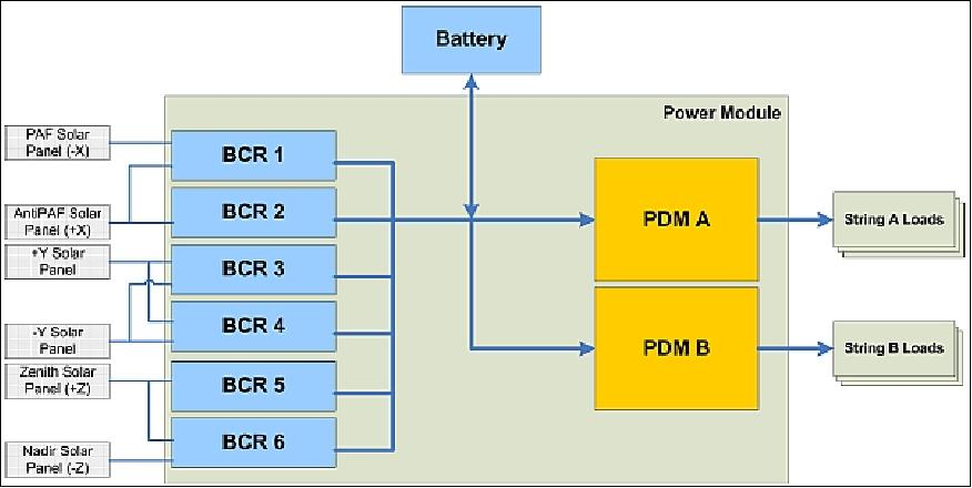
The AIM bus ultimately derives its power from a set of six body-mounted solar panels. Triple junction GaInP/GaAs/Ge solar cells are being used with 28% efficiency. PPT (Peak Power Tracking) of the solar panels and battery charge regulation is provided by six BCR (Battery Charge Regulators). Each BCR operates independently of the others and any number of the modular units can be combined in parallel to charge the battery. Each BCR connects to one half of the solar cell strings on two opposite sides of the spacecraft to minimize the impact of failure of any one BCR. This also reduces the input requirements of each BCR as the two panels will never be simultaneously illuminated (with the exception of Albedo).
Two PDMs (Power Distribution Modules) are provided for redundancy. The PDM provides both switched and unswitched outputs. Unswitched outputs are used for subsystems which are associated with the reception of telecommands from the ground: the command receivers, and the command decoders. These outputs are always on whenever the spacecraft is on; in the event of an over-current fault, the outputs briefly turn off, and then turn on after a short delay. This is intended to allow transient faults to clear via a power cycle. Switched outputs are off by default at spacecraft power-up. Upon receipt of a command the load can be turned on or off. As with the unswitched outputs, the switched outputs are protected against overcurrent fault; in the event of a fault, the switch is turned off, and the event is logged.
A Li-ion battery with a capacity of 17.4 Ah is providing power during the eclipse phase of the orbit. The battery consists of multiple Li-Ion cells in an 8S3P configuration which allows the battery to operate at the required bus voltage and makes the battery tolerant to the failure of any one cell. In this power system architecture the battery is connected directly to the power bus with no discharge regulation. The low battery impedance contributes to power system stability and suits loads that require intermittently large peak power. 13)
C&DHS (Command & Data Handling Subsystem): The AIM bus uses a distributed C&DHS architecture. The majority of all commands and telemetry are carried over a pair of CAN buses. By using two buses, the spacecraft can achieve redundancy. By default, each node listens to the primary CAN bus. If it does not receive a special synchronization message within a specified timeout, it switches to the redundant bus and begins listening. This process repeats with the node switching buses until it receives the synchronization message. The synchronization messages are generated by the communications node (see below); in the event of a bus failure, an operator would command the communications node to switch buses. Within 60 seconds of a bus switch command, all units in the spacecraft will switch to the new bus, and receive all of their commands on that bus.
The C&DHS includes a pair of OBCs: 1) a HKC (Housekeeping Computer) responsible for telemetry gathering, storage and telecommand execution as well as onboard time management; 2) an ADCC (Attitude Determination and Control Computer) responsible for processing inputs from the attitude sensors, executing ADCS algorithms and sending control commands to the attitude actuators. In the event of a failure of either of these computers, the software on the remaining unit can be merged, so that the single computer performs both tasks, albeit with reduced memory and throughput margins. Each OBC is based on a 32 bit microprocessor, and has 2 MB of error-corrected RAM, as well as 2 GB of non-volatile (flash) storage.
The HKC software is responsible for collecting and storing spacecraft telemetry, providing time synchronization and the storage and release of time-tagged commands. Both the HKC and ADCC software is based on SFL's CANOE operating system. This is a priority-driven preemptively multi-tasking operating system, with substantial flight heritage (CanX-2, NTS, and AISSat-1). The use of preemptive multi-tasking substantially simplifies software development, as independent functions can be broken down into separate threads, and thus isolated from each other.
A large number of the spacecraft units are either legacy devices, or are COTS (Commercial Off-The-Shelf) hardware which are not equipped with a CAN interface or do not use the protocol suite that is used on the AIM bus. In order to adapt these devices for use on the AIM bus, a CIM (CAN Interface Module) was developed. The CIM is configured to use a standard RS-485 or RS-232 serial interface and simply bridge data between the serial ports and the CAN bus. It is the responsibility of the software that communicates with the device to provide interpretation of the device's data stream.
Finally, the payload is accommodated via a CDSU (Centralized Data Storage Unit). The CDSU can be thought of as a general-purpose bus terminal: it provides a variety of inputs and outputs that can be used to control payloads, and to store payload telemetry. The CDSU provides discrete digital inputs, analog inputs, thermistor inputs, pulsed power outputs (both at 12 V and at the bus voltage), and multiple RS-485 input/output ports. It also provides a high-speed (1.25 Mbit/s) serial input, which can be buffered in 2 GB of on-board non-volatile storage; the CDSU can then downlink the data at high speed (4 Mbit/s) when the spacecraft is in view of a ground station. Note that, being a part of the payload accommodation, the CDSU is normally not redundant.
RF Communications
Fully redundant S-band receivers and transmitters are used for the TT&C (Telemetry, Tracking and Command) function, based on COM DEV's flight-proven hardware. The TT&C subsystem provides 4π steradian coverage with a pair of receive and a pair of transmit patch antennas arranged on opposite corners of the spacecraft. The two S-band transceivers are connected to the receive antennas via a hybrid (which routes each antenna to each receiver), and to the transmit antennas via a coaxial switch. Each transmitter can be routed to either of the transmit antennas. The transmitter provides up to 2.2 W of RF power, and supports data rates between 32 kbit/s and 6.25 Mbit/s, using BPSK, QPSK, and OQPSK modulation. The data is downlinked in ECSS (European Cooperation for Space Standards) format. The receiver supports a rate of 4 kbit/s.
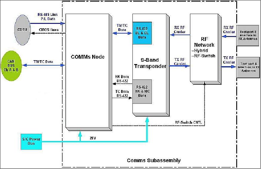
Each communications node is attached to both receivers, but only to one transmitter. When data is received over the radio link, the communications node performs bit, word, and frame detection, error correction, and packet integrity checking. Valid packets are examined, based on their destination address. Packets containing hardware-decoded commands or TT&C subsystem commands are immediately acted on by the communications node. All other packets are formatted using the correct framing, and are transmitted on the CAN bus. This enables the ground to communicate directly with any unit in the spacecraft (power system, reaction wheel, etc.) without first routing the data through an OBC.
Data arriving on the CAN bus that is destined for the ground, or via the high-speed link from the payload (via the CDSU), is broken down into frames and ECSS formatting is added. If selected, error-correction coding is added, and the resultant data is sent to the transmitter for downlink.
The new S-band antennas will allow M3MSat to communicate with ground stations, and the four GPS patch antennas will allow the satellite to receive GPS signals to determine their position in space. A secondary communications payload will be operated on M3MSat to demonstrate a range of low data rate applications that can support Canadian civil needs as well as commercial requirements.
C-band downlink of AIS payload data: The two AIS chains each have a C-band transmitter and cross-strapping to provide a measure of control over the downlink of data. The raw data is transmitted to the ground through a dedicated 20 Mbit/s C-band link.
It is possible to also use the communications subsystem for downloading payload data and this is the case for the tertiary payload. However the primary (e.g., AIS) and secondary payload data are transmitted routinely through a higher speed C-Band downlink.
Total spacecraft mass, size | 80 kg, 80 cm x 60 cm x 60 cm |
Propulsion | none |
Mission life | 1 year min (2 year goal) |
Orbit | 600-850 km altitude |
Payload power | 40 W (average) |
Bus rail voltage | 26 ±6 V |
Attitude stabilization | 3-axis stabilized |
Attitude pointing control | 1º in pitch, roll, yaw |
On-board data storage | 2 GByte |
TT&C communications (S-band) | 4 kbit/s (uplink), 32 kbit/s to 6.25 Mbit/s (downlink) |
AIM multi-mission bus: In parallel with the development of the M3MSat mission was the design of the AIM multi-mission bus itself. The AIM bus is intended to be a generic microsatellite platform suitable for a wide range of space missions including Earth observation and science. The flexible nature of the bus is achieved through a combination of generic interfaces, modular avionics, reconfigurable power system, and a large payload volume and mass allocation. The AIM bus will be flight qualified with the launch of M3MSat and will provide a unique Canadian capability for the rapid deployment of new technologies, operational missions and science experiments in space.
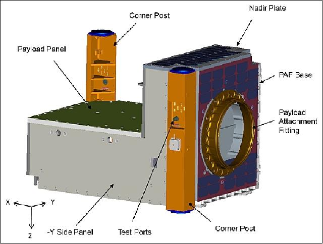
The AIM bus has a large payload bay for housing mission specific payloads (Figure 8). The payload area has dimensions of 53.5 cm x 54.5 cm x 28.5 cm with access to the +X, ±Y, and -Z panels for payload specific sensors or antennas. The payload mass allocation can be up to 25 kg which gives a payload to bus mass fraction of 40%. Payload thermal management is achieved with a combination of a well thermally-coupled corner post, accessible from the payload bay, customizable thermal coatings for the panels, and payload power ports that can be dedicated to heaters.
The AIM EPS (Electrical Power Subsystem) is highly modular and permits mission specific customization. The number and length of solar cells strings on each panel can be adapted to fit around sensors and antennas or to optimize power generation. The bus also supports the attachment of an optional deployable solar panel to further expand power generation capability. With body mounted panels alone, the bus is capable of producing between 80 W to 120 W on average, depending on the attitude and orbit for a particular mission with 50-60% of the power typically available for the payload. By default, six 3A power switches are dedicated to the payload(s) which can be further expanded with an additional power distribution module. Finally the battery mass and capacity can be traded depending on mission requirements in one of three possible configurations: 133 Wh/1.3 kg, 233 Wh/2.6 kg or 400 Wh/4 kg.
The payload communication and telemetry interfaces are also highly modular. A single payload interface module provides two RS4-85 channels, six 16 bit analog inputs, two thermistor inputs, six discrete inputs, six 12 V command lines and three 28 V switch driver command lines. Depending on the payload requirements, up to three payload interface modules can be utilized for a particular mission. These modules satisfy the CSA multi-mission bus interface requirements. The redundant multi-drop CAN bus used for housekeeping command and telemetry can also be extended to the payload and CIMs are available for payloads that do not support CAN or the bus protocols. Several options are also available for high speed non-volatile payload data storage.
Launch
M3MSat was launched as a secondary payload on June 22, 2016 (03:56 UTC) aboard a PSLV vehicle of ISRO (PSLV-C34 flight) from SDSC (Satish Dhawan Space Center) SHAR (main launch center of ISRO on the south-east coast of India, Sriharikota). The CartoSat-2C mission was the primary payload on this flight with a launch mass of 727.5 kg. The total mass of all satellites onboard was 1288 kg. 15) 16) 17)
Orbit: Sun-synchronous circular orbit, altitude altitude = 515 km, inclination = 97.5º, local time on descending node (LTDN) = 9:30 hours.
Replacement launch of M3MSat: On Oct. 1, 2014, COM DEV International Ltd. signed a contract with the Antrix Corporation (the commercial arm of ISRO) to launch the M3M satellite on the PSLV (Polar Satellite Launch Vehicle) from India in 2015. This contract reflects the replacement launch for the M3M satellite, which was withdrawn from its original launch slot on the Russian Soyuz rocket in July 2014 (with Meteor-M2 of Russia as the primary payload). The new contract was signed at the 65th IAC (International Astronautical Congress) in Toronto, Canada. 18)
Secondary Payloads on this Flight
• SkySat-C1, an imaging minisatellite of Terra Bella of Mountain View, CA, USA.
• GHGSat, a microsatellite (15 kg) of GHGSat Inc., Montreal, Canada
• BIROS (Bi-spectral InfraRed Optical System), a minisatellite 130 kg) of DLR, Germany.
- BIROS carries onboard the picosatellite BEESAT-4 (Berlin Experimental and Educational Satellite-4) of TU Berlin(1U CubeSat, 1 kg) and release it through a spring mechanism [ejection by SPL (Single Picosatellite Launcher) after the successful check-out and commissioning of all relevant BIROS subsystems]. After separation, it will perform experimental proximity maneuvers in formation with the picosatellite solely based on optical navigation.
• M3MSat (Maritime Monitoring and Messaging Microsatellite) of DRDC (Defence Research and Development Canada) and CSA (Canadian Space Agency).
• LAPAN-A3, a microsatellite (115 kg) of LAPAN (National Institute of Aeronautics and Space of Indonesia) Jakarta, Indonesia.
• SathyabamaSat, a 2U CubeSat of Sathyabama University (1.5 kg), India.
• Swayam, a 1U CubeSat of the College of Engineering (1 kg), Pune, India.
• 12 Flock-2p Earth observation satellites (3U CubeSats) of Planet Labs (each with a mass of 4.7 kg), San Francisco, CA.
Sensor Complement
Background: The M3MSat AIS payload is based on the SDR (Software Defined Radio) concept - a technique where components that have been typically implemented in hardware (e.g. mixers, filters, amplifiers, modulators/demodulators, detectors, etc.) are instead implemented by means of software in microprocessors. In other words, the radio is implemented on a software-based re-configurable platform and can be used to support various functions and signal schemes. Such software based solutions have several very promising advantages. A reconfigurable system allows multiple missions to use the same hardware by loading different application software. The software for each system can be stored in memory and can even co-exist or execute concurrently if desired. In addition, software defined communications systems can be remotely configured or updated, allowing for inexpensive bug fixes, upgrades or optimizations. This is extremely important for a spaceborne system. 21)
The emergence of SDR now allows for greater manipulation of the uplinked signals including; digital frequency conversions, adaptive modem/modcods, filtering, equalization, linearization; and steady improvements in the DSP (Digital Signal Processor) ‘engine' allows these function to be performed over increasing processed bandwidths.
SDR payloads, while having many advantages, do face some challenges in microsatellite payload applications:
1) Mass, power, and volume constraints for microsatellites
2) Resource reservation is required to make SDR useful for potential update during mission or reconfigurable for other missions
3) Bandwidth limit for remote software/firmware code update
4) Space radiation environment
5) What level of standardization SDR payloads should be adopted?
SDR requires a certain amount of resources to be reserved to support the potential future functionalities and flexibilities. For example, to make the SDR payload useful in supporting potential more complicated waveforms during a mission, a sizeable memory and possibly CPU/FPGA processing power, and DC power capability need to be reserved at the beginning of life (BOL) of the mission. That will directly translate to increased demands on the resources of the hosting satellite bus.
SDR as an attractive solution and is being applied to the payloads being developed by COM DEV for the Canadian M3MSat.
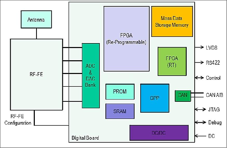
The M3MSat digital platform consists of a CAN bus networked, a high-speed DSP (Digital Signal Processor), implemented in a reprogrammable FPGA and a 32 bit fault tolerant RISC microprocessor. Extensive memory resources are provided, including 8 GByte of FLASH, 32 MByte of SDRAM and 128 kByte of boot PROM (Programmable Read-Only Memory). The two receive channels and the single transmit channel use ADC and DAC devices to sample and generate the IF signals. A selection of digital interfaces is provided to send and receive the processed data to and from the spacecraft platform and payload. These include SPI (Serial Peripheral Interface), HSDL (High Speed Data Link), HK (Housekeeping) and TT&C.
The SDR is capable of simultaneously processing sampled received IF signals, and generating and transmitting suitably modulated IF signals, to and from the RF/IF front end. The CPU runs RTEMS (Real-Time Executive for Multiprocessor Systems) V4.8 RTOS (Real Time Operating System). This open source OS has extensive heritage on space programs, including the MRO (Mars Reconnaissance Orbiter). A BSP (Board Support Package) is provided with the SDR board to enable COM DEV to develop their own specific algorithms running on the CPU and DSP. The BSP consists of software drivers for the CPU, example SDR algorithm designs for the FPGA, and extensive documentation (Ref. 21).
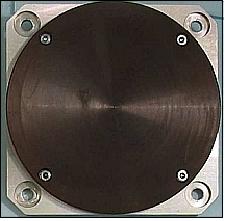
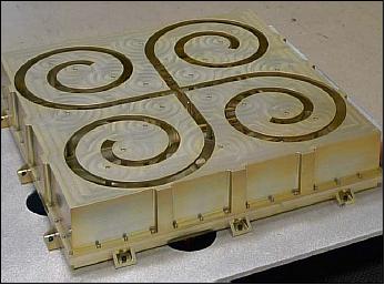
The primary objective of the mission is fulfilled through the use of redundant AIS payload chains. Each of these chains consist of a VHF antenna, specially designed to meet the mechanical volume requirements in addition to having stringent gain profile required to receive the AIS signals from space. As the antenna is large, approximately 30 cm x 30 cm, only one is used on for the mission. The AIS antenna was a joint development between the University of Waterloo and COM DEV. The signal is split and then passed to a VHF receiver built by COM DEV Europe. The receiver performs RF filtering, down-sampling and signal digitization. The RF spectrum is then recorded within a data recorder (a customized unit from Surrey Space Technology Limited). The raw data is transmitted to the ground through a dedicated 20 Mbit/s C-band link.
The two AIS chains each have a C-band transmitter and cross-strapping to provide a measure of control over the downlink of data. Nominally, the raw sampled spectrum will be downlinked; however, the system also allows real-time or post collection message extraction within the data recorder. The advantage is that this provides an in-orbit verification of processing capabilities with the potential of providing a method of minimizing the amount of data transmitted to the ground stations.
AIS-PEM (Automatic Identification System - Payload Electronics Module)
The AIS payload performs the spacecraft's primary mission of receiving AIS signals transmitted by ships from space. As part of the overall AIS signal processing system, the AIS receiver performs AIS signal reception, digitization, signal processing, storage, and transmission of the signal to ground for further processing.
The AIS signals are being used for integration into a RMP (Recognized Maritime Picture). AIS is a maritime self-reporting network intended to improve the safety at sea by having all ships greater than 300 tons continually transmit their location over VHF.
AIS requirements summary:
• International Maritime Organization (IMO) decree, implemented through the SOLAS (Safety of Life at Sea) convention. The ship information includes (but not limited to):
- MMSI (Maritime Mobile Service Identity)
- Position heading
- Time
- Rate of turn
- Cargo
• VHF maritime band with GPS
• Reports are generated approximately every 6 seconds (depending on speed).
The objective of AIS-PEM is to demonstrate the full capability of advanced spaceborne AIS technology developed by COM DEV. The payload consists of software configured RF front-end which features a tunable carrier frequency, and software defined digital processors for all advanced signal processing tasks. Transmitter power will be ~ 5 W, with limited, conservative linearization.
The reception of the AIS signals is accomplished by the VHF AIS antenna (Figure 11) which is capable of collecting orthogonal polarization signals in the current AIS bands.
M3MSat benefits: Will contribute to wide area surveillance coverage of maritime approaches to Canadian territorial waters.
LDRS-PEM (Low Data Rate System - Payload Electronics Module)
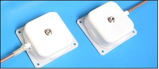
The LDRS transponder secondary payload is intended to demonstrate two-way communications at a low data rate system to support a range of services such as sensor data collection, machine-to-machine communications, and other packet based messaging services. The UHF LDRS antenna is shown in Figure 12.
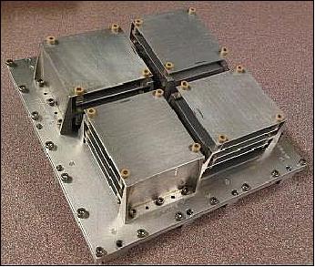
The UHF system collects data from small ground terminals and then downlinks the data using the C-band link. Testing of this system will be performed with the assistance of DRDC-Atlantic and will involve relay of AIS base station data.
The LDRS payload makes use of one of the AIS chains by down-converting the UHF signals from 400 MHz to 162 MHz and then passing it into the AIS NCAP receiver. With this approach, the amount of new hardware is limited and the cost and complexity of the demonstration is kept to a minimum. Currently, the LDRS demonstration is planned to occur during the commissioning phase and then only sporadically for the remainder of the mission.
The Canadian DFO (Department of Fisheries and Oceans) uses buoys equipped with an AIS receiver/transmitter to measure the temperature of the ice in the most northerly regions of the Arctic. Called AtoNs (Aids to Navigation), these buoys are placed directly in the ice. From there, they send the information they collect to an AIS receiver/transmitter on satellites like M3MSat or RCM (RADARSAT Constellation Mission). If successful, this project could provide up-to-the-minute information about ice conditions in the Far North. 22) 23)
DDCM (Dielectric Deep Charge Monitor)
The DDCM is the tertiary payload (Figure 13) and is intended as a technology demonstration, designed and built by DPL Science and sponsored by the CSA. The DDCM will monitor the electrical potential of a dielectric sample due to charging by the space environment. The DDCM data is collected by a payload interface module and then stored in the CDSU. The data is collected as part of the standard housekeeping telemetry and transmitted to the ground over the spacecraft TT&C link. The DDCM is operated continuously when the spacecraft is in nominal operations.
Data from the DDCM instrument will be analyzed and trended for in-orbit flux and material electrical properties. This data will be compared to mathematical predictions and ground-based measurements. The DDCM payload will return information on space weather and material science.
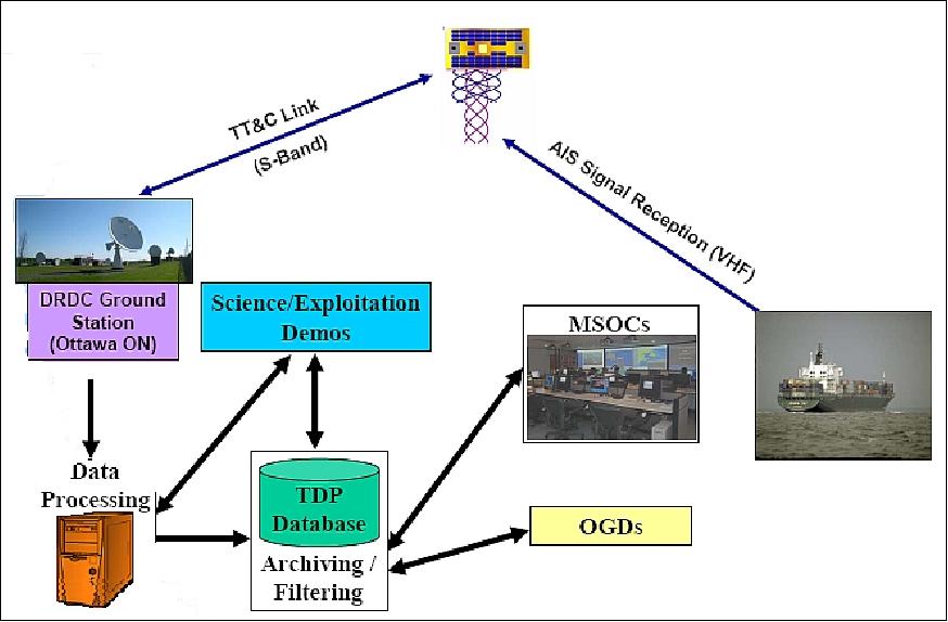
Ground Segment
The M3MSat ground segment architecture is divided into separate functional components: the Science/Payload Operations Centers (SOC/POC), the Mission Planning System (MPS) and MOC. The SOC/POC is the system where the user will send payload activity task requests to the MPS and process the payload data products that come back. 24)
The MPS is the interface between the SOC/POC and the MOC. The MPS evaluates the various payload task requests to produce the payload activity schedule. The MPS also acts as a repository of payload data products and will be made available to the users.
The MOC will be the primary operations center for the lifetime of the mission. For M3MSat, the MOC will be at DRDC Ottawa. The MOC is responsible for commanding and controlling the satellite on-orbit operations by transmitting the payload tasking schedules, originating from the MPS, to the satellite and receiving the payload data products after execution. The MOC coordinates the different resources such as ground station access times, spacecraft pass schedules and spacecraft maintenance operations (Ref. 2).
Note: In 2010, COM DEV International Ltd. has established a subsidiary company, exactEarth Ltd., for the purpose of offering advanced spaceborne AIS-S (Automatic Identification System data Services) to competent maritime authorities around the world. exactEarth will launch its first three AIS microsatellites, which are currently under construction in Canada and Europe, and will begin providing its exactAISTM service within the year.
The DRDC ground segment in support of M3MSat is comprised of a ground station and a MOC (Mission Operations Center). The ground station includes a 9.1m S-band antenna for TT&C (Telemetry, Tracking and Command), a 4.6 m C-band antenna for AIS data download and antenna controllers. The mission planning software, data management system and spacecraft ground terminal are part of the MOC. Although redundancy is present for key systems, adopting the microspace philosophy meant that the ground segment is not as robust as a full operational system could be with multiple levels of back-ups available for each system. Through careful risk mitigation, the system was designed to support the operations of space R&D activities and it has been demonstrated to be ready operationally through regular interactions with the M3MSat flatsat (Ref. 11).
References
1) Donald Bédard, Aaron Spaans, "Responsive Space for the Canadian Forces," AIAA 5th Responsive Space Conference, April 23-26, 2007, Los Angeles, CA, USA, AIAA-RS-5-2007-3004, URL of presentation: https://web.archive.org/web/20150603032623/http://www.responsivespace.com/Papers/RS5/SESSION%20PAPERS/SESSION%203/3004_BEDARD/3004C.pdf
URL of the paper: https://web.archive.org/web/20131213020218/http://www.responsivespace.com/Papers/RS5/SESSION%20PAPERS/SESSION%203/3004_BEDARD/3004P.pdf
2) Siamak Tafazoli, Pascal Tremblay, Alan Hildebrand, "NEOSSat and M3MSat - Two Canadian Microsat Missions," Proceedings of IAC 2011 (62nd International Astronautical Congress), Cape Town, South Africa, Oct. 3-7, 2011, paper: IAC-11-B4.2.9
3) Nathan G. Orr, Jeff Cain, Luke Stras, Robert E. Zee, "Space based AIS detection with the Maritime Monitoring and Messaging Microsatellite," Proceedings of the 4S (Small Satellites Systems and Services) Symposium, Portoroz, Slovenia, June 4-8, 2012
4) "Microsat Systems Canada Inc. (MSCI) formed from the space division of Dynacon Inc.," March 15, 2009, URL: http://www.mscinc.ca/news/2009-03-09-MSCI-Launch.pdf
5) "M3MSat (Maritime Monitoring and Messaging Microsatellite)," URL: https://web.archive.org/web/20230202152515/https://www.utias-sfl.net/?page_id=134
6) "Com Dev wins micro-satellite contract," June 23, 2008, URL: http://www.cbc.ca/technology/story/2008/06/23/comdev-m3msat.html
7) Franz Newland, Elliott Coleshill, Ian Dsouza, Jeff Cain, "Nanosatellite Tracking of Ships — Review of the First Year of Operations," 7th Responsive Space Conference, April 27–30, 2009, Los Angeles, CA, USA, AIAA-RS7-2009-6005
8) Peyman Rahnama, "What are Canada's and Europe's plans and activities relative to greenhouse gas satellite sensing?," NOAA-NASA-EUMETSAT Satellite Hyperspectral Sensor Workshop, March 29-31, 2011, University of Miami, FL, USA, URL: http://www.star.nesdis.noaa.gov/star/documents/meetings/Hyper2011/dayThree/0900Q11-Rahnama.pdf
9) Nathan G. Orr, Jeff Cain, Luke Stras, Robert E. Zee, "Space Based AIS Detection with the Maritime Monitoring and Messaging Microsatellite," Proceedings of the 64th International Astronautical Congress (IAC 2013), Beijing, China, Sept. 23-27, 2013, paper: IAC-13-B4.4.10
10) "Testing Complete on M3M micro-satellite developed by COM DEV," August, 26, 2013, URL: http://www.newswire.ca/en/story/1215301/testing-complete-on-m3m-micro-satellite-developed-by-com-dev
11) Catherine Marchetti, "Experience with the Maritime Monitoring and Messaging Microsatellite (M3MSat)," Proceedings of the 65th International Astronautical Congress (IAC 2014), Toronto, Canada, Sept. 29-Oct. 3, 2014, paper: IAC-14-B4.3.1
12) "Maritime Monitoring and Messaging Micro-Satellite (M3MSat)," CSA, March 4, 2013, URL:
http://www.asc-csa.gc.ca/eng/satellites/m3msat/Default.asp
13) Grant Bonin, Nathan Orr, Robert E. Zee, Jeff Cain, "Solar Array Arcing Mitigation for Polar Low-Earth Orbit Spacecraft," Proceedings of the 24th Annual AIAA/USU Conference on Small Satellites, Logan, UT, USA, Aug. 9-12, 2010, SSC10-X-7, URL: https://utias-sfl.net/wp-content/uploads/SSC10-X-7.pdf
14) "Antennas ship for COMDEV maritime mission," SSTL, June 25, 2010, URL:
https://web.archive.org/web/20150922054937/http://www.sstl.co.uk/Blog/June-2010/Antennas-ship-for-COMDEV-maritime-mission
15) "PSLV-C34 Successfully Launches 20 Satellites in a Single Flight," ISRO, June 22, 2016, URL: http://www.isro.gov.in/update/22-jun-2016/pslv-c34-successfully-launches-20-satellites-single-flight
16) "Maritime Monitoring and Messaging Micro-Satellite (M3MSat)," CSA, April 24, 2015, URL: http://www.asc-csa.gc.ca/eng/satellites/m3msat/
17) "Maritime Monitoring and Messaging Micro-Satellite (M3MSat)," CSA, Oct. 2, 2014, URL: http://www.asc-csa.gc.ca/eng/satellites/m3msat/
18) "The COM DEV International + Antrix Combo For exactEarth's M3M Satellite," Satnews Daily, Oct. 2, 2014, URL: http://www.satnews.com/story.php?number=640703828#
21) W. Chen, T. Jones, A. Macikunas, P. Thomas, E. Choi, "Software Defined Radio (SDR) Payloads for Microsatellite Missions," Proceedings of ASTRO 2010, 15th CASI (Canadian Aeronautics and Space Institute) Conference, Toronto, Canada, May 4-6, 2010
22) Steve Maclean, "Check Against Delivery," Canadian Hydrographic Conference, Niagara Falls, Ontario, May 15, 2012, URL: http://www.asc-csa.gc.ca/eng/media/speeches/2012/0515.asp
23) Benoit Chatelain, Francois Gagnon, Naim Batani, Larry Zakaib, Dung Luong, Phil Thomas, Eric Choi, Basile Agba, Nick Reid, "Design and Applications of a Low Earth Orbit Microsatellite Communication System for Environmental Monitoring," ASTRO'12 , 16th ACSI Astronautics Conference, Québec City, Canada, April 23-26, 2012
24) Xuemin Wang, "Microsatellite M3MSat Ground Systems – Mission Planning System and related VPN and Ground Segment Augmentation," GSAW (Ground System Architectures Workshop) 2013, March 18-21, 2013, Los Angeles, CA, USA, URL: http://sunset.usc.edu/GSAW/gsaw2013/s6/wang.pdf
The information compiled and edited in this article was provided by Herbert J. Kramer from his documentation of: "Observation of the Earth and Its Environment: Survey of Missions and Sensors" (Springer Verlag) as well as many other sources after the publication of the 4th edition in 2002. - Comments and corrections to this article are always welcome for further updates (eoportal@symbios.space).
Overview Spacecraft Launch Sensor Complement Ground Segment References Back to top