JC2Sat-FF (Japan Canada Joint Collaboration Satellites – Formation Flying)
Non-EO
JAXA
Cancelled
CSA
Quick facts
Overview
| Mission type | Non-EO |
| Agency | JAXA, CSA |
| Mission status | Cancelled |
JC2Sat-FF (Japan Canada Joint Collaboration Satellites – Formation Flying)
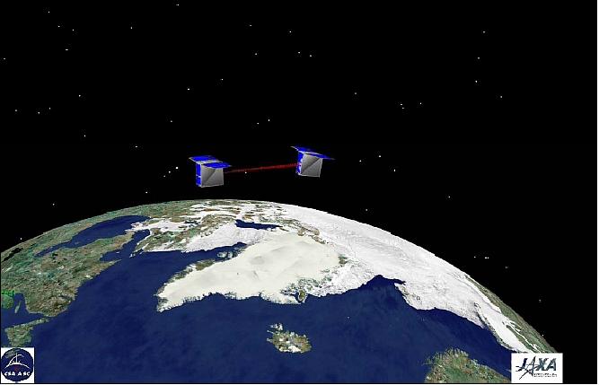
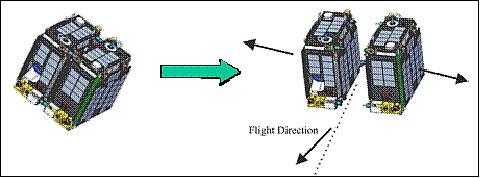
JC2Sat-FF is joint formation flying microsatellite mission of CSA (Canadian Space Agency) and JAXA (Japan Aerospace Exploration Agency). JC2Sat-FF consists of two nearly identical microsatellites, each of ~ 18 kg (they are also referred to as nanosatellites), that are stacked in launch configuration and will be separated using their own intersatellite separation mechanism after separation from the launcher and initial checkout operation.
The JC2Sat-FF project was initiated in October 2006 as a collaboration between CSA and JAXA. The two JC2Sats are designed and built by a team of JAXA and CSA engineers and researchers. Since both agencies have their own internal small satellite projects and have implemented them with different technology and methodology, technical exchange between the two agencies gives stimulation to the members and generates a synergistic effect. 1) 2) 3) 4) 5) 6) 7) 8) 9) 10)
A unique aspect of this project is that the two JC2Sats are being developed by a united small team consisting of engineers and researchers from both agencies. Both agencies have their own internal small satellite projects and have implemented them with different technology and methodology. Technical exchange between the two agencies provides stimulation to the members and generates a synergistic effect.
In this cooperative setup, CSA is responsible for the procurement of manufacturing material and satellite components which are mostly COTS (Commercial-of-the-Shelf) products. Both satellites are being manufactured (S/C structure) and assembled at CSA. I&T (Integration and Test) activities take place in Canada and in Japan. These are conducted at CSA, at the David Florida Laboratory (DFL) in Ottawa, as well as at JAXA. The satellites are designed to be compatible with JAXA's H2A launch vehicle.
The main mission objectives are:
1) To demonstrate the viability of a space technology qualifying system based on microsatellite through the achievement of the following missions:
• AFF (Autonomous Formation Flight) experiment with aerodynamic drag control and GPS based relative navigation
• On-orbit demonstration of a MIRAD (Miniature far Infrared Radiometer) based on an uncooled microbolometer developed with MEMS technology.
2) To research, to implement, and finally, to establish a new streamlined process required to develop small-scale spacecraft with low cost and short delivery time
3) To provide opportunities of hands-on training to CSA and JAXA engineers, and to strengthen the relationship between the two agencies.
The target mission lifetime of JC2Sat-FF is set to be 12 months.
Space Segment
JC2Sat-FF consists of two nearly identical microsatellites. The system architectures of these two satellites are identical. The main difference between the two microsatellites is the size of the two payloads because the optical filters have different focal lengths. The mass of each satellite is about 20 kg, and including the launch separation mechanism, the total mass of JC2Sat-FF is less than 50 kg (2 spacecraft).
A modular tray design (3 stacked trays) is adopted for each spacecraft. The selection of this architecture improves the ease of functional and environmental testing per-module (per tray).
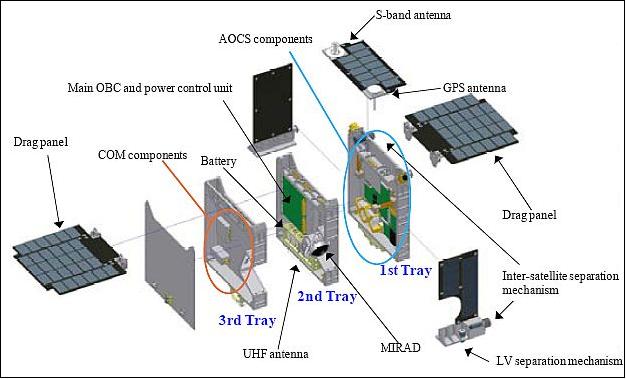
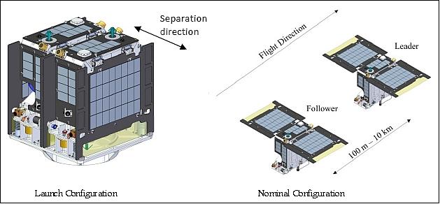
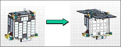
The spacecraft structure is a box of size: 350 mm (W) x 350 mm (D) x 150 mm (H) - excluding the projections of antennas, separation mechanisms, and sensors. The satellites are stacked in launch configuration. After detumbling and initial check-out operations, the satellites will be separated from each other using shape memory based actuators. Attitude acquisition will be performed and finally two drag panels equipped with solar cells will be deployed. JC2Sat-FF system will start its experimental phase in this configuration.
The JC2Sat-FF system includes several mechanisms: the drag panel deployment mechanism, the launch vehicle separation mechanism (LSM) and the ISM (Intersatellite Separation Mechanism). All mechanisms are critical to mission success and this requires high operational reliability.
The nominal attitude control method is momentum biased, nadir pointing three-axis stabilization. A novel feature is that the satellite attitude around the pitch axis is controlled intentionally in order to vary the frontal cross-sectional area of the spacecraft to generate differential aerodynamic drag force instead of using movable drag control panels.
The AOCS (Attitude and Orbit Control Subsystem) uses three magnetic torquers and two momentum wheels as actuators. The attitude is sensed with a 3-axis magnetometer and 2 digital medium sun sensors. The magnetometer and the magnetic torquers are COTS (Commercial off-the-Shelf) components provided by SpaceQuest. The sun sensors represent a Canadian technology developed by Sinclair Interplanetary, utilizing a 1D array to achieve accurate 2D readings of the sun vector. Despite its extremely tiny size, the sun sensor can achieve an accuracy of 0.16º at a full 70º FOV (Field of View). The momentum wheels are also a new Canadian technology developed by Sinclair Interplanetary (a one-man shop in Toronto, Ontario). Unlike traditional reaction wheels, the rotor is not hermetically sealed. One attractive feature of this wheel is its low power consumption (0.5 W at ~0.05 Nms momentum level). First introduction of the new tiny reaction wheels on the CanX-2 nanosatellite of UTIAS/SFL (University of Toronto, Institute for Aerospace Studies/Space Flight Laboratory) with a launch on April 28, 2008.
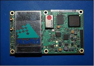
A GPS receiver (NovAtel OEM4-G2L) provides on-board position data which is being used for for orbit determination and real time single point positioning results - without the use of any computational resources in the mission computer. This is a high performance dual frequency (L1/L2) commercial receiver used widely in land surveying instruments. - For the mission, the receiver firmware has been modified to remove altitude and speed restrictions, and the internal tropospheric correction is forced to zero. A major advantage of the receiver is the small size (100 mm x 60 mm x 16 mm), low power consumption (1.6 W), and low mass (56 g).
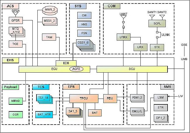
Each satellite will have two flight computers: IFC-1000 from SpaceQuest, which is based on a V53 processor, handles the key I/O and the telemetry of the spacecraft. The principle advantage of this system is low power consumption (< 200 mW) and long flight heritage with no single failure. The second computer, which is based on an ARM processor, is provided by UTIAS (University of Toronto Institute of Aerospace Studies). This flight computer has more computing power and will be used to handle AOCS, the ISL (Intersatellite Link) and the payload controller.
The TCS (Thermal Control Subsystem) is required to maintain on-orbit spacecraft temperatures within the limits defined by equipment operating conditions, based on the worst-case predicted in-orbit temperatures, over the lifetime of the mission.
Spacecraft mass | each ~ 18 kg, total mass < 50 kg (both S/C including launch separation mechanism) |
Spacecraft size | each ~ 35 cm x 35 cm x 15 cm |
Power | > 14 W (average) |
Attitude | 3-axis stabilization (controlled momentum-biased) |
RF communications | Uplink: 9.6 kbit/s (UHF), |
Mission life | 1 year (target) |
RF communications: The communications subsystem is based on a UHF uplink and S-band downlink for the payload data. The ISL data transfer uses the UHF-band.
Launch
As of 2013, the launch of the JC2Sat-FF project “is on hold indefinitely”. 11)
Orbit: Sun-synchronous orbit, altitude ~ 700 km, inclination = 98.19º, LTAN (Local Time on Ascending Node) at 13:30 hours
Sensor/experiment complement: (ISM, AFF, MIRAD, LRA)
ISM (Intersatellite Separation Mechanism) Experiment
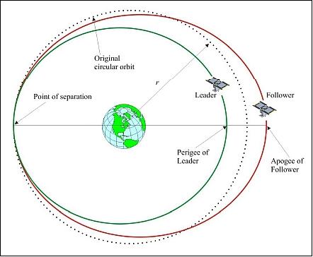
The requirements call for: a) a collision-free separation; b) low drift rate; c) minimum oscillations in the along-track and radial directions; d) and a reduction of secular drift in the cross-track direction.
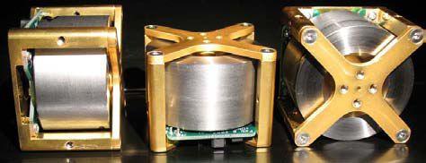
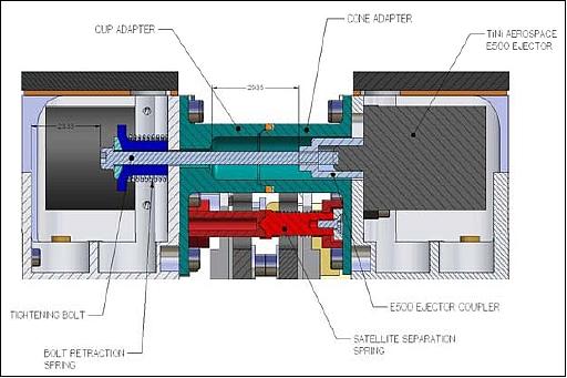
In the stacked configuration, the satellites are held together by four ISMs (Figure 7). Each ISM is joined or separated at a cup/cone adapter. The side holding the cone also houses an ERM (Ejector Release Mechanism). As such, the satellite holding the cone also has to provide the necessary electrical current for activation. The key design requirements for the ISM are: (Ref. 1)
1) withstand the launch load
2) impart a separation speed Vo < 2 cm/s on each satellite.
To reduce the separation speed, it is planned that the 4 ISM be activated in two sequences. In the first sequence, two ISM in two diagonal corners are released. Then, moments later, the other two ISM will be activated. Separation will be detected by a micro-switch located adjacent to the ISM. Each satellite is designed to provide current for two ISM release.
The key of the ISM is the ERM, which is an electronically-triggered Titanium-Nickel based shape memory alloy (SMA) device manufactured by TiNi Aerospace (part number ERM–500). Each ERM has a mass of 74 g and can be activated and reset up to 50 times. Further, it has a built-in redundant firing circuit that ensures successful release. Prior to launch, the satellites are rigidly attached at the ISM’s cup/cone adapters by applying sufficient tension to the tightening bolt, which is coupled from one satellite to the ERM on the opposing satellite. There are 4 springs in each ISM: ejector spring (E) is a component residing inside the ERM, bolt retraction spring (BR) functions to ensure full retraction of the ERM after activation, separation spring (SS) ensures the separation of the cup/cone coupler and micro-switch (MS) spring that detects successful separation. 12)
The following steps describe the sequence of events in the separation process:
• When the ERM receives an appropriate voltage input, it releases the coupler loaded by E spring.
• The coupler is attached to the tightening bolt which is also pulled away from the ERM by the BR spring located on the other satellite.
• The motion of the coupler leaving one satellite body and colliding with the other causes the two satellites to move in opposing directions.
• An additional separation force is applied to each satellite by the separation spring, and micro-switch.
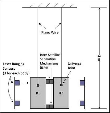
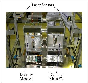
ISM experiment: To validate the performance of the ISM, JAXA built a test setup in the Tsukuba Space Center. Figure 8 shows the schematics of the test setup. Two 17 kg satellite dummy-masses were individually suspended by piano wires. As the planned separation scenario will fire only two ISM at a time, only two ERM are installed inside two ISM. The position at three different locations of each body were measured using laser ranging sensors (Figure 9). The individual measurements can be used to estimate the angular rotation, or tip-off rate, as well as the translational speed, which is calculated as the slope of the average of the three position measurements over time. In addition, a high speed camera was used to observe the separation at the ISM. This information provides a qualitative understanding of the separation mechanics.
Test results: In the JC2Sat project, the ISM speed is critical for the success of formation flying demonstration. This requires a specially designed separation mechanism. The test results indicate that despite the best effort in designing the ISM, the separation requirement cannot be met. As such, a soft release mechanism is planned to be added to the current JC2Sat baseline.
AFF (Autonomous Formation Flight) Experiment
The primary mission of JC2Sat-FF is to demonstrate spacecraft FF technology using aerodynamic drag control by varying the cross-sectional area of the spacecraft, and GPS-based relative navigation. The principle advantage of this concept is the absence of a propulsion system, which reduces the complexity and cost of the spacecraft design. 13)
The breadth of formation-flying maneuvers achievable by JC2Sat is limited by the magnitude and direction of the differential drag forces which are small, owing to the extremely low atmospheric density in LEO, and applicable only in the direction opposite to the velocity. Despite these limitations, previous studies have shown that formation keeping and a range of formation maneuvers can be achieved using differential drag.
Given the low control authority of aerodynamic drag at orbital altitudes, the most critical element of the mission is to ensure that, compared to other environmental perturbations, there is enough controllability to acquire the formation and to maintain it. Formation acquisition is further decomposed into the need to stop the initial in-plane drift caused by the separation impulse (control of the semimajor axis) and reduce the in-plane football-orbit relative oscillations to within a mission-acceptable relative distance (eccentricity control). Out-of-plane drift remains uncontrolled and will essentially determine the mission life, foreseen to be of the order of 12 months.
The commercial dual-frequency (L1/L2) GPS receiver OEM4-G2L of NovAtel is being used with several modifications on its firmware. The attractive physical features of the receiver are small size (100 mm x 60 mm x 16 mm), low power consumption (1.6W) and mass (56g). These features make the receiver of particular interest for small satellite mission with tight onboard resources. 14)
The autonomous formation keeping essentially consists of the following steps:
1) The GPS measurements for each microsatellite are obtained by its respective GPS receiver
2) The follower microsatellite then transmits this information via an RF intersatellite link (ISL) to the leader microsatellite
3) The AOCS software of the leader microsatellite will then compute the separation between the microsatellites and determine the needed control authority for each microsatellite to maintain the baseline
4) The leader microsatellite then transmits this information to the follower microsatellite
5) The control authority is achieved by changing the pitch angle of each satellite, which results in the required change in differential aerodynamic drag.
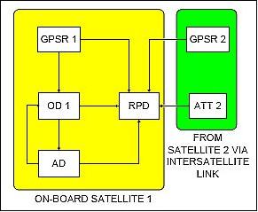
Legend to Figure 11: GPSR = GPS Receiver, OD = Orbit Determination, RPD = Relative Position Determination, AD = Attitude Determination, ATT = Attitude.
Figure 11 shows the flow of information between the different algorithms. Due to the fact that the AOCS on each satellite requires orbital information, both satellites perform orbit determination, and the orbit determination algorithms are identical for both satellites. The relative position determination occurs only on one of the satellites, which makes the formation control decisions.
Since the GPS antennas are offset from the satellite centers of mass, both the attitude and GPS measurements are needed in the orbit determination algorithm. The relative positioning algorithm requires the GPS measurements and attitudes of both satellites. It also requires the orbital information of one of the satellites.
Background: The concept of spacecraft formation keeping using drag panels was first proposed by Carolina L. Leonard in 1987 (thesis at MIT). In her paper, Leonard discussed the feasibility of using differential drag panels as a means of formation keeping of spacecraft formations for low altitude orbits and showed that formation keeping with differential drag is possible. There are many advantages of using differential drag as an actuation means for formation keeping and they are: 15) 16)
• Mass and volume savings due to the absence of a conventional propulsion system
• No contamination from propellant exhaust; ideal for missions that have highly sensitive onboard sensors
• The relative acceleration generated is very small and so there is no shock generated; ideal for missions that have sensors that are very sensitive to shock and vibrations.
The drawbacks of such a system are:
• The cross-track drift is difficult to control
• Relative positions cannot be controlled to a very high accuracy and in a given frame of time
• Mathematical modeling of motion is difficult due to numerous unpredictable time varying factors
• A means to vary the frontal cross-sectional area is needed.
Given the limitations of the system, the differential drag technology is ideal for small satellite FF missions that have coarse control accuracy requirements.
MIRAD (Miniature far Infrared Radiometer)
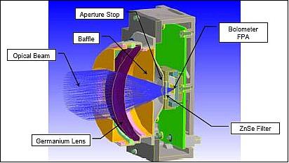
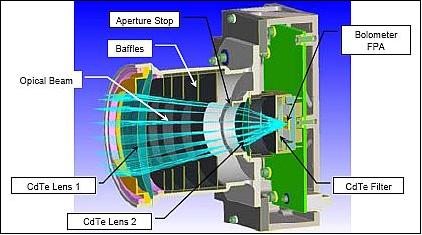
A further mission objective is to demonstrate the novel uncooled microbolometer technology (MIRAD) developed in Canada. CSA and INO (Institute National d’Optique) of Ste-Foy, Quebec have jointly developed a new generation of uncooled microbolometer detectors that are capable of FIR (Far Infrared) sensing (i.e. in the 15 µm spectral range and > 15 µm).
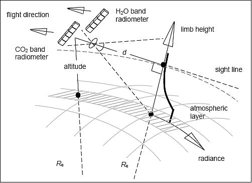
Spaceborne measurements in the FIR region are generally not being performed on a routine basis due to the lack of detectors with adequate capability beyond the 15 µm spectral range. The purpose of the two MIRAD instruments in the JC2Sat mission is to co-register the Earth’s limb profiles with global and seasonal variations in the emission bands of greenhouse gases CO2 and H2O, centered respectively at wavelengths of 15 µm and 25 µm (Figures 13 and 14).
While each microsatellite will fly a MIRAD instrument, the optical filter on each MIRAD will be different. FIR1 is designed to measure the radiance in the CO2 band at 15 µm. FIR2 is designed to measure the radiance of H2O in the 25.2 µm band. Each MIRAD device will co-register its limb radiances as the microsatellites fly in formation. Possible science products will be the temperature profile and the mixing ratio of H2O.
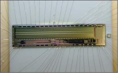
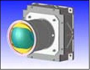
The two MIRAD units have been designed to be compatible with the microsatellite allocated budgets: an average power consumption of 500 mW, a mass of 0.5 kg, and an envelope of 100 mm x 105 mm x 105 mm.
Each MIRAD unit will be mounted at the rear of a microsatellite and backward staring at the Earth's limb behind the satellite. An advantage of this configuration is that each unit is allowed to view the cold space to perform calibration each time the satellite pitches down.
To perform co-registration, the limb radiance is measured successively by each unit when the latter is at a given distance from the tangent point. Each unit starts acquiring data when turned on and stops when powered down by the spacecraft computer. The focal plane array operates in the staring mode at a frame rate of 10 Hz, and the time required to make one measurement is the time required to acquire and average out a predetermined number of frames. During a sequence of measurements, a latitude portion is covered and this sequence is repeated periodically until full latitude coverage is achieved.
In conclusion, the microsatellite formation allows for distribution of multiple MIRAD instruments measuring at different wavelengths which would traditionally require a large single spacecraft. Once demonstrated in space MiIRAD will open up opportunities for future low-cost formation flight Earth observation missions.
LRA (Laser Reflector Assembly)
Information will be provided at a later time.
JC2Sat Operations Scenario
Spacecraft operations will be performed mainly from two ground stations located in Canada and Japan. The JC2Sat mission duration is defined to be one year and split up into four phases:
• Phase I: Stacked Phase - 1/2 month
Once released in orbit the satellite stack will be de-tumbled into a so-called Power Positive Parking (P3) mode, using the attitude control system of only one of the two satellites. While in P3 attitude, power generation is sufficient to allow for a proper checkout of the bus and MIRAD payload of each spacecraft. 17)
Finally the stack will be given the Inter-satellite Separation Pointing (ISP) attitude and after activation of the individual navigation system (GPS) on each satellite the satellites will be separated by activating the Inter-satellite Separation Mechanisms (ISMs) at a specific point in the orbit when the separation direction is at a 10º angle with the orbit normal.
• Phase II: Preparation Phase - 1/2 month
During the preparation phase, the drag panels will be deployed. To ensure that the satellites will not drift apart too far before AFC (Autonomous Formation Control) will be activated; the Follower spacecraft is given a pitch command directly from the ground which will start drift reduction. Afterward the ISL (Inter-Satellite Link) and RNS (Relative Navigation System) will be activated and checked out (Ref. 14). The AFC will then be activated to bring the drift autonomously to a stop.
• Phase III: AFF (Autonomous Formation Flight) Phase - 5 months
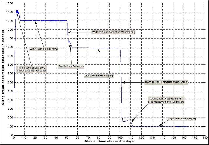
During this phase, AFC is exercised by performing “formation keeping” at a distance between 1 and 5 km (wide formation), 1 km (close formation), and 100 m (tight formation) and performing formation maneuvering between these distances. A separation accuracy of 1% (with a minimum of 10 m) of the separation distance is targeted. During this AFF phase random MIRAD data collection will take place.
• Phase IV: MIRAD Phase - 6 months
During the last phase of the mission, priority is given to the collection of MIRAD data. To acquire a complete set of scientific MIRAD data within 30 days, both MIRAD instruments need to make one sequence of measurements (~14 s total) per orbital period (~100 min) at a predefined location per orbit. As such, both satellites need to be kept at an un-pitched attitude, i.e. AFC needs to be interrupted, for the very short duration of this measurement. As this interrupted period is extremely short compared to the control cycle of the formation control, the effect on the accuracy of the constant distance between the two satellites will be negligible.
References
1) Alfred Ng, Casey Lambert, Keiichi Hirako, Hiroshi Horiguchi, Yosuke Nakamura, “Japan Canada Joint Collaboration Satellites – Design of Intersatellite Separation Mechanism,” Proceedings of the 61st IAC (International Astronautical Congress), Prague, Czech Republic, Sept. 27-Oct. 1, 2010, IAC-10-B4.6B.6
2) Keisuke Yoshihara, Marleen van Mierlo, Alfred Ng, Balaji Shankar Kumar, Anton De Ruiter , Yutaka Komatsu, Hiroshi Horiguchi, Hidekazu Hashimoto, “JC2Sat-FF: An International Collaboration Nano-Sat Project Overview of the Project, System Analyses and Design,” Proceedings of the IAA Symposium on Small Satellite Systems and Services (4S), Rhodes, Greece, May 26-30, 2008, ESA SP-660, August 2008
3) Alfred Ng, M. van Mierlo, K. Yoshihara, H. Horiguchi, H. Hashimoto, “JC2Sat: A Unique International Collaboration,” Proceedings of ASTRO 2008 - 14th CASI Canadian Astronautics Conference, Montreal, Canada, April 29 - May 1, 2008
4) H. Horiguchi, K. Hirako,H. Hashimoto, “Small Satellites Development Program in JAXA,” Proceedings of ASTRO 2008 - 14th CASI Canadian Astronautics Conference, Montreal, Canada, April 29 - May 1, 2008
5) Balaji Shankar Kumar, Alfred Ng, Keisuke Yoshihara, “Flight Dynamics and Control of the JC2SAT-FF Mission,” Proceedings of the AAS/AIAA Astrodynamics Specialist Conference, Mackinac Island, MI, USA, Aug 20-24, 2007, AAS 07-410
6) Anton de Ruiter, James Lee, Alfred Ng, “A Fault- Tolerant Magnetic Spin Stabilizing Controller for the JC2Sat- FF Mission,” AIAA Guidance, Navigation and Control Conference and Exhibit, 18 - 21 August 18-21, 2008, Honolulu, HI, USA, AIAA-2008-7486
7) Alfred Ng, Linh Ngo Phong, Keisuke Yoshihara, François Châteauneuf, “JC2Sat & MIRAD: A unique nanosatellite with a unique EO payload,” Proceedings of the 59th IAC (International Astronautical Congress), Glasgow, Scotland, UK, Sept. 29 to Oct. 3, 2008, IAC-08-B4.2.02
8) Marleen van Mierlo, Keisuke Yoshihara, Alfred Ng, Linh Ngo Phong, François Châteauneuf, “Earth Observation using Japanese/Canadian Formation Flying Nanosatellites,” Proceedings of the 7th IAA Symposium on Small Satellites for Earth Observation, Berlin, Germany, May 4-7, 2009, IAA-B7-1101, URL of presentation: http://media.dlr.de:8080/erez4/erez?cmd=get&src=os/IAA/archiv7/Presentations/1101%5FIAA%2DB7%2D1101%5FJC2Sat%5FMvMierlo.pdf
9) Jean de Lafontaine, Jean-François Hamel, Alfred Ng, Casey Lambert, Marleen van Mierlo, Keiichi Hirako, Hiroshi Horiguchi, Keisuke Yoshihara, “Japan Canada Joint Collaboration Satellites - Formation Flight (JC2Sat-FF) Design & Analysis,” Proceedings of the Symposium on Small Satellite Systems and Services (4S), Funchal, Madeira, Portugal, May 31-June 4, 2010
10) Alfred Ng, Philippe Vincent, Balaji Shankar, Keiichi Hirako, Hiroshi Horiguchi, Keisuke Yoshihara, “An Update on the Japan Canada Joint Collaboration Satellites (JC2Sat),” Proceedings of ASTRO 2010, 15th CASI (Canadian Aeronautics and Space Institute) Conference, Toronto, Canada, May 4-6, 2010
11) Information provided by Alfred Ng of CSA (Canadian Space Agency), Saint-Hubert, Quebec, Canada.
12) Casey Lambert, Philippe Vincent, Hiroshi Horiguchi, Yosuke Nakamura, “Inter-Satellite Separation Dynamics for the JC2Sat Formation Flying Mission,” Proceedings of ASTRO 2010, 15th CASI (Canadian Aeronautics and Space Institue) Conference, Toronto, Canada, May 4-6, 2010
13) Anton de Ruiter, James Lee, Alfred Ng, Yuri Kim, “Orbit Determination & Relative Positioning Techniques for JC2Sat-FF,” Proceedings of the 3rd International Symposium on Formation Flying, Missions and Technology, ESA/ESTEC, Noordwijk, The Netherlands, April 23-25, 2008, ESA SP-654, June 2008
14) Keisuke Yoshihara, Toru Yamamoto, Yoshinori Kondoh, Hidekazu Hashimoto, Alfred Ng,, Anton de Ruiter, James Lee, “Performance Assessment of Single and Dual Frequency, Commercial-Based GPS Receivers for LEO Orbit,” SSC07-X-5, Proceedings of the 21st Annual AIAA/USU Conference on Small Satellites, Logan, Utah, USA, August 13-16 2007
15) Carolina L. Leonard, W. M. Hollister, E. V. Bergmann, “Orbital Formation-Keeping with Differential Drag”, AIAA Journal of Guidance, Control, and Dynamics, Vol. 12, No. 1. Jan.– Feb. 1989, pp. 108-113
16) Balaji Shankar Kumar, Alfred Ng, Keisuke Yoshihara, Anton De Ruiter, “Differential Drag as a Means of Spacecraft Formation Control,” Proceedings of the 2007 IEEE Aerospace Conference, Big Sky, MT, March 3-10, 2007
17) Anton de Ruiter, Marleen van Mierlo, James Lee, Sudarshan Martins, Alfred Ng, Keisuke Yoshihara, “A Power Positive Parking Attitude Mode with a Fault-Tolerant Magnetic Spin Stabilizing Controller for the JC2Sat Mission,” Proceedings of the 27th ISTS (International Symposium on Space Technology and Science) , Tsukuba, Japan, July 5-12, 2009, paper: 2009-d-08
The information compiled and edited in this article was provided by Herbert J. Kramer from his documentation of: ”Observation of the Earth and Its Environment: Survey of Missions and Sensors” (Springer Verlag) as well as many other sources after the publication of the 4th edition in 2002. - Comments and corrections to this article are always welcome for further updates (eoportal@symbios.space).