ISS: WORF (Window Observational Research Facility)
EO
NASA
High resolution optical imagers
Land
Quick facts
Overview
| Mission type | EO |
| Agency | NASA |
| Mission status | Operational (nominal) |
| Launch date | 04 May 2010 |
| Measurement domain | Land |
| Measurement category | Multi-purpose imagery (land) |
| Measurement detailed | Land surface imagery |
| Instrument type | High resolution optical imagers, Hyperspectral imagers |
| CEOS EO Handbook | See ISS: WORF (Window Observational Research Facility) summary |
ISS utilization: WORF (Window Observational Research Facility) / ISAAC, ISERV
WORF Layout ISSAC ISSAC Launch ISERV ISERV Launch References
WORF is a NASA payload rack facility which was flown to the ISS on the STS-131 mission (April 5-18, 2010) and installed into the US Destiny Laboratory.
WORF provides a new capability for scientific and commercial payloads and will be a resource for public outreach and educational opportunities for Earth sciences (e.g., the EarthKAM, etc.). The WORF rack is located inside the Earth-facing side of the US Destiny laboratory module. 1) 2) 3) 4)
WORF is a rack system surrounding the Lab window for attaching sensors (cameras, multispectral scanners, and other instruments). It provides attachment points, power and data transfer capability for instruments to be mounted in the window. Multiple instruments can be mounted at the same time. The rack is designed to allow rapid changes of equipment by the crew. 5) 6)
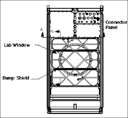
Laboratory Window
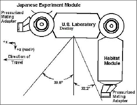
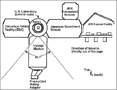
The nadir window on the Destiny Lab features the highest quality optics and allows viewing of 39.6º forward along the axis of the station, 32.2º aft, and 79.1º from the port to starboard.
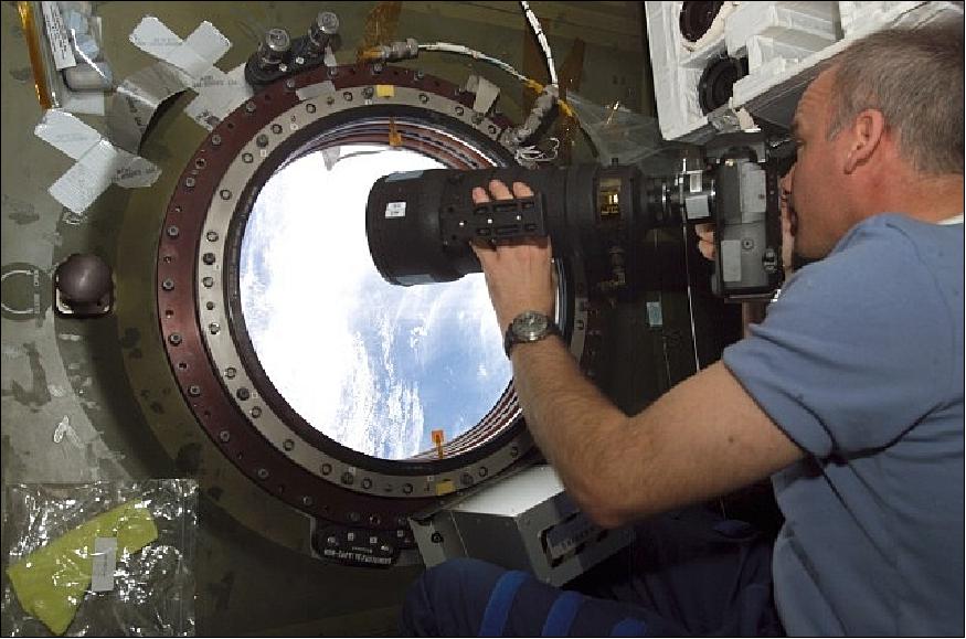
Legend to Figure 4: NASA Image: ISS013E07988 - Jeff Williams, Expedition 13 Science Officer, at the U.S. Laboratory Science Window on the ISS.
The Lab window itself is 50.8 cm in diameter. The window is made up of an assembly of four separate panes (Figure 5). The outermost pane is a replaceable debris pane a little more than 1.0 cm thick. It is designed to protect the window from small orbital debris or micrometeoroids that might strike the station. If it is severely damaged, it can be replaced during an EVA. The two middle panes serve as the primary and secondary pressure windows, ensuring that the laboratory module stays pressurized. Each of these panes is ~3.2 cm thick.
The innermost pane, a multi-layer scratch pane, is a little less than a 1.7 cm thick. The scratch pane has an integral heater element to prevent condensation from forming on the pressure panes, and has a special anti-scratch coating that protects against accidental bumps from camera lenses and other equipment during set-up work inside the WORF rack. Although the scratch pane can support normal photography, it is often necessary to remove the scratch pane during the operation of other high-resolution sensors.
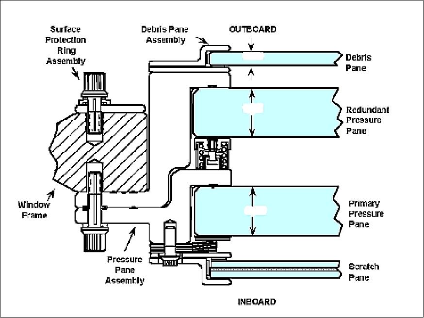
When the scratch pane is removed, the WORF provides a deployable metal and acrylic bump shield to protect the primary pressure panes while equipment is set up in front of the window. When the sensors are ready for use and the interior of the WORF rack has been secured with a hatch cover, the bump shield can be retracted using controls on the outside of the WORF rack, giving the cameras/sensors a clear view through the window to the Earth below. When the scratch pane (and its heater element) is removed, the WORF rack provides a variable air flow across the window to prevent condensation.
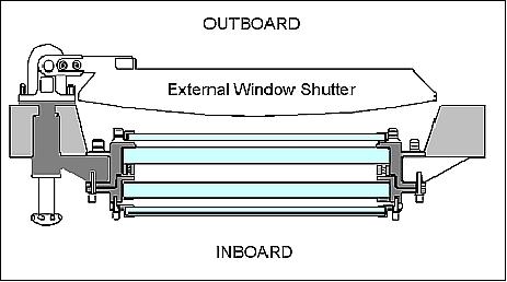
When the WORF is not in use, when visiting spacecraft are docking with the ISS, or when the window is exposed to orbital ram conditions during special orientations of the ISS, the research lab window is protected by a metal cover on the outside of the Destiny lab module. This external window shutter pivots on hinges and is rotated open and closed by the crew using controls on the WORF rack.
The WORF has allowed astronauts to permanently remove a protective, non-optical "scratch pane" on the window, which had often blurred images. The WORF also provides a highly stable mounting platform to hold cameras and sensors steady, while offering power, command, data, and cooling connections. With the WORF, the high-quality optics of the nadir viewing window—looking "straight down" towards the Earth—are now fully utilized for the first time since Destiny was launched in 2001 (Ref. 4).
WORF Layout
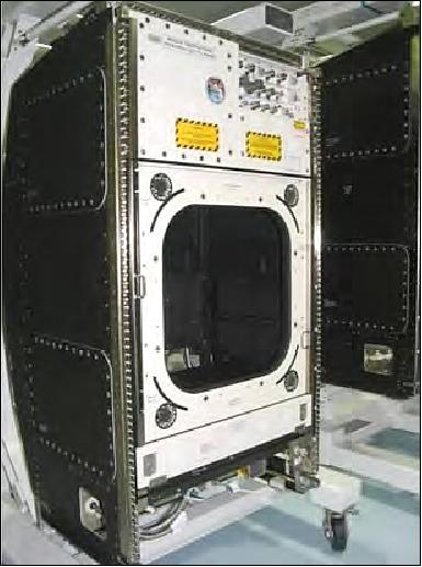
WORF is based on an ISPR (International Standard Payload Rack) element and utilizes avionics and hardware adapted from the EXPRESS (EXpedite the PRocessing of Experiments to Space Station) Rack program. The rack provides a payload volume equivalent to 0.8 m3, and is able to support up to three payloads simultaneously, depending on available resources and space available at the window.
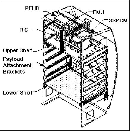
The WORF rack hardware includes:
- RIC (Rack Interface Controller)
- Command and control interface for rack subsystems
- PEHB (Payload Ethernet Hub/Bridge)
- Ethernet interface to payloads
- EMU (EXPRESS Memory Unit)
- Solid state memory device (320 MB) used for system software files, and configuration files
- SSPCM (Solid State Power Controller Module) which provides 120 VDC output to the RIC, AAA fan, PEHB, and Area Smoke Detector, and which converts 120 VDC to 28 VDC for payloads.
WORF Window Features
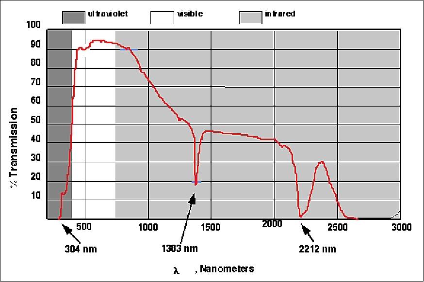
The spectral properties of the Lab window support remote sensing work. The reflective coating on the window absorbs UV radiation, but transmittance rises rapidly after 304 nm to > 90% in the visible and into the near infrared. Transmittance tails off after 800 nm, reaching zero at approximately 2600 nm (Figure 9).
Corning Inc., Corning, N.Y., provided the glass capable of supporting viewing with high-resolution telescopes. The glass panes were polished to a fine finish by Zygo Corp., Middlefield, Conn. The panes were coated by Optical Coating Lab Inc., Santa Rosa, CA, with anti-reflection chemicals that block ultra-violet radiation from the sun. The coating also is electro-conductive to cut down on condensation. The glass is homogenous, free of color; it has been polished very smoothly and is flat. In addition, for extra protection, the outermost panel has a clamshell-like protective aluminum cover that can be closed from inside the station.
Instruments onboard the ISS utilizing the WORF (ISSAC, ISERV)
The initial NASA ISS sensor systems available to respond to IDC (International Disaster Charter) activations included ISSAC (ISS Agricultural Camera). The ISSAC completed its primary mission and was removed from the WORF (Window Observational Research Facility) in the US Destiny Laboratory Module in January 2013. The ISSAC was replaced by the very high resolution ISS SERVIR Environmental Research and Visualization System (ISERV) Pathfinder, also installed in the WORF. The ISERV completed its primary mission in December 2014, but remains in stowage on the ISS for potential future use (Ref. 23).
ISSAC (International Space Station Agricultural Camera)
ISSAC is a multispectral camera designed and developed by students and faculty at the University of North Dakota (UND), Grand Forks, ND. The objective of the imager is to observe Earth from aboard the ISS using the WORF facility. The data will is targeted directly to the needs of agricultural users in the northern Great Plains (of USA). The ISSAC project was initiated in 2001 under the name of "AgCam (Agricultural Camera)." But UND changed the name of the instrument in May 2010 following notice from a North Dakota company, Dakota Micro Inc., that it had registered a claim on the name. 7) 8) 9)
ISSAC is designed to take frequent images, in visible and infrared light, of vegetated areas on the Earth, principally of growing crops, rangeland, grasslands, forests, and wetlands in the northern Great Plains and Rocky Mountain regions of the United States. Images will be delivered within two days directly to requesting farmers, ranchers, foresters, natural resource managers and tribal officials to help improve their environmental stewardship of the land. Images will also be shared with educators for classroom use.
The NASA Office of Education is sponsoring the ISSAC instrument for launch and on-orbit operations aboard the ISS. 10) 11) 12)
Instrument
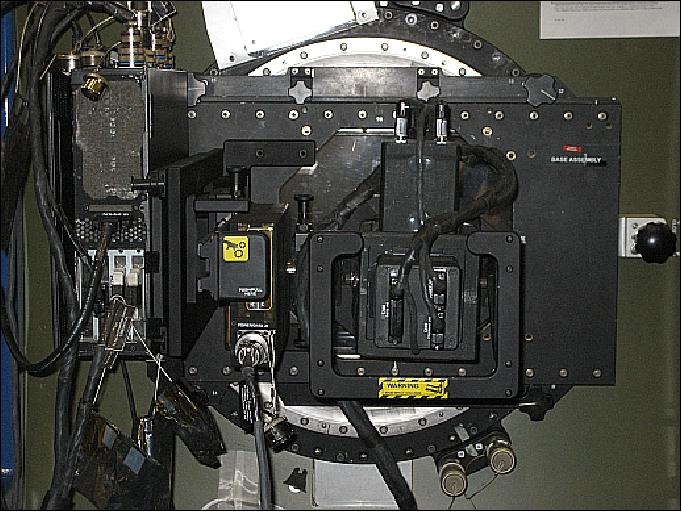
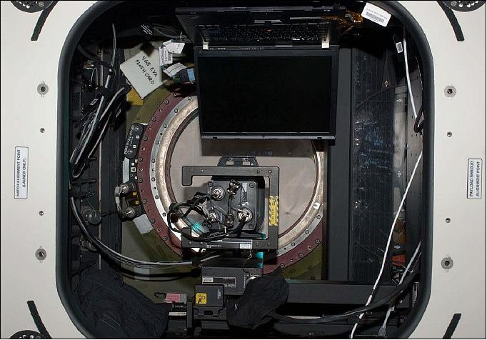
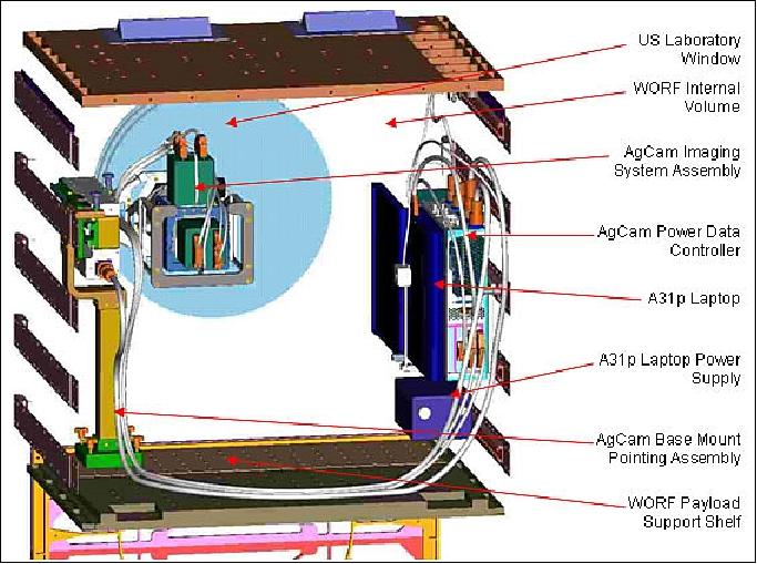
The primary ISSAC system components include an ISA (Imaging System Assembly), a BMPA (Base Mont Pointing Assembly), a power/data controller, associated cabling and support items, and a NASA-supplied Laptop and power supply. 13)
Within ISA, an isolation mount uses a tuned passive visco-elastic system to provide the vibration isolation and absorption needed to prevent excessive jitter in the ISSAC imagery. The electro-optical sensor of ISSAC was designed and built by Fluxdata Corp. of Rochester NY. The instrument optics includes 3 COTS 12- bit firewire cameras (Basler, with Sony CCD) and 3-way prism beamsplitter with trim filters. The bandpasses were specified to coincide with comparable Landsat bandpasses (Ref. 7):
- 515-600 nm (green)
- 630-700 nm (red)
- 740-910 nm (NIR)
The lens is a modified COTS (Sigma f/2.8 APO EX-DG Macro HSM) device, mounted (via Nikon f-mount) on to ISA (ISSAC Sensor Assembly), whose components include the sensor optics, sensor backplate (with internal Firewire hub), and interconnecting Firewire and Trigger cables. The ISA, in its on-orbit configuration – mated to the ISSAC lens, mounted into the vibration isolating sensor frame, and with attached sensor cables (Figure 10).
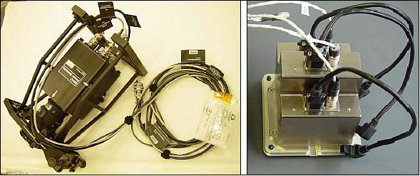
Figure 11 illustrates in functional schematic form the remaining ISSAC components integrated together with the WORF. The ISA is represented by the Lens, Beamsplitter (BS), three cameras (C1, C2, C3), Firewire hub, and GPIO board.
The ISA, mounted within its sensor frame, attaches to a mechanical cam interface on the SPA (Slide Pointing Assembly). The SPA utilizes a closed loop PCS (Pointing Control System) to orient the ISA up to 30º in the cross-track direction in response to ground commands. The PCS, which is based on COTS (MicroMo Inc.) components (brushless servomotor, optical encoder, MVP2001A01 controller electronics), can be controlled to one thousandth of a degree. Controller parametric specifications, acceleration profiles and duty cycles were selected to minimize both transit and settling time in the microgravity environment.
The SPA and the ISA are both powered by the ISSAC PDC (Power/Data Controller). Internal to the PDC, a PCB (Power Control Board ) receives and isolates incoming 28 VDC power from the WORF, and supplies conditioned 28 VDC and 12 VDC power to ISSAC subsystems. A custom DAC (Data Acquisition Card) acquires temperature, current, and logic state values from sensors and supplies resultant data to the ISSAC laptop via a parallel port interface. Integral fans maintain thermal cooling in the microgravity environment.
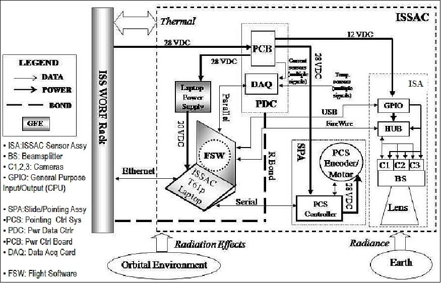
The ISSAC FSW (Flight Software) is resident on a NASA-supplied space-qualified IBM t61p laptop computer, installed by the crew from a DVD binary image. Running under Windows XP, the FSW receives commands and transmits telemetry data over Ethernet communication with the WORF (TCP/IP), and controls and interacts with the ISA using USB2 and Firewire (IEEE 1394a), with the SPA using serial port (RS-232) communications, and with the PDC using parallel port communications.
Healthy vegetation is highly absorptive in the red band (R), and highly reflective in the near-infrared band (NIR); combining them via ground data processing into a NDVI (Normalized Difference Vegetation Index), where NDVI = (NIR-R) / (NIR+R), yields an indicator that is highly responsive to reductions in plant health, whether from reduced chlorophyll production (increases R reflectance) or from heat/drought stress-induced stomata closure (decreases NIR reflectance).
Launch
The ISSAC instrumentation was launched aboard the JAXA HTV-2 (H-II Transfer Vehicle-2) on January 22,2011 from TNSC (Tanegashima Space Center). The unmanned cargo spacecraft arrived at the ISS on January 27, 2011. HTV-2 was nicknamed Kounotori 2 (White Stork). 14) 15)
Initial ISSAC components (then referred to as AgCam) were launched to the ISS onboard STS-126 Endeavour (cargo designation of Utility Logistics Flight (ULF)-2) in November 2009, with additional components flown up on the Japanese HTV-2 ELV in January, 2011.
Operational Requirements - ISSAC
To be able to image the Earth, AgCam/ISSAC requires the ISS to be in Local-Vertical-Local-Horizontal (LVLH) orientation, and requires the US Laboratory Window external shutter to be open. Typically, imaging operations will occur only when the ISS is over the northern central region of the United States, though imagery can be collected throughout all ISS orbits whenever the Earth surface below is in daylight. Frequency and location of imaging will be highly dynamic, driven by needs of a wide variety of end user research partners, but will be much more extensive during the growing season of the northern plains (April - October). At peak times, 2-4 images per orbit for 4 consecutive orbits are anticipated; several hours of powered operations immediately following collection will be required to complete image downlink.
Operational protocols: Crew members install AgCam components, including an A31p Laptop and other GFE equipment, into the internal volume of the WORF. Once setup and activation of AgCam is complete, no more crew support is needed for nominal operations, other than manual opening and closing of the Lab Window external shutter per standard flight rules. From within the AgCam Science Operations Center at the University of North Dakota, operators will receive AgCam imagery requests from an extensive network of end-user research participants, and will convert these requests into specific sets of commands for uplink to AgCam. Through coordination with NASA for WORF rack operations, image acquisition and other AgCam operational commands will be uplinked to the AgCam payload software, which will take images over specific areas of the Earth. Resultant imagery data will be downlinked and transferred to the University of North Dakota for processing and quick delivery to image requestors.
Mission Status - ISSAC
• The ISERV completed its primary mission in December 2014, but remains in stowage on the ISS for potential future use (Ref. 23).
• In 2012, the ISSAC system continues to function nominally. — ISSAC takes frequent visible-light & infrared images of vegetated areas on the Earth. The camera focuses principally on rangelands, grasslands, forests, and wetlands in the northern Great Plains and Rocky Mountain regions of the United States. The images may be delivered directly upon request to farmers, ranchers, foresters, natural resource managers and tribal officials to help improve their environmental stewardship of the land. The images will also be shared with educators for classroom use. 16)
• In the summer-fall 2011, ISSAC is nearing readiness for user-directed operation. After months of operational testing and calibration by students and faculty at UND (University of North Dakota), the sensor has performed well, collecting almost a 1,000 images soon to be available to the public. The multi-spectral, Earth-observing camera will increase its scope of operation with additional emphasis on precision farming, other aspects of production agriculture, ecosystem monitoring & research, and natural disaster imagery delivery, while keeping its primary objective of providing referenced remote-sensing imagery in support of farmers, ranchers, land-use managers, and researchers. 17)
• ISSAC operations began in June 2011 (Ref. 9).
Ground Segment - ISSAC
Operations of scientific instruments and payloads aboard the ISS are controlled by the NASA Marshall Space Flight Center (MSFC) in Huntsville AL. The POIC (Payload Operations and Integration Center) at Marshall coordinates allocation of onboard resources (power, cooling, data links, crew time) among the many different experiments.
The POIC also routes commands from experiment operators such as the ISSAC SOC to their respective systems onboard, collects payload telemetry from the ISS, and forwards it on to the designated experiment operation centers.
From within the ISSAC SOC (Space Operations Center) at UND, students will receive ISSAC imagery requests, and will convert these requests into specific sets of commands for uplink to ISSAC. Through coordination with NASA for ISS and WORF rack operations, these image acquisition and other ISSAC operational commands will be uplinked to the ISSAC payload software, which will take images over specific areas of the Earth. Resultant imagery data will be downlinked and transferred to UND for processing and quick delivery to image requestors.
Data products and sensor calibration:
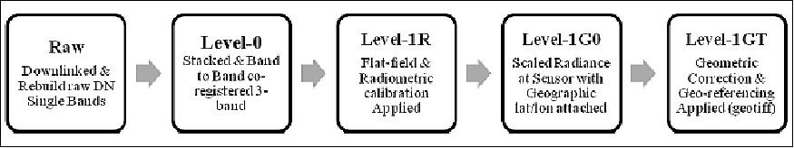
The ISSAC project will deliver three types of Level-1 data products: Level-1R, Level-1G0 and Level 1GT, as is illustrated in Figure 15.
ISERV (ISS-SERVIR Environmental Research and Visualization System)
ISERV is a NASA automated image data acquisition system designed to acquire images of the Earth's surface from the International Space Station (ISS). It deploys in the WORF (Window Observational Research Facility) rack within the Destiny module. It is primarily a means to gain experience and expertise in automated data acquisition from the ISS , although it is expected to provide useful images for use in disaster monitoring and assessment, and environmental decision making. 18) 19)
ISERV functions as a mechanism by which scientists in NASA's SERVIR (Spanish, "to serve") project gain experience and expertise in rapid instrument tasking, automated image data acquisition, and rapid data downlink. While the core purpose of the project is to gain proficiency in these operations in order to inform design criteria and address engineering concerns for a similar but significantly more capable external instrument to be flown aboard ISS at a future date, useful image data is expected to accrue in the process.
Note: the ISERV instrumentation is also referred to as a "Pathfinder instrument" in the literature.
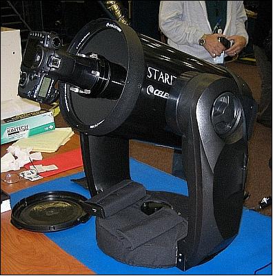
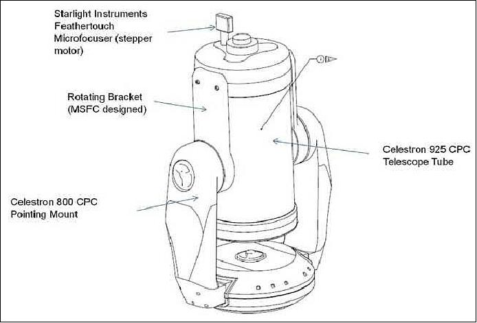
ISERV is a pathfinder imaging system designed and built at NASA/MSFC (Marshall Space Flight Center) in Huntsville, AL. The system, based on a modified commercial telescope and driven by custom software, will use downward viewpoint to obtain near-real-time data about Earth-based environmental disasters, humanitarian crises and environmental threats. ISERV will then transmit that data within hours to scientists back on Earth.
ISERV development was funded as a collaborative effort between NASA's Human Exploration and Operations Directorate and the Science Mission Directorate's Earth Science Division Applied Science Program as part of the NASA/USAID (U.S. Agency for International Development) SERVIR partnership.
ISERV's main component is the optical assembly which consists of a 23.5 cm Schmidt-Cassegrain catadioptric telescope, a focal reducer (field of view enlarger), a digital single lens reflex camera, and a high precision focusing mechanism. A motorized 2-axis pointing mount allows pointing at targets approximately 23º from nadir in both directions along- and across-track. The T61p WORF laptop provides system control, image storage, and data downlink functions. Utilizing a Canon EOS 7D DSLR (Digital Single-Lens Reflex), ISERV images a 13 km x 9 km footprint from a nominal 350 km orbital altitude, capturing up to 390 km2/s of image data in 3-second bursts.
On January 12, 2012, the ISERV instrument was handed to the NASA /JSC (Johnson Space Center) cargo management contractor for final packaging prior to shipment to Japan. 20)
Launch
The ISERV payload was launched to the ISS aboard JAXA's (Japanese Aerospace Exploration Agency) HTV-3 (H-II Transfer Vehicle-3) on July 21, 2012 from TNSC (Tanegashima Space Center) in southern Japan. 21) 22)
After installation, ISERV/Pathfinder will run autonomously using custom ground and on-orbit software developed under contract by TBE (Teledyne Brown Engineering).
Operations Requirements - ISERV
During ISERV's initial operational phase, approximately 60 individual data acquisitions take place, spaced roughly equally over the course of 3 to 6 weeks, that length of time, depending upon variables such as visibility of test targets, local meteorology at test targets, etc. ISERV's secondary operational phase consists of an extended period of operation, acquiring data at regular and irregular intervals as necessary to initialize, develop, and refine operational procedures, and as targets of opportunity (disaster areas, etc.) may become available.
Operational protocols: ISERV acquires image data, stores the data, and downlinks that data according to control scripts uploaded from NASA/MSFC. In response to commands, the telescope system slews (moves) either along- or across-track, or both, as necessary to the ground target within the instrument field of view at a specific time. Per a timing sequence within the control script, ISERV acquires single or multiple digital images that are momentarily stored in the camera's Compact Flash memory, then transferred to the WORF laptop hard disk for storage to be downlinked via TDRSS at the earliest available opportunity. During initial operations, this process is carried out to calibrate instrumentation, and to characterize the as-built performance of the optical system. During secondary operations this process is carried out to initialize, develop, and refine operational procedures necessary for optimization of the acquisition and downlink process with the goal of reducing the amount of time required for each step.
At an operational altitude of ~ 350 km , the ground sample spacing will be approximately 2.8 m. The low altitude of ISS will result in data of a relatively high resolution. It will have an imaging range of latitudes from approximately 53° N to 53° S. The camera will operate in burst mode at ~7 frames/s.
Mission Status - ISERV
• Remotely sensed data acquired by orbital sensor systems has emerged as a vital tool to identify the extent of damage resulting from a natural disaster, as well as providing near-real time mapping support to response efforts on the ground and humanitarian aid efforts. The ISS is a unique terrestrial remote sensing platform for acquiring disaster response imagery. Unlike automated remote-sensing platforms it has a human crew; is equipped with both internal and externally-mounted remote sensing instruments; and has an inclined, low-Earth orbit that provides variable views and lighting (day and night) over 90% of the inhabited surface of the Earth. As such, it provides a useful complement to autonomous sensor systems in higher altitude polar orbits. NASA remote sensing assets on the station began collecting International Charter, Space and Major DisastersDisasters, also known informally as the IDC (International Disaster Charter) response data in May 2012. Since the start of IDC response in 2012, and as of late March 2015, there have been 123 IDC activations; NASA sensor systems have collected data for thirty-four of these events. Of the successful data collections, eight involved two or more ISS sensor systems responding to the same event. 23)
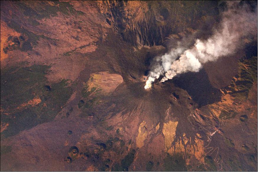
• July 2014: Mount Etna, near the east coast of Sicily, has been in a near-constant state of eruption throughout recorded history. Four major flank eruption events have occurred over the last 15 years, each of which has posed a serious threat to the nearby population. 24)
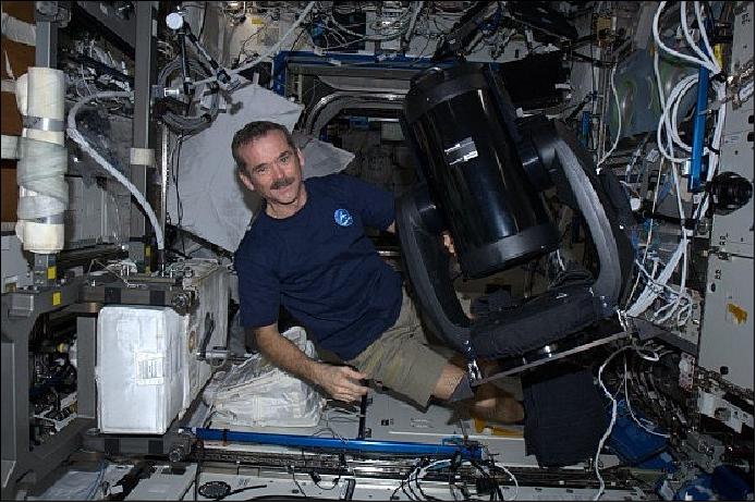
• In mid Febrary 2013, the ISERV instrument transmitted back its first images to scientists on Earth from its location in the WORF (Window Observational Research Facility). This "first light" image, captured on Feb. 16, shows the mouth of the Rio San Pablo in Veraguas, Panama, as it empties into the Gulf of Montijo. 25)
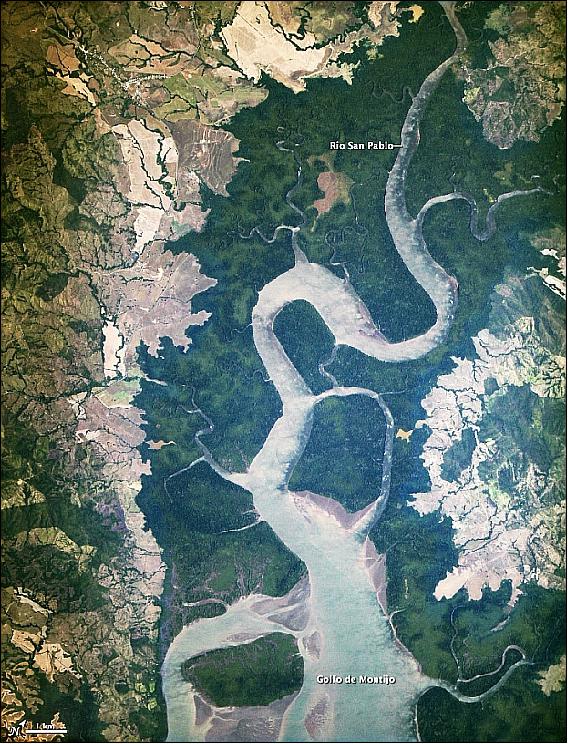
Legend to Figure 19: Where Panama's Rio San Pablo empties into the Golfo de Montijo is an ecological transition zone, changing from agriculture and pastures to mangrove forests, swamps and estuary systems. The area is protected by Panama's National Environmental Authority and listed as a "wetland of international importance" under the Ramsar Convention.
• The ISERV/Pathfinder was installed on-board the ISS in January 2013. The instrument will be controlled from NASA/MSFC in Huntsville, AL, in collaboration with researchers at hubs in Central America, East Africa and the Hindu Kush–Himalaya region. 26)
Background on SERVIR Program
The SERVIR program commenced operations in 2004 at NASA/MSC (Marshall Space Flight Center )in Huntsville, Alabama, USA and officially placed the first SERVIR regional hub at the Water Center for the Humid Tropics of Latin America and the Caribbean (CATHALAC) in Panama in 2005. Two additional regional hubs, located at the RCMRD (Regional Center for Mapping of Resources for Development) in Nairobi, Kenya and ICIMOD (International Center for Integrated Mountain Development) in Kathmandu, Nepal, were established in 2008 and 2010, respectively. 27)
The goal of the SERVIR program is to supplement local facilities, technology, and skills already established in select international areas with expanded satellite imagery and tools to enable more informed decision making locally, regionally, nationally, and internationally. The ultimate goal is to strengthen the capabilities of developing nations to access and utilize Earth observation data so that SERVIR operations can be turned over to host countries. SERVIR also has a broader impact beyond the three regional facilities by increasing the availability of up to date satellite data, including Earth observations and predictive models, for all nations.
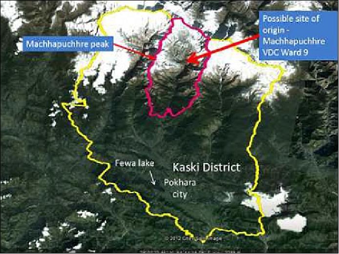
The SERVIR mission is concentrated on the nine GEOSS (Global Earth Observation System of Systems) societal benefit areas: disasters, ecology, weather, climate, oceans, water, agriculture, human health and energy. To date, SERVIR has played an active role in many of these areas. For example, after the 2010 earthquake in Haiti, SERVIR utilized data from the ASTER (Advanced Spaceborne Thermal Emission and Reflection Radiometer (ASTER) instrument on the Terra satellite, and the EO-1 (Earth Observing-1) mission, among others, to compare pre- and post-event imagery was used for damage assessment and resource recovery. In May 2012, SERVIR and SERVIR-Himalaya worked together to determine the cause of deadly flooding in Nepal on May 5, 2012 (Figure 21). They also utilized pre and post-event satellite imagery to aid in rescue efforts and identify damage.
SERVIR-Himalaya is also actively monitoring biodiversity and climate in the Hindu Kush-Himalayan region. Through supporting efforts such as preparation of a resource inventory of the Phojjikha wetland ecosystem in Bhutan, SERVIR-Himalaya works to understand changes in land cover and use and protect biodiversity in important habitats for wildlife such as the black-necked crane. Additionally, SERVIR-Himalaya works to develop tools to support active monitoring of climate factors such as snow melt, and forest fires.
SERVIR-East Africa does a great deal of work with water management. Flooding is a common and destructive issue in east Africa. To help forecast floods, SERVIR uses the CREST (Coupled Routing and Excess Storage) model to provide local government agencies, decision makers, and disaster response organizations with flood predictions. The CREST model was created using actual observations as well as flood inundation maps derived from MODIS (Moderate Resolution Imaging Spectroradiometer) and ASTER data is also cooperating with the KMD (Kenya Meteorological Department) to provide flood incorporate data from NASA's TRMM (Tropical Rainfall Measuring Mission).
The SERVIR team uses a variety of satellites to obtain the data needed to support projects around the globe. Today (2012), the satellites that SERVIR utilizes for data collection are aging and, in some cases, experienced malfunctions that impair the ability to operate properly. Table 1 contains a list of satellites used by SERVIR, the year each satellite was launched, and the expected design life for each satellite at launch.
Mission | Year of launch | Design life (years) | Exceeded design life (?) |
TRMM | 1997 | 3 | Yes |
Landsat-7 | 1999 | 5 | Yes |
Terra | 1999 | 6 | Yes |
ACRIMSat | 1999 | 5 | Yes |
EO-1 | 2000 | 2 | Yes |
Jason-1 | 2001 | 5 | Yes |
GRACE | 2002 | 8 | Yes |
Aqua | 2002 | 6 | Yes |
SORCE | 2003 | 5 | Yes |
Jason-2 | 2008 | 3 | Yes |
QuikSCAT | 1999 | 2 | Yes |
The data in Table 1 illustrates that the satellites used by SERVIR are all beyond their original design lifetimes: in some cases, they have surpassed their estimated functional periods by over ten years. With aging satellites comes uncertainty and risk. Not only have the satellites, commonly used by SERVIR, exceeded their design lifetimes, but some are no longer functioning at full capacity. Landsat-7 has operated under limited functionality due to a sensor malfunction since 2003. Furthermore, Landsat 7 is projected to run out of fuel as early as in 2012. QuikSCAT has also experienced difficulties. In 2009, the primary instrument on QuikSCAT's antenna, Seawinds, experienced a mechanical failure and lost the ability to rotate. This malfunction, though not incapacitating, has resulted in a significantly decreased swath on the instrument and has already negatively impacted the ability of weather forecasters and other scientists to gather data.
Though aging satellites are certainly cause for concern, the more immediate motivation behind the ISERV program is timely access to data. The range of data needed by SERVIR is not entirely available through non-commercial entities. In the event of a major disaster, the UN (United Nations) disaster charter is invoked. This charter gives entities like SERVIR front-of-the-line access to information needed to respond to major disasters.
However, the disaster charter is often not invoked for many of the smaller disasters that SERVIR responds to. In these cases, scientists at SERVIR have to wait in line to purchase commercial data just like any other customer. Competition and demand for satellite data have increased and the supply has not. This is a problem for the SERVIR team because many of the disasters they respond to are emergencies in small areas that are not widespread enough to warrant UN involvement. In these cases, there is a real possibility that scientists at SERVIR will not be able to obtain the data needed to assist those in need in a timely manner. Assisting developing countries to recover from and adapt to natural disasters is a time critical process. Without access to necessary satellite data within the critical windows of time following disasters, the help SERVIR can provide is far below the capabilities of the program and can result in unnecessary loss of life and property.
In response to these factors and to learn how to operate in a new environment such as the ISS, SERVIR has developed ISERV. The ISERV (ISS-SERVIR Environmental Research and Visualization System) program is a low cost alternative to autonomous satellites that will be able to take advantage of the orbit of the ISS. The first ISERV instrument, called Pathfinder, will serve as an engineering prototyping exercise to gain experience that will enable SERVIR to eventually put more capable instruments on the ISS (Ref. 27).
References
2) "ISS Window Observational Research Facility (WORF) - Summary," 2001, URL: http://www.spaceandtech.com/spacedata/platforms/iss-worf_sum.shtml
3) STS-131 Press Kit, NASA, URL: http://www.nasa.gov/pdf/435885main_sts131_press_kit.pdf
4) Mario Runco, Susan Runco, William L. Stefanov, Brion Au, "We Can See Clearly Now: ISS Window Observational Research Facility," NASA. March 4, 2011, URL:
http://earthobservatory.nasa.gov/Features/EarthKAM/?src=features-recent
5) Fact Sheet, NASA, Sept. 17, 2010, URL: http://www.nasa.gov/mission_pages/station/science/experiments/WORF.html#description
6) "Window Observational Research Facility (WORF)," MSFC, URL: http://ntrs.nasa.gov/archive/nasa/casi.ntrs.nasa.gov/20070031903_2007030977.pdf
7) Douglas R. Olsen, Ho Jin Kim, John D. Odegard, "International Space Station Agricultural Camera (ISSAC)," North Dakota GIS Users Conference 2011, Grand Forks, ND, USA, October 11-13, 2011, URL: http://www.nd.gov/gis/news/2011pres/olsen-kim-keynote2.pdf
8) https://web.archive.org/web/20120609033951/http://www.umac.org/sensors/issac/overview.html
9) Douglas R. Olsen, Ho Jin Kim, Jaganathan Ranganathan, Soizik Laguette, "Development of a low-cost student-built multi-spectral sensor for the International Space Station," SPIE Optics + Photonics 2011, San Diego, CA, USA, August 12-16, 2011 [web source no longer available]
10) "Agricultural Camera (AgCam),"May 25, 2010, URL: http://www.nasa.gov/mission_pages/station/science/experiments/AgCam.html#publications
11) "International Space Station Agricultural Camera (ISSAC)," NASA Fact Sheet, March 22, 2012, URL: http://www.nasa.gov/mission_pages/station/research/experiments/ISSAC.html
12) Douglas R. Olsen, Ho Jin Kim, "International Space Station Agricultural Camera (ISSAC)," North Dakota GIS Users Conference 2011, Grand Forks, ND, October 11-13, 2011, URL:
http://www.nd.gov/gis/news/2011pres/olsen-kim-keynote2.pdf
13) https://web.archive.org/web/20080516214347/http://www.umac.org/sensors/agcam/eng.html
14) https://web.archive.org/web/20120609033930/http://www.umac.org/sensors/issac/launch.html
15) Ken Kremer, "Japans White Stork Kounotori Grappled and Nested at Space Station: Video,Photo Album," Universe Today, Jan. 27, 2010, URL:
http://www.universetoday.com/82884
japans-white-stork-kounotori-grappled-and-nested-at-space-station-videophoto-album/
16) "NASA ISS On-Orbit Status 1 April 2012," SpaceRef, April 1, 2012, URL: http://www.spaceref.com/news/viewsr.html?pid=40432
17) "ISSAC™ / Summer-Fall 2011," URL: http://www.umac.org/sensors/issac/index.html
18) "ISS SERVIR Environmental Research and Visualization System (ISERV)," NASA Fact Sheet, March 22, 2012, URL: http://www.nasa.gov/mission_pages/station/research/experiments/ISERV.html
19) Janet Anderson, "SERVIR: Expanding Sensor Networks from the Ground to the International Space Station," NASA/MSFC, April 16, 2012, URL: http://www.nasa.gov/mission_pages/servir/servir_iss_120415.html
20) "SERVIR Delivers ISERV Instrument for Launch to ISS," URL: http://servirglobal.net/Global/Articles/tabid/86/Article/1087
/servir-delivers-iserv-instrument-for-launch-to-iss.aspx
21) Steve Cole, Janet Anderson, "Earth-observing Camera Launches to International Space Station," NASA, July 19, 2012, URL: http://www.nasa.gov/mission_pages/station/research/news/iserv.html
22) "Earth-observing Camera Launches to International Space Station," Space Daily, July 23, 2012, URL:
http://www.spacedaily.com/reports
/Earth_observing_Camera_Launches_to_International_Space_Station_999.html
23) W. L. Stefanov, C. A. Evans, "Data Collection for Disaster Response from the International Space Station," 36th International Symposium on Remote Sensing of Environment, 11–15 May 2015, Berlin, Germany, URL:
http://www.int-arch-photogramm-remote-sens-spatial-inf-sci.net
/XL-7-W3/851/2015/isprsarchives-XL-7-W3-851-2015.pdf
24) "ISS SERVIR Environmental Research and Visualization System (ISERV)," NASA, International Space Station, Nov. 22, 2016, URL:
https://www.nasa.gov/mission_pages/station/research/experiments/867.html#publications
25) Janet Anderson, "First Light for ISERV Pathfinder, Space Station's Newest 'Eye' on Earth," Space Daily, April 6, 2013, URL: http://www.spacedaily.com/reports
/First_Light_for_ISERV_Pathfinder_Space_Stations_Newest_Eye_on_Earth_999.html
26) "Space Station's New EO Sensor Springs into Action," Earth Imaging Journal, March 3, 2013, URL: http://earthobservatory.nasa.gov/IOTD/view.php?id=80561
27) Samantha Shine, Tom Sever, Paul Componation, Lindsay Shine, "Utilizing the International Space Station as an Alternative to Support the Regional Visualization and Monitoring System," Proceedings of the 63rd IAC (International Astronautical Congress), Naples, Italy, Oct. 1-5, 2012, paper: IAC-12-B1.3.6
The information compiled and edited in this article was provided by Herbert J. Kramer from his documentation of: "Observation of the Earth and Its Environment: Survey of Missions and Sensors" (Springer Verlag) as well as many other sources after the publication of the 4th edition in 2002. - Comments and corrections to this article are always welcome for further updates (eoportal@symbios.space).
WORF Layout ISSAC ISSAC Launch ISERV ISERV Launch References Back to top