ISS: SPHERES
Technology Development
ISS Utilization: SPHERES (Synchronized Position Hold Engage Re-orient Experiment Satellites)
SPHERES is an experimental testbed to demonstrate the dynamics of formation flight (FF) in satellite systems. The program was developed and installed at the SSL (Space Systems Laboratory) of MIT (Massachusetts Institute of Technology) to provide the USAF (United States Air Force) and NASA with long-term, replenishable, and upgradable test capabilities for the validation of high risk metrology, control, and autonomy technologies. DARPA (Defense Advanced Research Projects Agency) is a major sponsor of the SPHERES program which started in the late 1990s. 1) 2) 3) 4) 5) 6)
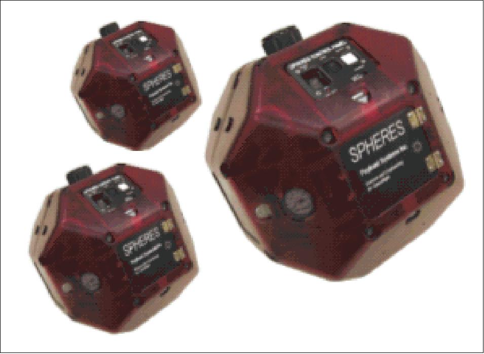
The nanosatellites were originally designed by MIT students (under a program funded by MIT, DARPA and NASA), and built by Payload Systems Inc. of Cambridge, MA. The first operational prototype was completed in the winter 2000 and tested in the laboratory. Two additional units were fabricated in the spring of 2000. Initial flight test experiments, evaluating both testbed and control algorithm performance, were conducted (in 2000, 2001 and 2003) onboard NASA's KC-135 aircraft (three flight campaigns). The idea of SPHERES system testing and research on ISS (with its sustained zero-g environment) for a broader spectrum of applications was a natural consequence after the successful flight campaign demonstrations. 7) 8) 9) 10) 11) 12)
The overall objectives include the demonstration of the following functions: Autonomous rendezvous, docking, and reconfiguration” algorithms, testing of relative attitude control and station-keeping between satellites, re-targeting and image plane filling maneuvers, collision avoidance and fuel balancing algorithms, and an array of geometry estimators used in various missions. A main goal of SPHERES is to support research in distributed aperture control for such applications as telescope arrays - by substituting several smaller, separated mirrors for one large mirror. The SPHERES program technologies are critical to the operation of distributed satellite and docking missions such as TPF (Terrestrial Planet Finder) of NASA and OE (Orbital Express) of DoD.
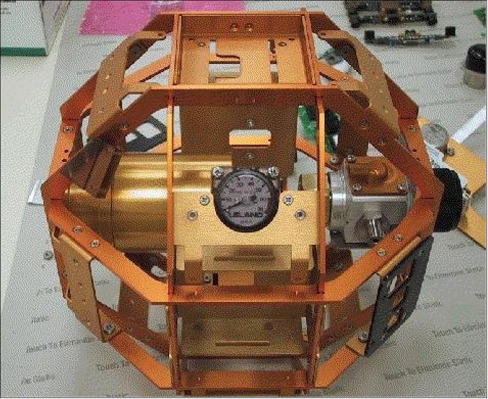
SPHERES Nanosatellites
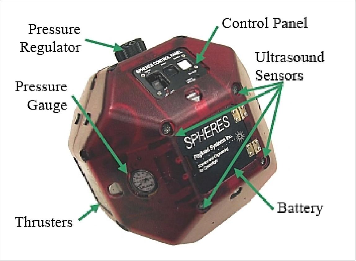
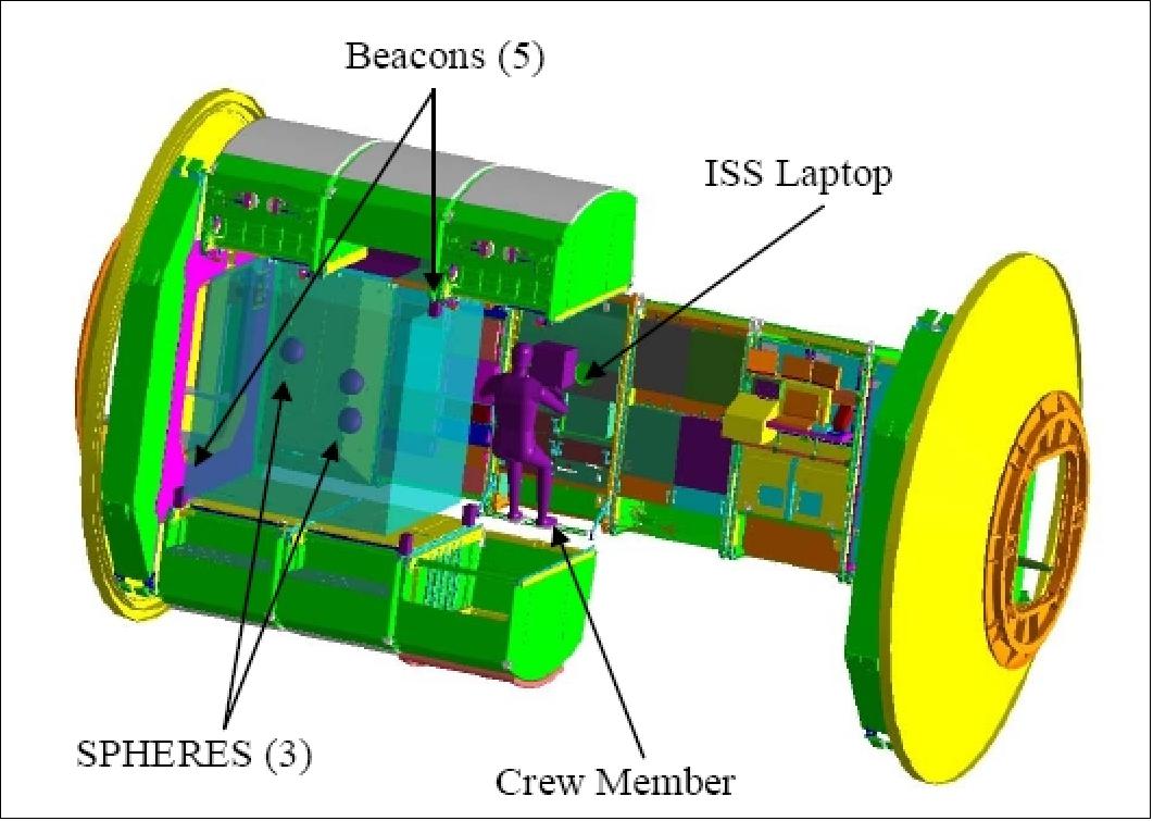
The SPHERES satellites are self-contained with on-board propulsion, processing, RF communication, and metrology. In addition, the testbed has four metrology transmitters that provide global metrology reference and a laptop computer that acts as a “ground station” and provides experiment control.
All SPHERES satellites are identical in structure and internal composition. The SPHERES satellite design is modular. The design of the individual subsystems can be easily integrated into another project which use different configurations due to their simple interfaces and operational independence. The modularity enables a wide spectrum of flexibility in the use of the facility. The SPHERES system consists of the following basic elements: 13) 14)
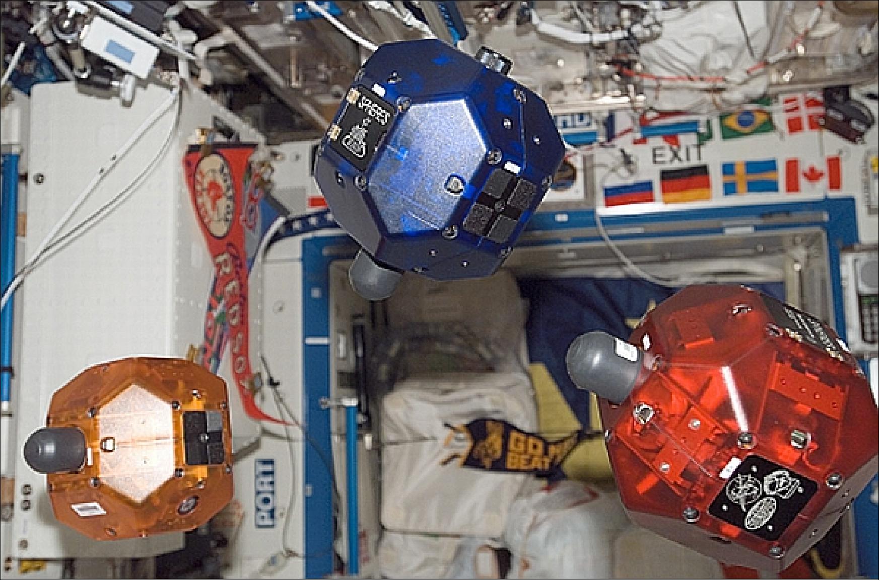
• Three experimental self-contained 20 cm diameter free-floating nanosatellites (each with a dry mass of 3.55 kg, wet mass of 4.16 kg) which perform the various algorithms. The self-contained nanosatellites that are 18-sided polyhedrons.
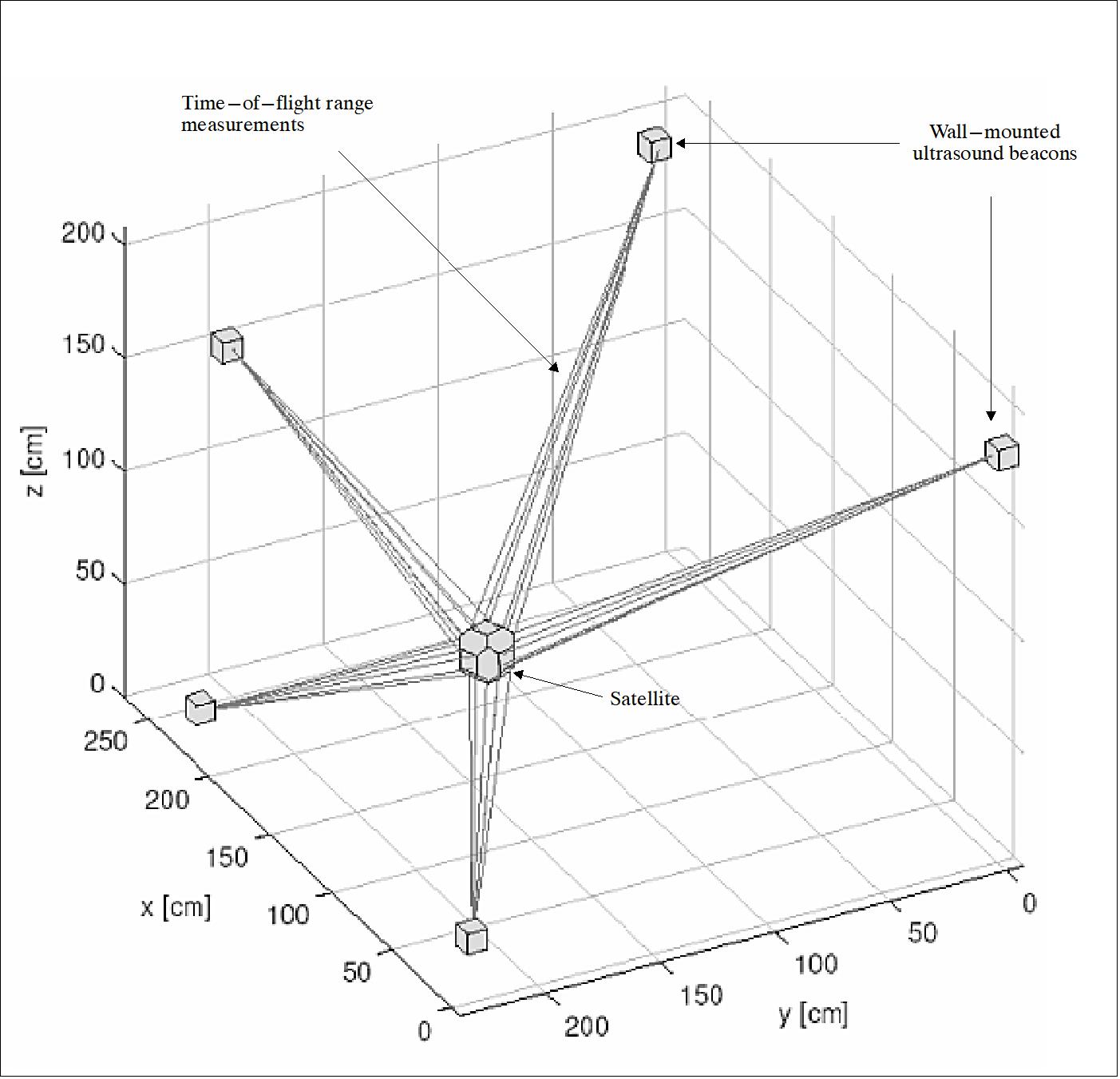
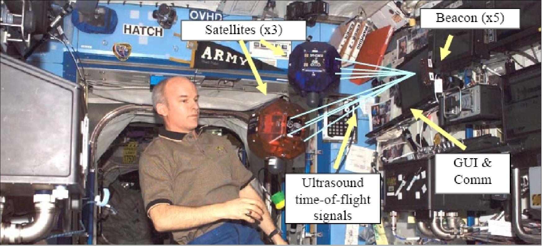
• Five small ultrasound beacon devices are located in the SPHERES work envelope, they are acting as the navigation system (metrology beacon system). The ultrasound transmitter beacons measure their respective positions and attitudes in relation to one other and to the defined volume. Each beacon is self-contained and uses two standard Duracell Ultra AA batteries.
• The nanosatellites communicate with each other and an ISS laptop through a low-power wireless (RF) link.
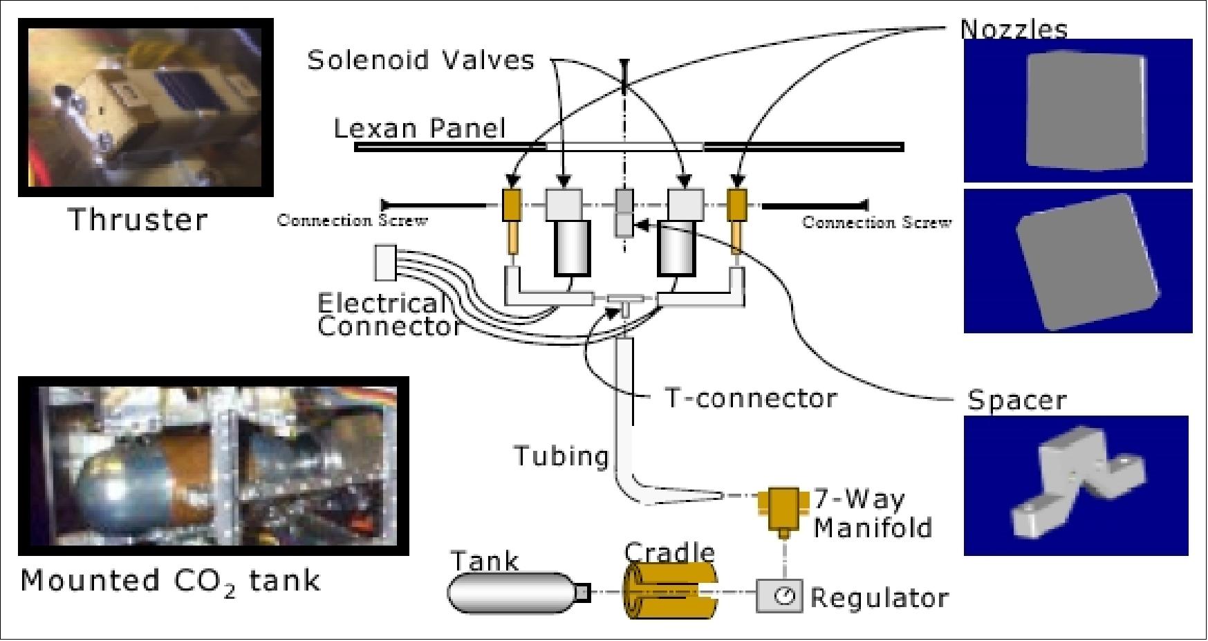
Each of the nanosatellites contains an internal cold gas propulsion system, power, avionics, software, communications and metrology subsystems. The propulsion system uses carbon dioxide (CO2) which is expelled through thrusters. The SPHERES nanosatellites are powered by AA batteries. The metrology subsystem provides real-time position and attitude information. To simulate ground station keeping, a laptop is being used to transmit navigational data, and formation flight algorithms.
Diameter | 22 cm |
Dry mass, wet mass | 3.55 kg, 4.3 kg (with tank and batteries) |
Thrust | 0.2 N |
Power, battery lifetime | 13 W, 2 hours (replaceable) |
Linear acceleration, angular acceleration | 0.17 m/s2 (max), 3.5 rad/s2 (max) |
CO2, internal pressure level | 170 gram, 59 - 3.45 bar (high & low pressure of storage tank) |
RF communications (UHF band) | 916.5 MHz (± 1MHz), 868.35 MHz (± 1MHz) |
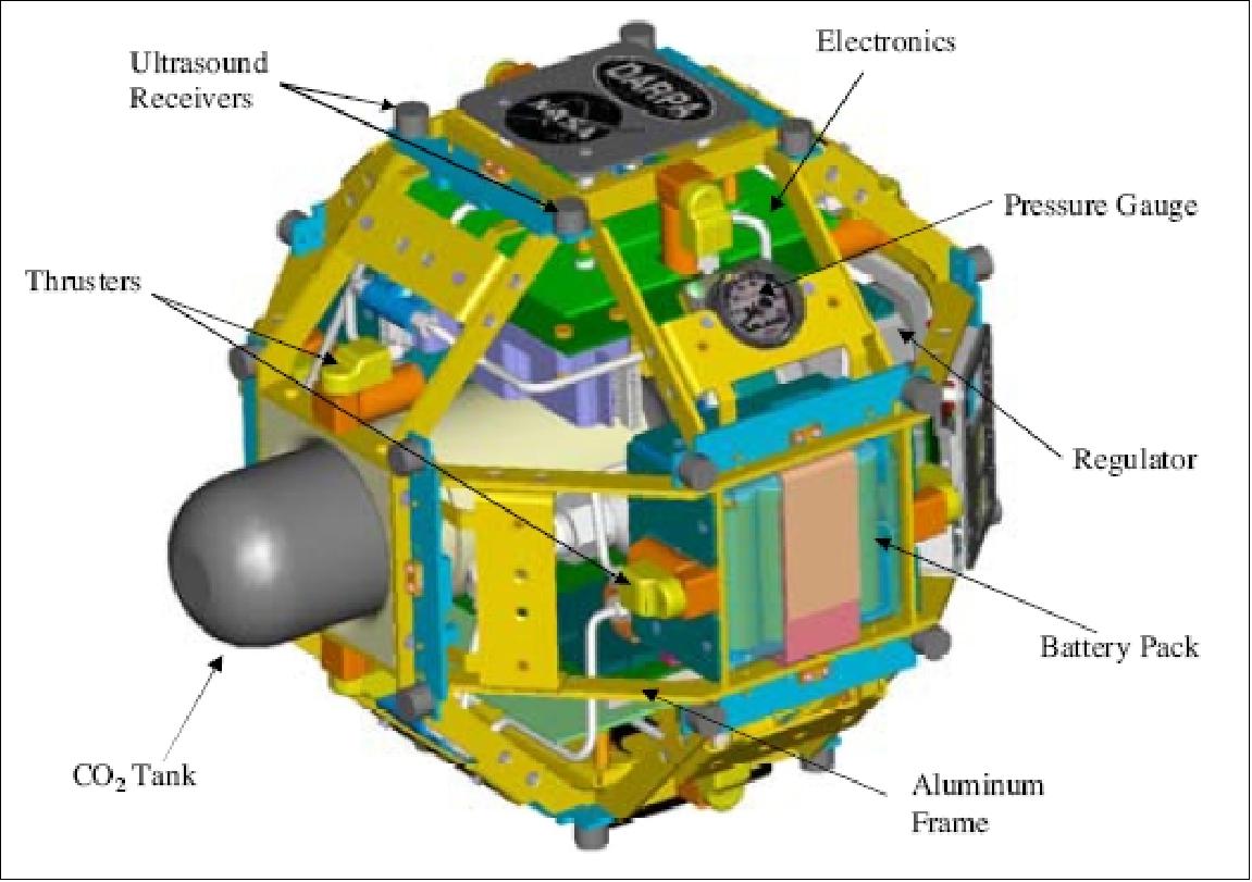
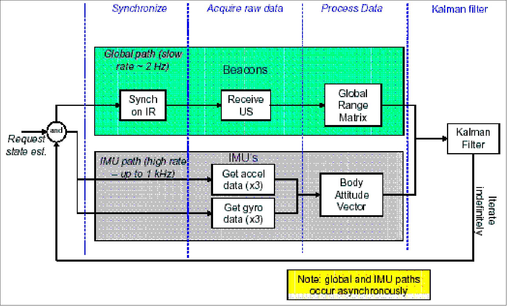
PADS (Position and Attitude Determination System). The objective of PADS is to provide real-time position and attitude information to each nanosatellite. PADS consists of: 15) 16)
• Ultrasonic beacons attached to the work envelope “walls” and ultrasonic receivers located onboard each nanosatellite (the beacon locations define the operational volume or the outer perimeter of the work envelope). The ultrasonic beacons provide low-rate (1-2 Hz) satellite position and attitude information relative to the work envelope.
• IMUs (Inertial Measurement Units) consisting of accelerometers and rate gyroscopes located on board each nanosatellite.
Parameter | Accelerometers (Q-Flex 750) | Gyroscopes (BEI Gyrochip II) |
Measurement range | ±25.6 mg | ±80º/s |
Resolution | 12.5 µg/count | 0.0407º s-1 count-1 |
Bandwidth | 300 Hz | 300 Hz |
Noise | < 7 µg rms (for 0 to 10 Hz) | 0.05º/s (Hz)1/2 (for 0 to 100 Hz) |
Time-of-flight ranging (operational scenario):
- “Master” satellite requests a global reading by emitting an IR flash
- Satellites turn off thrusters to listen for the ultrasonic pulses
- Beacons respond to IR flash with ultrasonic pulses
- Receivers on the satellite record the times when the ultrasonic pulses are received
- Satellites compute ranges based on the time of flight of the pulse
- Satellites calculate position and attitude from ranges.
SPHERES on ISS (International Space Station)
The SPHERES payload was scheduled to fly on Shuttle flight (STS-114) in July 2003 to be installed on ISS (International Space Station). However, SPHERES experienced several times long delays due to the loss of Shuttle Columbia (STS-107) and its crew of 7 astronauts on Feb. 1, 2003. The accident resulted into the largest investigation ever by NASA. As a consequence of the investigation, the ISS build-up phase came to a complete halt. The very next Shuttle flight (STS-114) took place on July 26, 2005, ending 2 1/2 years of Shuttle grounding.
The first sphere of three of the SPHERES payload was taken to the US Laboratory (Unity) of the ISS on April 24, 2006. The ISS service flight was provided by a Soyuz-U launch vehicle with the Progress M-56 payload from Baikonur, Kazakhstan. Two additional spheres of SPHERES are scheduled to reach the space station, as payloads of a Shuttle mission, by the end of 2006. The micro-gravity environment of the ISS allows for maneuvers in 6 DoF (Degree of Freedom). The allocated test space (work envelope) in the US Lab has dimensions of about 1.5 m x 1.5 m x 2.m. 19) 20)
The ISS testbed provides a risk-tolerant environment capable of testing unknown algorithms and recovering from failures at low costs compared to that of a full mission. The program provides near-real-time human control and observability for guest scientists in a ground station, and in addition a manipulation capability by operators in the ISS.
The SPHERES testbed consists of two parts; a ground testbed located at MIT/SSL, and a flight testbed in the ISS that is being operated by astronauts as an interactive laboratory. The ISS provides unique opportunities for:
- Supervised and interactive experimentation
- Immediate assessment of test results
- Space research in a risk-tolerant environment
- Experimentation in three dimensional microgravity dynamics.
The SPHERES elements on ISS can maneuver in six degrees of freedom, communicate with each other and with the laptop control station, and determine their positions, velocities, attitudes, and angular rates with respect to an ISS-fixed or labfixed reference frame. 21)
Maneuvers are performed using a cold-gas propulsion system. Each thruster assembly consists of a solenoid-actuated valve with a micro-machined nozzle. Twelve thruster assemblies are positioned in pairs to provide complete attitude and position control. The propellant is stored in removable tanks. Each tank is expected to provide approximately 30 minutes of active operation in microgravity under normal operation on the ISS.
The SPHERES program on the ISS is led by MIT/SSL and Aurora Flight Sciences, and supported by the DoD/DARPA (Defense Advanced Research Projects Agency) and STP (Space Test Program) as well as by NASA.
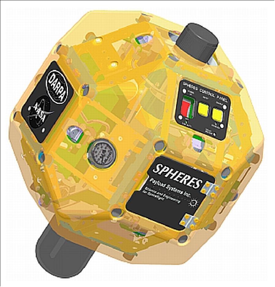
Each sphere features an onboard DSP (Digital Signal Processor) of Texas Instruments (model C6701) providing ample computational power and flexibility (up to 167 MFLOPS with un-optimized code, and up to 1.0 GFLOPS with fully-optimized code). The flight software is stored in FLASH memory, and may be up to 224 kB in size.
Two packs of AA batteries provide power for each sphere. A set of batteries provides power for two hours of typical operation.
RF communications: Each satellite is equipped with two low-power transceivers for inter-satellite communication and satellite-to-laptop communication. The spheres communicate on two separate radio channels. Each channel has an effective capacity of about 22 kByte/s. One channel is dedicated to sphere-to-sphere (STS) communications, the other channel is used for sphere-to-laptop (STL) communications. The STS channel is typically being used for user-defined algorithm coordination, while the STL channel handles telemetry downlink and command uplink. Both channels are bi-directional; however, the communication hardware is half-duplex, meaning that only one station on each channel can transmit at a time.
Launch of next SPHERES payloads
• The second satellite arrived on STS-121 flight of Discovery, July 4-17, 2006 (13 day mission). The arrival allowed testing of a “two satellite configuration” which started in August 2006.
• The third one arrived on flight STS-116, Discovery, Dec. 10-22, 2006 (13 day mission).
Hence, experimentation with the complete SPHERES system configuration commenced inside the ISS in 2007.
Test Sessions Aboard the ISS
Five test sessions were conducted aboard the ISS during 2006: May 18, May 20, August 12, August 19, and November 11. A test session with the first single sphere took place on May 18, 2006 - floating inside the ISS and being watched by the astronauts. The first test flight consisted of a series of 10 to 15 pre-planned maneuvers, each lasting up to 10 minutes. 22)
The first four sessions helped the SPHERES team achieve steady-state operations, having fully understood the microgravity capabilities and behavior of the facilities and the ISS. Using the data collected from each test session, the SPHERES team incrementally matured formation flight and docking algorithms resulting in multiple “space firsts.” On the second test session it was the first space program to intentionally simulate failures of thrusters in space in order to test fault detection algorithms. During the fifth session SPHERES was the first to demonstrate docking to a tumbling target in a microgravity environment. The circular formation flight was another first (demonstrate covering an optical field in a microgravity environment with separated spacecraft), although there were synchronization problems that prevented the test from being fully successful, so it requires further research. - SPHERES is expected to operate aboard the station for multiple years to complete these tasks and more.
Session | Objectives |
1 | - Hardware checkout |
2 | - Firmware fix (from session 1) |
3 | - Autonomous docking to a fixed beacon |
4 | - Global metrology system checkout |
5 | - Continue tests for mass-ID |
GSP (Guest Scientist Program)
The SPHERES GSP provides a common framework for collaboration, and facilitates access to the SPHERES laboratory (distributed architecture). It is designed to support parallel use of the testbed by researchers with diverse research interests and goals. Specifically, the GSP enables geographically distributed researchers to implement and test algorithms, obtain experiment data, iterate on algorithm design, and otherwise participate fully in the ground and flight laboratories on time scales of days and weeks rather than years. 23)
In 2006, the GSP started already; the first test sessions had participants from a different group within MIT and with NASA Ames.
Prior to sending SPHERES algorithms to the ISS, the scientists conduct tests on the SPHERES flat table testbed in the MIT SSL laboratory. The flat table testbed uses the same flight hardware that is onboard the ISS, but the SPHERES are mounted on air carriages to float on it.
The Reconfiguration Maneuver Problem for Multiple Spacecraft in Deep Space Environment
There are two key types of trajectory design problems for formation flying spacecraft: 24)
1) Reconfiguration, which consists of maneuvering a fleet of spacecraft from one formation to another
2) Station-keeping, which consists of keeping a cluster of fleet of spacecraft in a specific formation for a determined part of the trajectory.
Both types of formation flying maneuvers must be addressed for deep-space missions where the relative spacecraft dynamics usually reduces to double integrators, or planetary orbital environment flying missions where spacecraft are subjected to significant orbital dynamics and environmental disturbances.
The SPHERES experiments were designed using two different two-stage path planning algorithms previously developed to solve the general multispacecraft translation and rotation reconfiguration maneuver problem with coupled constraints. This problem is particularly difficult because of the nonlinearity of the attitude dynamics, the non-convexity of some of the constraints, and the coupling between the positions and attitudes of all spacecraft. 25)
In March and April 2007, some reconfiguration experiments were performed with SPHERES on ISS which allowed to test the reconfiguration maneuver algorithms in real microgravity environment. - The ISS experiments achieved their main goal: the application of the two-stage reconfiguration maneuvers design to real satellites in a microgravity environment, thus validating the algorithms used to design them.
ZERO-Robotics Program
In 2009, MIT started the ZERO-Robotics program which provides high school students the opportunity to develop algorithms for SPHERES on board the ISS. Students work on the design of software to accomplish complex tasks in space; such as docking, assembly, and formation flight. As for the competition, each team must complete a set of pre-determined tasks, whereby they are measured for performance. During all phases, the students will be challenged not only with programming, but also with the development of documentation and presentations to add to their engineering and communication skills. In all cases, the students will have to learn and practice successful teamwork skills as there will be minimum team size requirements. 26)
There are four steps in the competition:
1) Proposal submission: Students propose a solution to the challenge of the competition. Students should clearly outline the motivation, the science behind their algorithm, how they will implement it, and data they expect to collect to show it worked properly. This phase is intended to teach students the basics of writing a proposal. This step also serves as a registration step. Teams are not eliminated at this step.
2) Simulation: Students implement their algorithm in simulation. This step verifies successful algorithm implementation, prior to hardware testing, and allows for a baseline performance expectation. If the number of teams participating is greater than can be accommodated in flight, this step can be used as an elimination round.
3) Ground Testing: Teams translate their algorithms from simulation to hardware, accounting for computation and communication limitations. Teams that demonstrate correctly operating simulations are invited to MIT's flat floor facility in Cambridge, MA to test them. Teams are selected based on the performance of hardware tests.
4) Flight Testing: The selected teams will modify their algorithms for implementation in space. Tests are integrated and packaged to be run on ISS. This step includes at least one ISS test session, with live feed of the crew executing the tests. Students will have the opportunity to view their test run in real-time. Data and telemetry will be downlinked to the students a few days after the event so that they can perform data analysis and submit a final report.
ZERO-Robotics is envisioned as a robotics competition that opens the world-class research facilities on the ISS to hundreds (potentially thousands) of students at multiple educational levels. A key objective is to inspire future scientists and engineers by making the benefits and resources of the space program tangible to the students. In this way, students will view working in space as reachable objective that is not just reserved for astronauts, and will grow up pushing the limits of space exploration, engineering, and development. Further, ZERO-Robotics helps build critical engineering skills for students, such as problem solving, design thought process, operations training, team work, and presentation skills.
The goal of the ISS as a National Laboratory is to educate them at a deeper level that keeps students interested in science, technology, engineering, and mathematics (STEM).
• Pilot program: A pilot Zero-Robotics program was started in the fall of 2009 with students from two High Schools in Idaho. The pilot program did not require the teams to create proposals, and there was no “elimination” rounds. However, they did compete against each other in simulation, on the flat floor, and aboard the ISS. In mid-December 2009, the teams of the 2 schools successfully executed their SPHERES control software on the station (assistance from MIT).
• National program: The conclusion of the pilot program marks the start of the preparations for the first year (2010) of a national program. Several organizations form part of the ZERO-Robotics efforts: MIT SSL, Aurora Flight Sciences, the Space Grant Program, DARPA, and NASA (Ref. 26).
- The MIT SPHERES team leads the academic and software development efforts (tutorials, simulations, competition scenarios, etc).
- Aurora Flight Sciences ensures the continued operation of SPHERES aboard the ISS by manufacturing and providing SPHERES supplies.
- The Space Grant program has been approached to become the general administration and to provide public relations and human resources.
- The NASA Education Office is expected to have at least one person be a full time liaison to the program, working with crews and public relations teams.
- DARPA, the original sponsor of SPHERES, will participate by providing further public relations and being a source of ideas for the competitions; there is the potential of DoD sponsored scholarships for participants/winners.
VERTIGO (Visual Estimation for Relative Tracking and Inspection of Generic Objects)
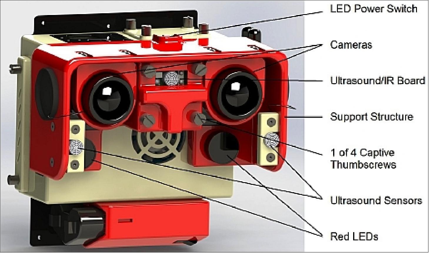
In 2008, the MIT/SSL ( Space Systems Laboratory) began a program to develop an upgrade to the SPHERES satellites that would allow it to perform vision based navigation experiments onboard the ISS. This was the LIIVe (Low Impact Inspection Vehicle) program that was sponsored by the Office of Naval Research and NRL (Naval Research Laboratory). This program’s intent was to develop a high-fidelity prototype of the hardware that could be launched to the ISS under a future program. This program resulted in the design and fabrication of the LIIVe Goggles, shown in Figure 14. 27) 28) 29) 30)
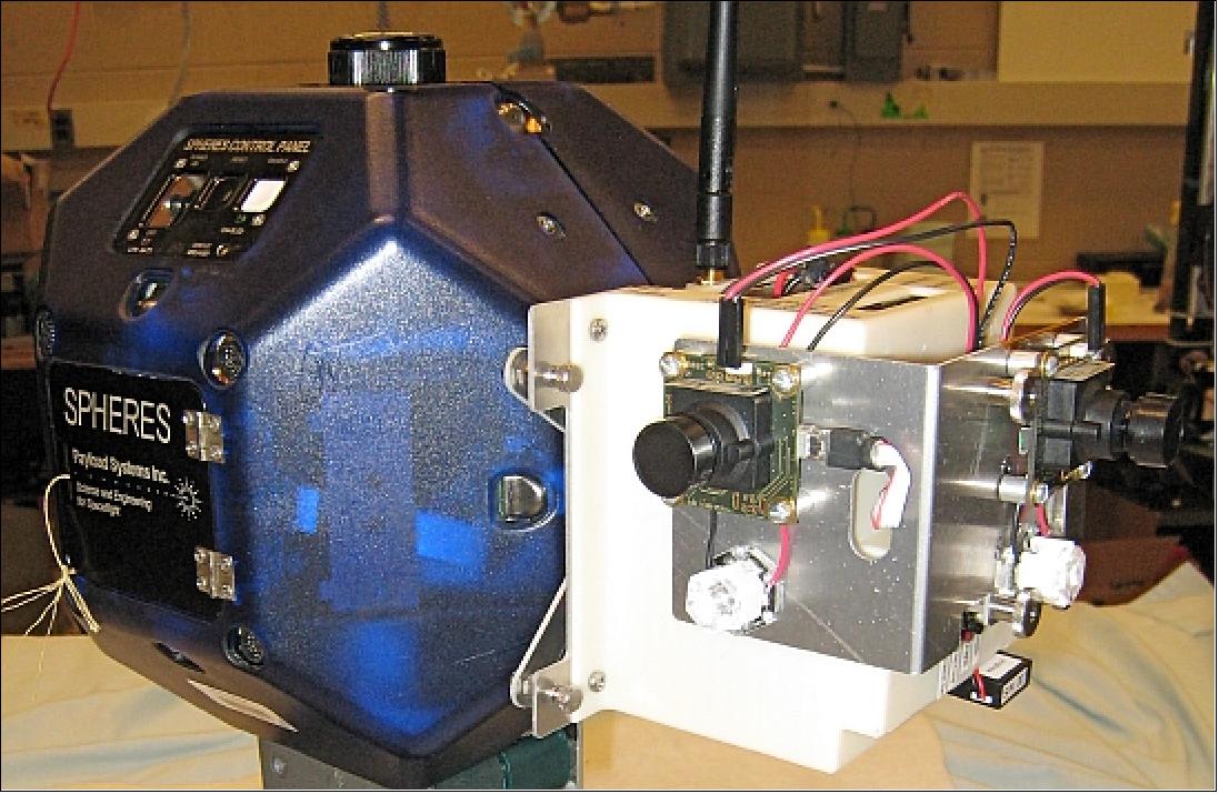
The LIIVe Goggles add two grayscale cameras (in either stereo or right angle configurations), a 1.0 GHz Via C7 x 86 microprocessor, a 16 GB flash drive, illuminating LED lights, an 802.11g network card and lithium polymer batteries to power the Goggles. Under the LIIVe program a number of vision based navigation experiments were performed for both cooperative and non-cooperative target inspection.
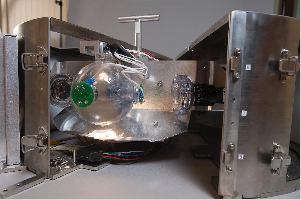
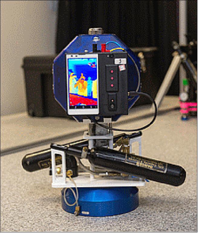
VERTIGO Goggles: In 2010, the MIT/SSL and Aurora Flight Sciences began the DARPA sponsored VERTIGO (Visual Estimation and Relative Tracking for Inspection of Generic Objects) program. This program was to refine and launch the Goggles developed under the LIIVe program as well as perform additional research on inspection of unknown, non-cooperative targets that are possibly moving and tumbling. The Goggles received a number of minor tweaks and upgrades. The final ISS-flight version of the Goggles are shown attached to a SPHERES satellite at the MIT/SSL (Figure 15).
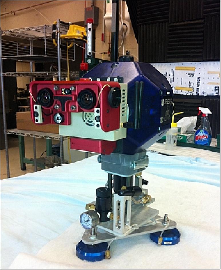
The processor was upgraded to a Via 1.2 GHz Via Nano, the network card was upgraded to 802.11n, the battery was changed to a unit that was already onboard the ISS, and the optics were upgraded to a larger aperture lens that was in a synchronized stereo configuration. An additional flash drive was added to create a total of 128 GB of storage space. The mechanical design was refined to meet the requirements of operations inside the ISS.
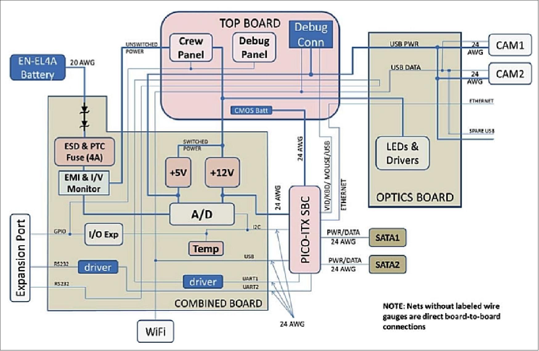
The schematics for the Goggles electronics system and the overall integrated layout is shown in Figures 16 to 18. The average power consumption of the Goggles is approximately 24 W, but can vary between 14 and 30 W depending on the system load.
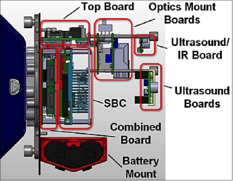
One of the main design features of the Goggles is future upgradeability. The design incorporates two methods for upgrading future systems. The first is a detachable optics mount . The optics mount contains the CMOS camera sensors, lenses, illuminating LEDs and additional circuitry. The interface between the Goggles avionics stack and the optics mount is an electro-mechanical connection. The mechanical connection consists of four captive thumbscrews which can be removed to detach the optics mount. The electrical connection provides 12 V power, USB, ethernet and RS232 data to interface with the SPHERES and Goggles. The optics mount could be replaced by another piece of hardware that has different sensors or other capabilities. Example upgrades could include cameras in a different configuration or different model, or could even contain a different sensor system entirely (i.e. a LIDAR system). The second method for upgrading the Goggles is via the 802.11n connection. Off-board processing systems could be added that process the images that are captured by the Goggles and streamed over the wireless network.
VERTIGO program status: SPHERES-VERTIGO was launched to the ISS on a Soyuz spacecraft from the Baikonur Cosmodrome, Kazakhstan on October 23, 2012.
SSE (SPHERES Slosh Experiment)
Sloshing problems are of increasing concern in a rocket upper-stage and spacecraft applications. In microgravity, the influence of sloshing liquid propellants may influence critical maneuvers such as docking of cargo vehicles or pointing of satellites. The confidence in CFD (Computational Fluid Dynamics) predictions are low because of the lack of benchmark against experimental data. The goal of the SSE (SPHERES Slosh Experiment) is to acquire long-duration, low-gravity liquid slosh data aboard the International Space Station. 31) 32)
• ISS offers opportunity to acquire low-gravity slosh data
• Leverage proven SPHERES hardware on ISS
• World’s first long duration liquid slosh database.
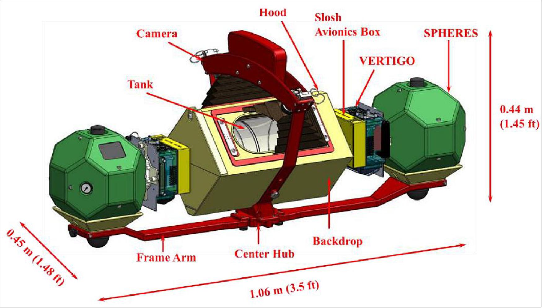
The SSE was built by FIT (Florida Institute of Technology) of Melbourne, FL, to investigate in the matter. It makes use of two SPHERES units, connected by a frame. Multiple plastic pill shaped tanks partially filled with water are used, with fill fractions of 20%, 40% and a solid mass replicator, representing the 40% fill fraction tank evenly distributed. High resolution cameras record the movement of the liquid inside the tank as the experiment maneuvers within the ISS test volume, either driven by SPHERES or manually by the crew member. Inertial measurement units record the accelerations of the tank, making the combination of stereo imaging and inertial data the inputs for CFD (Computational Fluid Dynamics) model validation. 33) 34)
Launch
The SSE equipment was launched on January 9, 2014 on the Cygnus CRS Orb-1 (Cargo Resupply Mission-1) of Orbital Sciences, contracted by NASA, to the ISS. The Cygnus CRS Orb-1 is the second flight of the Orbital Sciences Cygnus unmanned resupply spacecraft to the ISS.
The core of the SSE consists of a partially filled (with water) transparent tank fitted to a structural frame and two cameras (in orthogonal configuration) recording the liquid distribution (Figure 19). Two sets of IMUs (Inertial Measurement Units) are used to record the inertial measurements. The SSE utilizes the manifested SPHERES laboratory and will use the VERTIGO platform (already on-board the ISS). The SPHERES units propel the SSE and the VERTIGO units are used to record the captured IMU/camera data on its local hard drives. Adequate lighting for image capture is provided via LED panels, installed within the Backdrop and Hood. The Slosh Avionics Box contains the IMUs and also provides power to the Camera and the LED panels through the VERTIGO unit. Each of the Slosh Avionics Boxes connects to a VERTIGO unit. The VERTIGO-Slosh Avionics Box packages then connect to the SPHERES units via the SPHERES expansion port. Each SPHERES unit resides within the Frame Arm saddles and is clamped down during the SSE operation. During test sessions, different maneuvers are performed, based on the specific science needs set for the session. These maneuvers include investigation of a wide variety of microgravity slosh phenomena, from CFD correlations to advanced space vehicle maneuvers, planned along with both government agencies and commercial partners.
A total of nine science sessions are being executed onboard the ISS. By August 2015, 5 science sessions have been completed, with three more planned.
Session | Tank Volume | Date |
Checkout | 40% | January 22, 2014 |
Session 1 | 40% | February 28, 2014 |
Session 2 | 20% | June 18, 2014 |
Session 3 | 20% | September 09, 2014 |
Session 4 | 40% | July 17, 2015 |
Session 5 | 40% | August 07, 2015 |
Session 6 | 40% | September 2015 |
Session 7 | TBD | TBD |
Session 8 | TBD | TBD |
The first session consisted in a full checkout of the experiment, inspecting for potential damage to the payload during transportation to the ISS, as well as a first back of data runs. Science sessions 1, 2 and 3 targeted optimization of the data, with an emphasis on creating proper initial conditions for the fluid.
In order for the data to be useful for validating and anchoring CFD models, the maneuvers must begin with the fluid in a configuration that is uncomplicated and easily reproduced. Overly complex initial conditions cannot be accurately reproduced in CFD, causing the simulation to be inaccurate.
After realizing that the initial condition in the tank is not conducive to CFD validation, it was decided that any future sessions would attempt to remove the bubbles and create a less complicated initial condition. After the checkout session was completed, the team set out to resolve the initial conditions problem by developing maneuvers that should cause the air to separate from the liquid and develop a good initial condition.
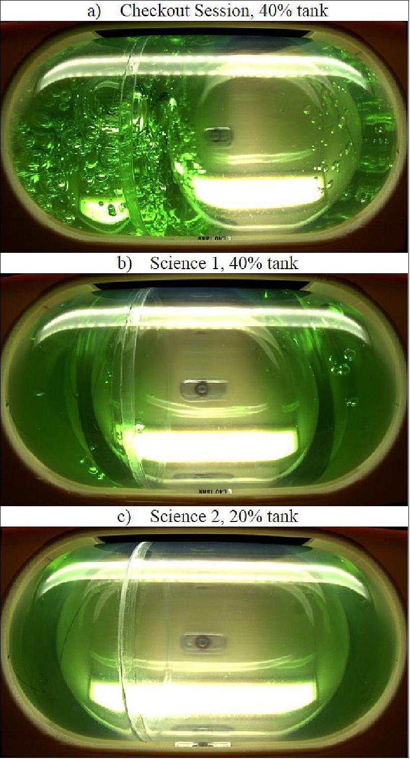
The next test session was called Science 1 as it would serve as the first session with gathering science data as the primary objective. For this session, a total of three maneuvers were developed to attempt to produce a better initial condition. The crew members running the session were instructed to try all three and determine which works best. The first maneuver involved accelerating the system along the principal (long) axis and quickly bringing it to a stop. The second method involved spinning the experiment about one of the SPHERES. Both of these methods were fairly effective but required a large amount of space which is not readily available on the ISS. The third method turned out to be the preferred method as it took less space and proved to be most effective. This method involved spinning the system about its center axis. When the crew members did this initialization maneuver by hand, the fluid would cleanly split in two and make a nice initial condition. Figure 21 illustrates the difference between a bad initial condition, as seen during the checkout session, and a good initial condition as seen after implementing the initialization maneuver.
Science 1 was a very productive session that used the 40% tank. This session successfully completed 11 runs. Several of these runs were completed with the light box removed so the crew members could monitor how well the initialization maneuvers worked. Once the fluid was properly initialized, the crew members were instructed to initiate the thruster firing sequence. A majority of the runs completed during this session involved thruster firings from the SPHERES.
Post processing of the data from science session 1 revealed that:
• The acceleration levels achieved by the thrusters on the SPHERES are simply too low to create any significant fluid motion. Since the validation of the CFD tools require fluid motion, the data quality from this session was rather low.
• The crew members were capable of pushing the system in a way that created interesting fluid motion in the tank. The higher acceleration levels achieved by manually moving the experiment created higher quality data.
Since the low levels of thrust from the SPHERES were determined to be insufficient to properly move the fluid in the tank, the following session was designed to include more runs with crew induced maneuvers.
Science 2 was the first session to use the 20% fill fraction tank, denominated L20, and the same settling principles found for the 40% tank (L40) were applied to this session, as shown in Figure 21c). It consisted of several tests under rotational, translational and pitching motions.
Science 3, performed with the L20 tank (20% fill fraction), contained a few specific maneuvers on satellite deployment issues.
Science 4 was focused on replicating the same maneuvers from Science 3, using the 40% tank instead.
As shown in Figure21a, b and c, no meniscus is visible in the tank, suggesting a fully wetted inner surface. This triggered particular interest to find the transition value of Bond number between a fully surface-tension dominated regime to an inertial-dominated regime, through the observation of the meniscus. During Science session 5, crew members were asked to perform maneuvers manually outside the slosh frame and provide visual feedback on the transition characteristics.
Mission Status
• September 11, 2020: Crew members aboard the International Space Station conducted scientific studies on fluid dynamics, durable coatings for spacecraft, and confocal microscope technology during the week of Sept. 7. 35)
- Now in its 20th year of continuous human presence, the space station provides a platform for long-duration research in microgravity and for learning to live and work in space. Experience gained on the orbiting lab supports Artemis, NASA’s program to go forward to the Moon and on to Mars.
- Turbulence in the tank: During this week, crew members conducted several runs of the FLUIDICS investigation. Sponsored by ESA (European Space Agency), this experiment uses three transparent, liquid-filled spheres to evaluate the phenomena of liquid sloshing and surface wave turbulence in a spacecraft fuel tank. A better understanding of sloshing may enable hardware designers to reduce its effects on guidance and precision of satellites and optimize satellite lifetime through improved fuel management. Observing surface wave turbulence in microgravity can provide insights into measuring the existing volume in a sphere – or, in other words, help more accurately determine how much fuel is in the tank. On Earth, gravity and surface tension affect turbulence, but microgravity allows scientists to focus only on the specific effects of surface tension.
• July 31, 2020: Satellites, launchers and many other spacecrafts have to carry liquid propellant in tanks, but if the tanks aren’t full this liquid sloshes around inside and can throw off the trajectory of the craft – similar to how a half-filled water bottle wobbles when thrown, except in microgravity. 36)
- A recently closed ESA GSTP (General Support Technology Program) activity with ArianeGroup, Germany, has taken advantage of an ongoing NASA experiment, to model exactly how partially filled liquid tanks can affect a spacecraft’s movement.
- The NASA experiment onboard the International Space Station uses two small flying robotic SPHERES with tiny thrusters to tow a liquid-filled capsule, attempting to control it in microgravity using software and pre-programmed trajectories.
- While this SPHERES experiment intends to improve our understanding of deorbiting objects, such as a stranded satellite, this information is also being fed to the ArianeGroup team, who are modelling how the capsule moves digitally and the best means to dampen any fluctuations from the planned route.
- The activity found that the goal of towing the liquid capsule in a pre-determined direction was only manageable by pulling the three bodies (two SPHERES, one slosh tank) along a straight line and, in fact, the sloshing liquid was advantageous when attempts were made to stabilize the uncontrolled tank motion. In fact it was found that the tether’s force has to go through the body’s centre of gravity since any deviation will disturb the flight direction. Being aware of this problematic may impose additional constraints on future tether concepts.
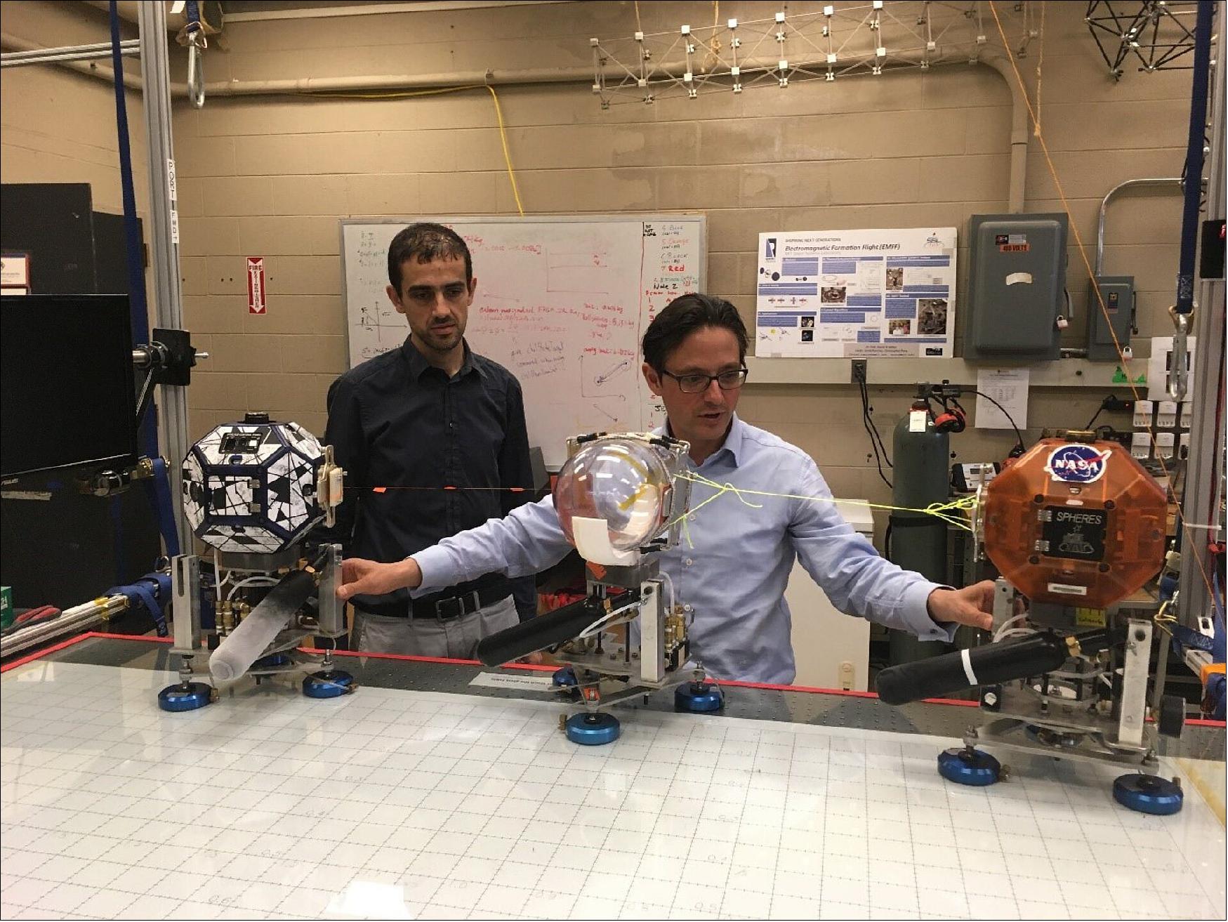
- Whether the tether was attached nearer to the tanks center of gravity, how slack the tether was and how much the tether jerked the tank when it was towing all require more experimentation, to determine what effect they truly had on the results.
- Further studies will also be necessary to determine how much damping is necessary to control a similar system, especially if the bodies are moving slowly relative to each other. If a tether jerks on an uncontrolled body it may eventually have a greater speed than the towing spacecraft, finally crashing into it. Using a liquid filled tank transferred part of the kinetic energy into fluid motion balancing the tether’s jerk and reducing the body’s velocity.
- Eventually, this digital model will be able to be scaled up to simulate launchers, satellites and any uncontrolled object which needs to be towed with a tether.
• January 31, 2018: NASA astronauts Joe Acaba and Mark Vande Hei brought out a pair of tiny satellites, also known as SPHERES (Synchronized Position Hold, Engage, Reorient, Experimental Satellites), for a run of the SmoothNAV experiment today. The study is researching how algorithms and sensors may help determine relative positions and velocities between spacecraft. 37)
- The crew set up the SPHERES work area to activate and check out the hardware and EXPRESS laptop computer (ELC) before conducting the SmoothNav experiment run. SmoothNav develops an estimation algorithm aggregating relative state measurements between multiple, small, and potentially differently instrumented spacecraft. The algorithm obtains the most probable estimate of the relative positions and velocities between all spacecraft using all available sensor information, including past measurements. The algorithm remains portable between different satellite platforms with different onboard sensors, adaptable in the case that one or more satellites become inoperable, and tolerant to delayed measurements or measurements received at different frequencies.
• March 17, 2017: The SPHERES investigation has become a popular project among astronaut crew of the International Space Station. For over ten years, the SPHERES Facility at NASA’s Ames Research Center in California’s Silicon Valley, has continued successful operations and delivery of impressive and increasingly complicated science to the ISS community. 38)
- In its eleventh year of operations, SPHERES starts 2017 by setting an all-time record of the most SPHERES Test Sessions with a seven-week period. Since January, SPHERES has performed nine Test Sessions, with four of them occurring in one week, back to back. Typical test sessions occur once every four to eight weeks, setting a precedent for operating SPHERES at a high pace. The nine test sessions required over 61 hours of test session time, with over 100 hours of crew time because some sessions utilized multiple crew. Five different investigations/experiments were performed over these nine sessions, each requiring special hardware configurations. Some investigations were thus run more than once or on multiple days. Four of the six ISS crew participated in these sessions.
- In January, the first three Test Sessions were spent completing a successful High School Zero Robotics (ZR) competition event.
- On February 1, four scientific investigations were conducted over two weeks, with two or more each day. During these Test Sessions, the SPHERES team collaborated with Payload Developer (PDs) and Principle Investigators (PIs) from MIT in Boston, Kennedy Space Center (KSC), and Airbus Defense in Houston. Code implementation, activity planning, crew procedures upgrades, and facility and hardware testing are some of the many tasks required to assure ISS and SPHERES Facility readiness for the successful operations of these test sessions.
- To date, the SPHERES team has conducted the following test sessions:
January 4, 2017: Zero Robotics Units Test
January 16, 2017: Zero Robotics Dry Run
January 27, 2017: Zero Robotics Finals event
January 31, 2017: SLOSH Tank Maneuver
February 1, 2017: SPHERES-Tether Science 1
February 2, 2017: SPHERES-Halo Checkout part 1
February 3 2017: SPHERES-Halo Checkout part 2
February 9, 2017: SPHERES-Docking Port Science 1B
February 14, 2017: SPHERES-Docking Port Science 1C.
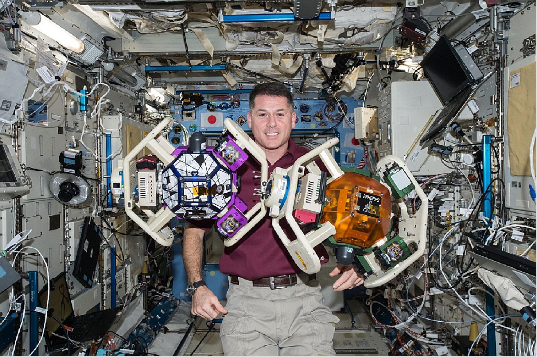
- Checkout of the SPHERES Halo hardware (Figure 24) was a significant milestone during test sessions. The SPHERES Halo is a six-sided, ring-shaped structure that is fastened around a SPHERES satellite and electrically connected to the VERTIGO avionics stack. Using a standardized interface and connector, a wide variety of peripherals can be connected to the satellite, increasing the capability and flexibility of SPHERES. These peripherals can be multiple Docking Ports for different assembly geometries, optical rangefinders, thermo-cameras, control moment gyroscopes, as well as robotic arms to provide grappling capabilities.
- During the six-weeks, two Docking Port science test sessions were conducted. A SPHERES Docking Port is an androgynous docking and berthing mechanism that allows two SPHERES satellites to autonomously align and rigidly connect. Docking Ports also feature cameras and fiducial markers, recognized by computer vision algorithms to assist the approach of the two satellites. The capability of assembling multiple SPHERES together helps simulate and develop missions where complex space structures are autonomously assembled and controlled using shared resources.
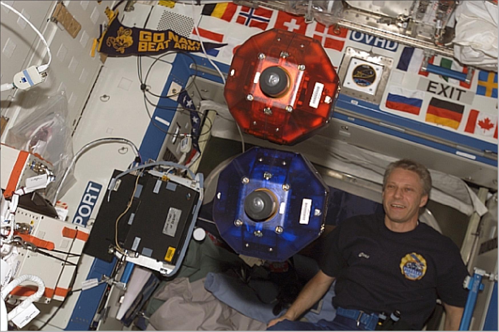
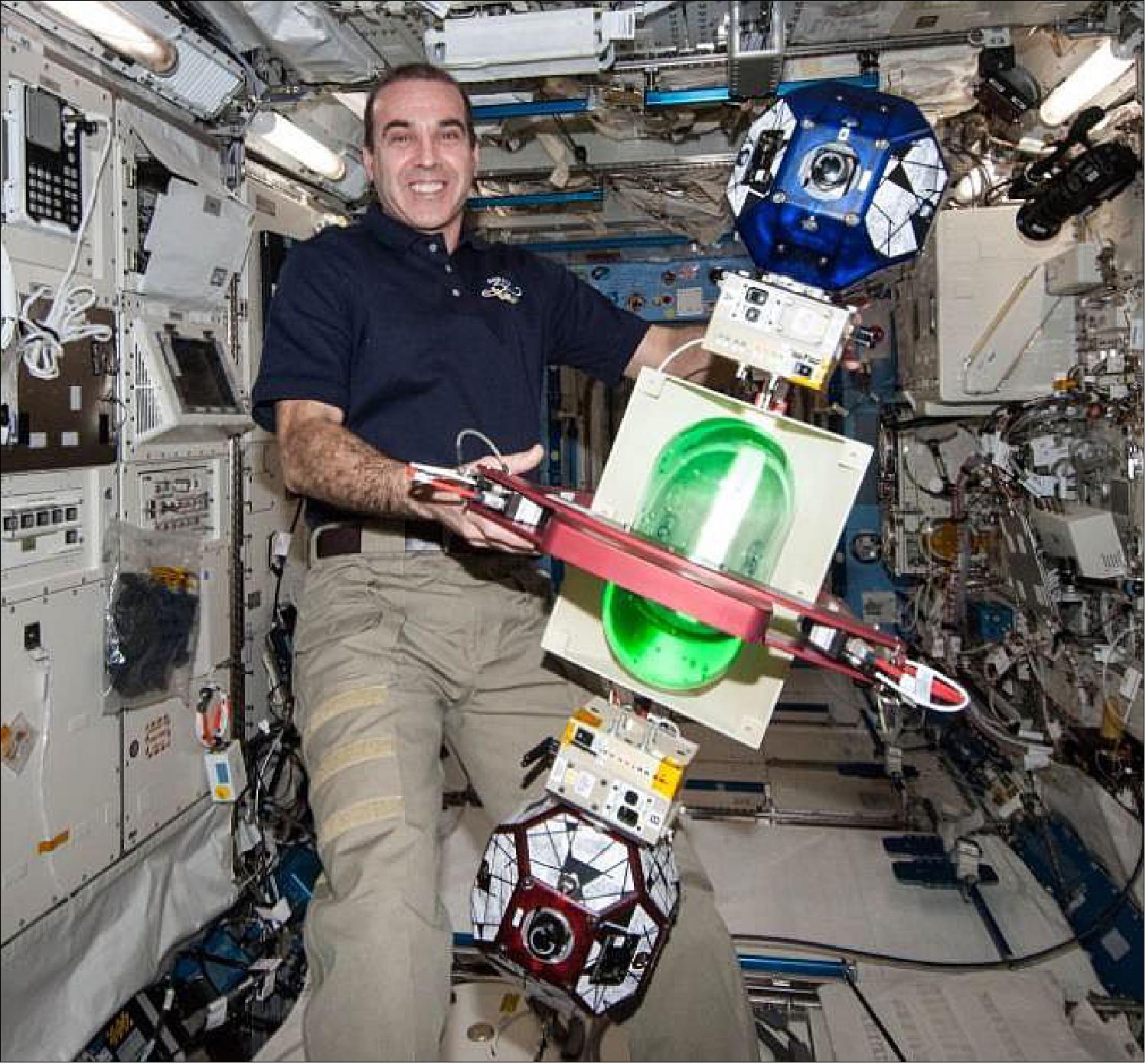
- With the conclusion of the three-year SPHERES-Slosh investigation, in 2016, came great popularity as additional maneuvers were developed and the use of only the tank without the SPHERES hardware. The SPHERES team still performs operations for these experiments. On January 31, 2017, ESA astronaut Thomas Pesquet (Figure 25) performed the recent Slosh exposed tank maneuvers. Although the mechanics of fluid dynamics in microgravity are still not well known, Slosh is helping to provide data of great interest to NASA and its industry partners, particularly the research team from KSC. The Slosh investigation will greatly improve our understanding of how propellants within rockets behave in order to increase the safety and efficiency of future vehicle designs. The Slosh team plans to launch two new tanks to the ISS with a unique internal liquid propellant coating to further study this phenomena and will conduct additional Test Sessions with these tanks without any other hardware.
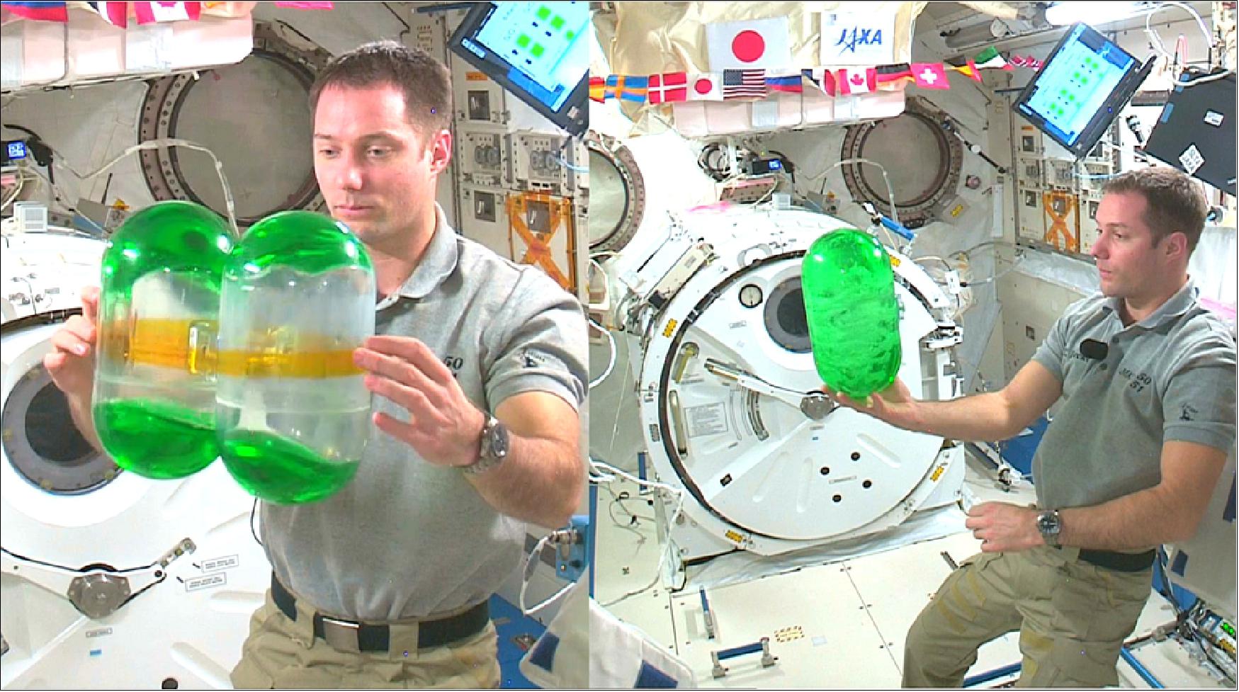
• December 16, 2016: Understanding the dynamics of tethering to capture loose objects and “space tug” chase vehicles in zero gravity will help meet the goals of the SPHERES Tether Demonstration project onboard the ISS. With this new capability the SPHERES team can improve computer programs and modeling needed for the SPHERES free-flying satellites to remove space debris and capture scientific samples from planetary objects on future deep space missions. The SPHERES Tether is a new integrated payload designed and developed by Airbus Defense and Space, in collaboration with NASA and MIT. 39)
- After reaching thorough research and development phases, the Tether hardware was launched April 8, 2016 on the SpaceX 8 mission to the ISS. On December 1, Expedition 50 crew members Commander Shane Kimbrough and ESA Astronaut Thomas Pesquet performed a successful SPHERES Tether Checkout test session with two different tethers - a nylon monofilament and a Kevlar thread. Several maneuvers were tested to measure the dynamic response of the tether being stressed longitudinally, and to assess the dynamics of the satellites being tugged from different angles. Kimbrough and Pesquet collected data from the main maneuvers in addition to several backup maneuvers and a real-time maneuver, which provided an additional point of view of the Tether system.
- Several objectives were met during this test session, including: 1) demonstration of hardware functionality; 2) accomplished six-degrees-of-freedom flight dynamics data as one tug satellite pulled a target satellite in different starting and control conditions; 3) assessment of the impact of tether material, tension and torque between tethered satellites. A total of 31 maneuvers were tested and high resolution videos were recorded of the experiment which were augmented by data from accelerometers, gyroscopes, and positioning sensors of each SPHERES satellite. In addition to the efficiency of running the maneuvers, Kimbrough and Pesquet worked together to manually release the satellites, and command them through a user interface on a laptop. These tasks were critical to the successful completion of each run.
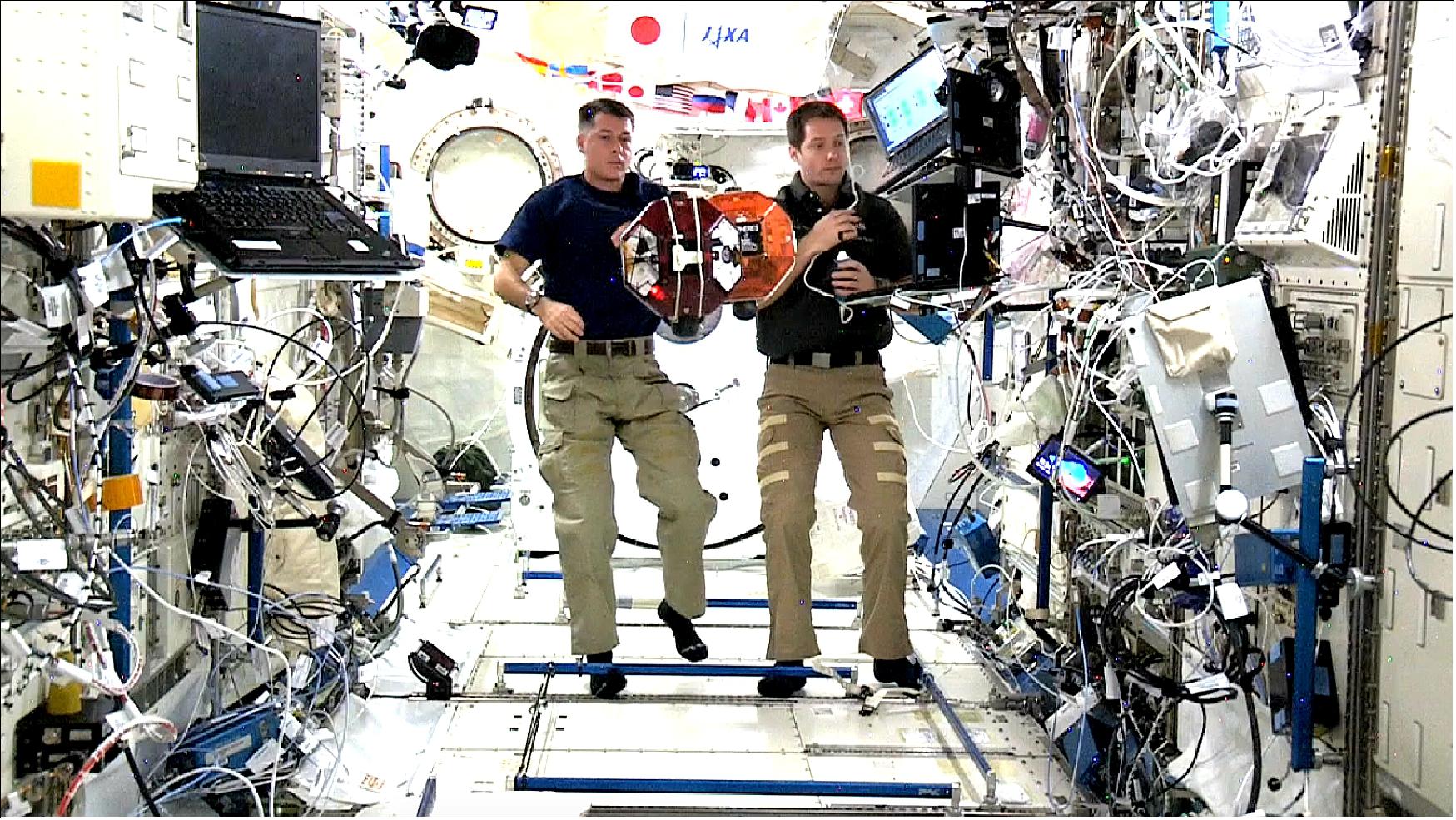
- After release by the crew, the satellites went into a self-localization and stabilization mode for 30 seconds, followed by a simple computer key stroke to enter the tether dynamics phase of each maneuver; in some runs, this operation happened in mid run, which enhanced the control parameters of the maneuver. The presence of the tether between the two SPHERES in combination with the impulsive thrusting of the SPHERES had the potential to introduce a periodic “bouncing” that could’ve made the initial conditions of the maneuvers uncertain. By observation, the crew members could determine when the test was ready to start, or if any adjustments were needed.
- Over the past year, it was discovered that one of the 12 thrusters on the "Red" SPHERES satellite was compromised. These maneuvers for accuracy and stability during release of the satellites enabled improved science and fuel (CO2) consumption for "Red."
- With the successful data collection and achieving their test objectives, the SPHERES team is confident that data analysis will enable future Tether science with SPHERES satellites and validation of computer simulations of tethered space systems.
• September 28,2016: A small drone taught itself to judge distances using only one eye during trials aboard the International Space Station, ESA-backed researchers have reported. Although humans can effortlessly estimate distances with a single eye, robots still lack this capability. “It is a mathematical impossibility to extract distances to objects from one single image, if the object has not been encountered before,” explains Guido de Croon from Delft University of Technology, one of the investigators. “But if we recognize something to be a car, then we know its physical characteristics, and we can use that information to estimate its distance from us. A similar logic is what we wanted the drone to learn during our experiment.” 40)
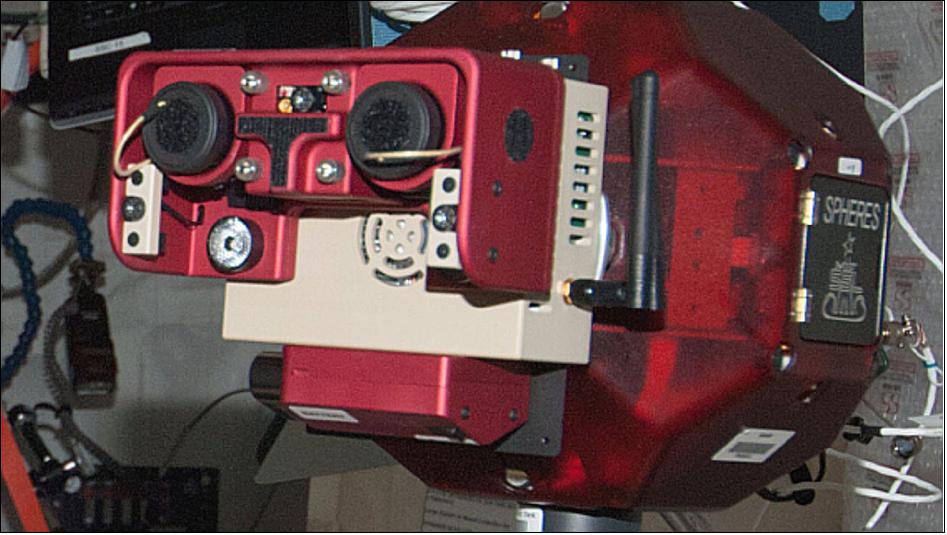
- One of the SPHERES drones resident in the Space Station was pressed into service for testing. With 12 carbon dioxide gas thrusters enabling rotation and movement in all direction, the bowling ball-sized SPHERES are essentially free-floating mini-spacecraft within the Station, used for testing a wide variety of technology.
- For this test, a drone began navigating inside the JEM (Japanese Experimental Module while recording stereo vision information from its two camera ‘eyes’ (Figure 28). It then began to learn about the distances to walls and nearby obstacles so that when its stereo camera was switched off, it could then begin autonomous exploration using only a single camera.
- Operating in weightlessness, with no favored up or down direction, added to the challenge. However, the experiment demonstrated that machine learning would indeed allow the normally stereo-viewing drone to recover from the loss of one camera. The self-supervised learning software had previously been tested thoroughly at the TU Delft CyberZoo – a research lab for flying and walking robots – using quadcopters.
- The experiment, presented on 27 September at the IAC (International Astronautical Congress) in Guadalajara, Mexico, marked an important step in an ongoing research effort based on advanced artificial intelligence concepts, in collaboration between ESA, MIT (Massachusetts Institute of Technology) and the Micro Air Vehicles Lab of the Delft University of Technology.
- “It was very exciting to see a drone in space learning using cutting-edge artificial intelligence methods for the very first time,” explains Dario Izzo, coordinating the research contribution from ESA’s Advanced Concepts Team. “Our approach, based on self-supervised learning, has a high degree of reliability and helps drone autonomy. A similar learning approach was successfully applied to self-driving cars, a task where reliability is also of paramount importance.”
- Leopold Summerer, heading the Advanced Concepts Team, adds: “This is a further step in our quest for truly autonomous space systems, which are increasingly in demand for deep-space exploration, complex operations, for reducing costs, and increasing capabilities and science opportunities.”
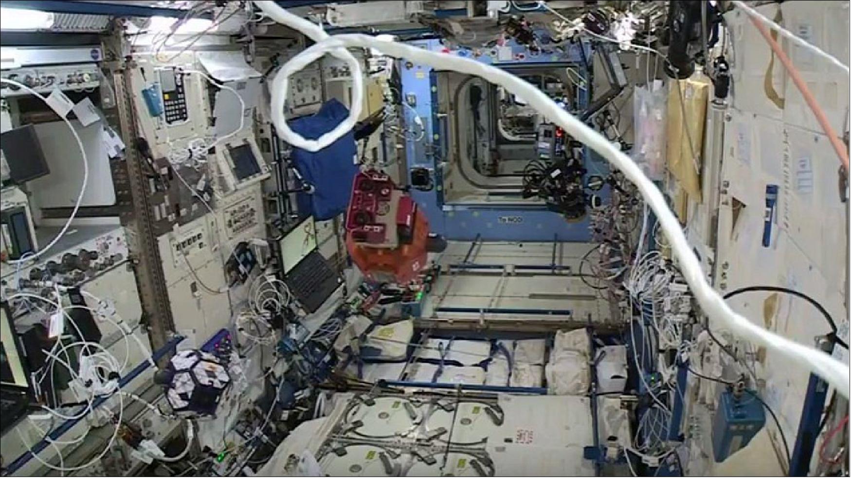
• January 2015: Inspired by ESA’s Rosetta mission and the upcoming NASA OSIRIS-Rex mission, Zero Robotics finalists were given the task to simulate imaging a virtual asteroid on the International Space Station on Jan. 16, 2015. Secondary-school students from across Europe controlled miniature satellites on the ISS in a competition to get the best images. 41)
- The Space Station was turned into a playing field for the finals. The ultimate robot game challenged youngsters to write algorithms that controlled the Spheres, short for Synchronized Position Hold, Engage, Reorient, Experimental Satellites.
- On January 16, 2015, was the fifth time European contenders ran their commands in space, and each year the competition has grown. Over 140 European students joined the US, Mexican and Russian competitors, writing code to image the celestial body whilst maneuvering out of a damaging virtual solar flare.
- European and Russian finalists met at the ESA Technical Center in the Netherlands to follow the competition live from space. The US and Mexican teams were connected via video conference at the MIT (Massachusetts Institute of Technology).
- On the Station, ESA astronaut Samantha Cristoforetti, NASA astronaut Butch Wilmore and cosmonaut Yelena Serova monitored the robotic battle. ESA astronaut Paolo Nespoli and NASA crew mate Cady Coleman were also present at ESTEC and MIT respectively, cheering the teams on.
- Each finalist alliance was composed of teams mostly from US and ESA member states. This year saw the first time participation of Russian and Mexican teams, making Zero Robotics a truly international endeavor.
- The contest started last year with online rounds of increasing difficulty. Teams faced real-world challenges: they had to deal with loss of signal, exhausted batteries and tight deadlines. Long nights of programming and lots of discussions between the teams to decide tactics are all part of the game.
- The championship prize went to the alliance called LakeElevenVadars – an alliance including “Cora’s Eleven”, from Italy who attribute their win to having as many strategic and coding options available to them as possible, until the very last minute before submission deadline.
- In second place, first time participants Zanneio Stardust team from Greece. Together with their US team mates, BACON and BRRobotics, they formed formidable opponents throughout the competition and lost in the finals by a hair’s breadth.
• July 2014: The Cygnus CRS Orb-2 mission to the ISS (launch on July 13, 2014) included also two Google prototype Project Tango smartphones, that astronauts will attach to the SPHERES for technology demonstrations inside the space station. By connecting a smartphone to the SPHERES, it becomes "Smart SPHERES, " a more "intelligent" free-flying robot with built-in cameras to take pictures and video, sensors to help conduct inspections, powerful computing units to make calculations and Wi-Fi connections to transfer data in real time to the computers aboard the space station and at mission control in Houston. 42)
- In a two-phase experiment, astronauts will manually use the smartphones to collect visual data using the integrated custom 3-D sensor to generate a full 3-D model of their environment. After the map and its coordinate system are developed, a second activity will involve the smartphones attached to the SPHERES, becoming the free-flying Smart SPHERES. As the free-flying robots move around the space station from waypoint to waypoint, utilizing the 3-D map, they will provide situational awareness to crewmembers inside the station and flight controllers in mission control. These experiments allow NASA to test vision-based navigation in a very small mobile product.
- Ultimately it is the hope of researchers that these devices will perform housekeeping-type tasks, such as video surveys for safety and configuration audits, noise level measurements, air flow measurements, and air quality measurements, that will offset work the astronauts currently perform.
• March 11, 2014: In a breakthrough that will help make it possible for astronauts and robots to work together in deep space, researchers at the Lockheed Martin ATC (Advanced Technology Center) in Palo Alto, CA, working with NASA astronauts aboard the International Space Station, have demonstrated coordinated control of robots in space by astronauts in space and operators on the ground. The breakthrough is the first-ever demonstration of such collaborative teleoperations. The maneuvers create new opportunities to extend the reach of human and robotic missions in Earth orbit and beyond. 43)
Astronaut Karen Nyberg and ATC engineer Humberto Ormeno used an ATC-developed, 3D user interface to command NASA’s SPHERES robots on the space station. Inside the space station, the robots were commanded in “follow-the-leader” exercises and simulated approach-and-docking maneuvers, like those required for in-space assembly of large space structures and asteroid exploration. There is also flexibility within the system, meaning automated control of one or more robots can be combined with manual control of another.
Remote commanding of robots in space, or teleoperation, poses several unique challenges. Commands and telemetry can take one to three seconds to travel between space and the ground via satellite relays, forcing remote operators to predict the effects of their actions using old data. Delicate components designed for weightlessness can be damaged by accidental collisions or even exhaust gases produced by other satellites, so safe maneuvering is essential. The work on the space station is demonstrating how to deal with the time delays associated with signal transfer from the ground.
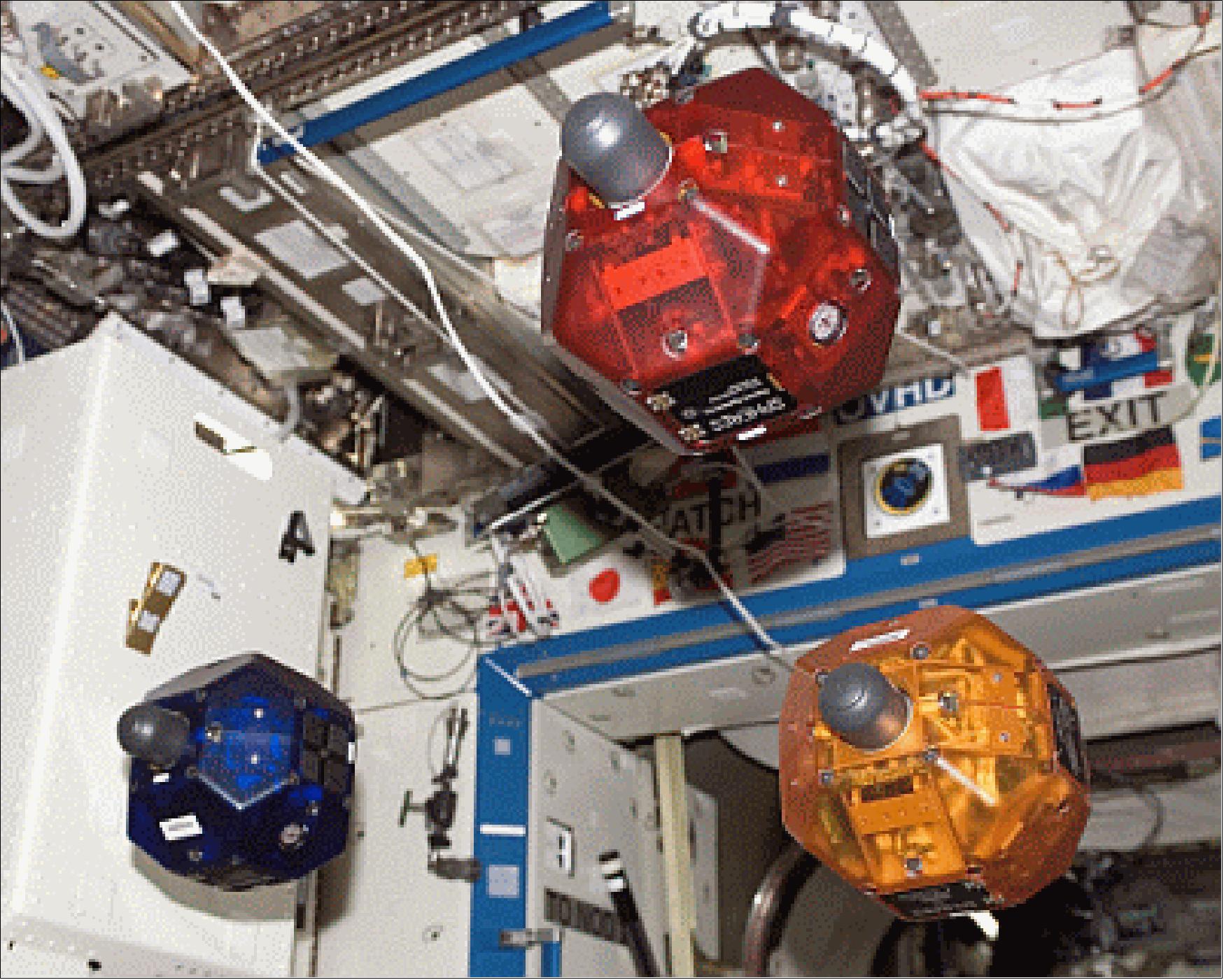
• Feb. 25, 2014: The SPHERES satellites have been flying aboard the International Space Station since 2003. Powered by AA batteries, the satellites act as free-flying platforms that can accommodate various mounting features and mechanisms in order to test and examine the physical or mechanical properties of materials in microgravity. 44)
- The DoD “SPHERES-Rings” investigation is the first demonstration of electromagnetic formation flight in microgravity, as well as of wireless power transfer in space. The study installs highly advanced rings to existing SPHERES. The crew places the rings around an individual satellite, consisting of resonant coils, coil housing with fans, batteries and support structure hardware. The Rings project demonstrates the use of electromagnetic coils to maneuver individual SPHERES with respect to one another. The current running through the ring of coils controls the satellites, so that two ring-outfitted SPHERES are able to attract, repel, and rotate.
- Using electrically generated forces and torques is preferable to using fuel, since electricity can be generated by solar panels, but once fuel is expended, the mission is generally over. The research goals for SPHERES-Rings include enhanced attitude control performance between separate satellites and the possibility of more efficient power transfer at a distance. Adding an efficient way to transfer power between SPHERES may alleviate the need for alternate power sources. The wireless power transfer experiment establishes the hardware necessary for potential future powering of space and urban robotics and enhanced communications systems in space, on land, or underwater.
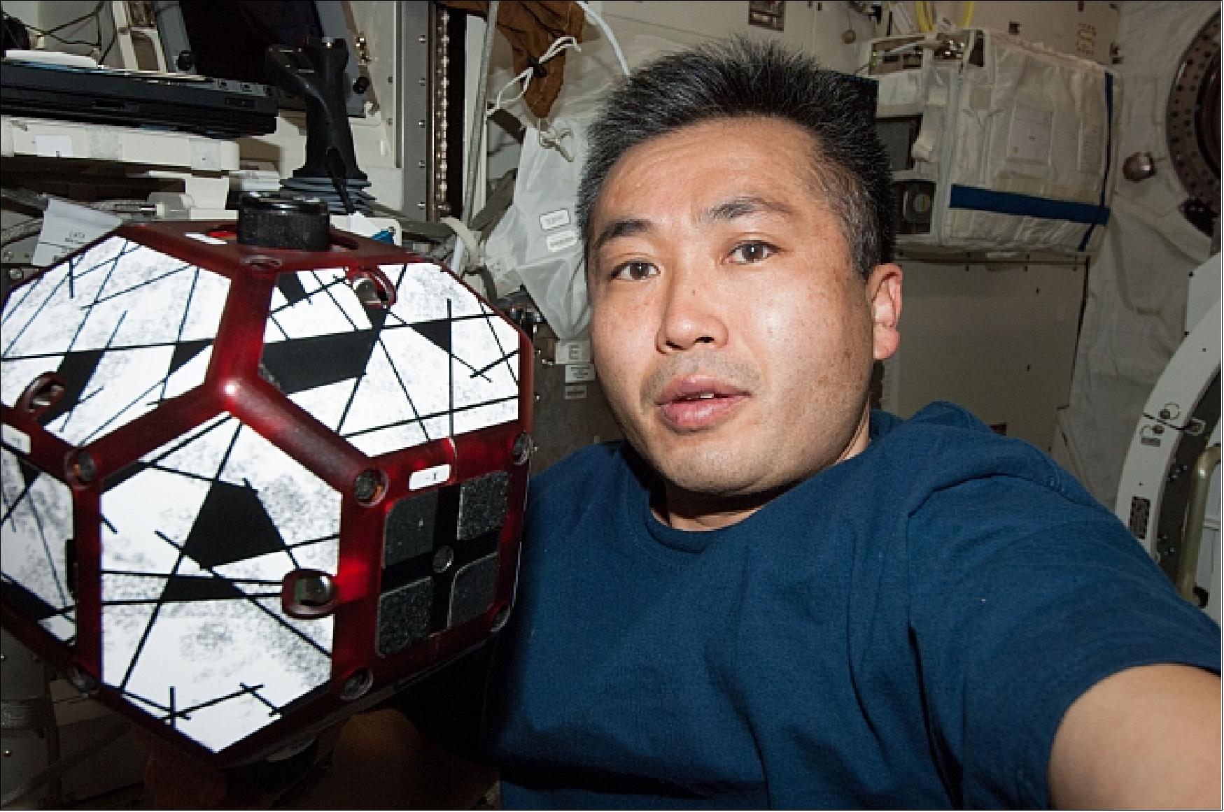
• Feb./March 2013: Inside the JEM/Kibo Laboratory, NASA astronaut Thomas Marshburn worked for the first time with the bowling-ball-sized free-flying satellites SPHERES-VERTIGO which were ground commanded. 45) 46) 47)
- The SPHERES-VERTIGO investigation uses the SPHERES platform on ISS and is designed to demonstrate stereo visual inspection in order to assess close proximity inspection and navigation, including dead reckoning navigation and fiducial-assisted (i.e., navigational tracking marker assisted) navigation and inspection.
- The SPHERES-VERTIGO investigation software incorporates computer vision based navigation and mapping algorithms capable of building a three-dimensional map of another object and performing relative navigation solely by reference to this three-dimensional model.
- In order to test these algorithms, hardware upgrades to the SPHERES facility satellites includes cameras, an upgraded processor, a high-speed communications system and additional batteries.
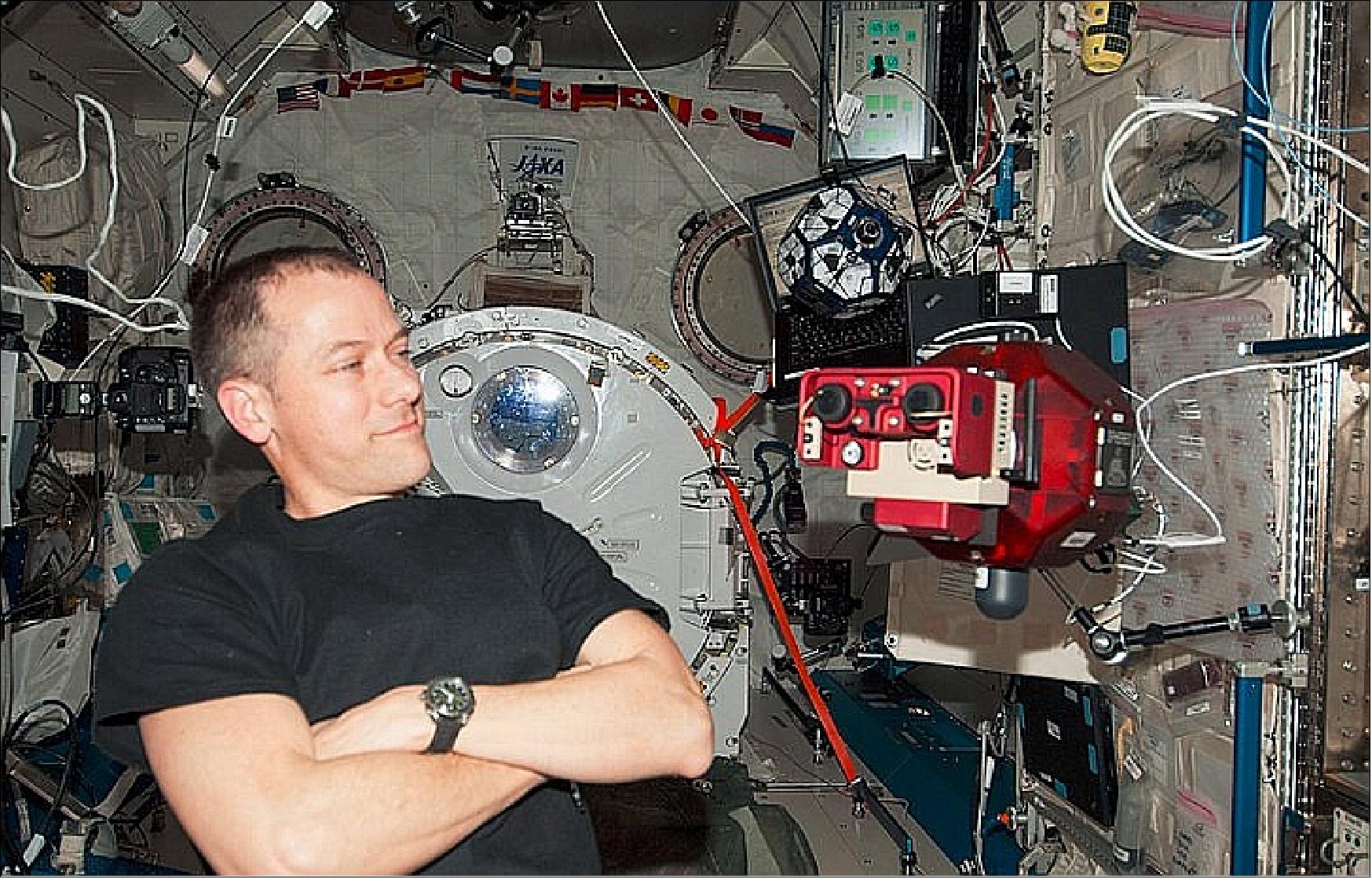
• In early 2012, the SPHERES satellites are operational (i.e., they are being used for tests) on ISS (Ref. 52). - So far, MIT has held 32 test sessions onboard the ISS covering research topics such as rendezvous and docking, formation flight, decentralized control, satellite reconfiguration, inertial navigation and other research areas. Additionally, the SPHERES satellites have been used for national and international STEM programming competitions where middle and high school students have programmed the SPHERES satellites that are on-orbit.
• The third annual Zero-Robotics SPHERES Challenge for high school students was conducted at MIT on January 23, 2012. High school student teams from the USA and Europe competed in this event. NASA sponsored the Zero Robotics SPHERES Challenge in partnership with the DARPA (Defense Advanced Research Projects Agency) and MIT. The competition aligns with the agency’s goal of encouraging students to study and pursue careers in STEM (Science, Technology, Engineering and Mathematics). 48) 49) 50) 51)
The objective for this year's challenge: students were given a “mission” to program robots to look for, mine (extracting minerals) and return alternative energy from fictitious asteroids in deep space. They were given coordinates for virtual asteroids located within the ISS and then had to develop computer codes to make a robot perform using various strategies, each of which earned a certain number of points. The free-floating satellites (2 SPHERES) could collect tools if needed and start mining on one of two virtual asteroids.
For the past few months, student teams had been testing their codes in computer simulations, maneuvering virtual robots and competing against other teams in online games. The finalists — 38 teams with the best simulation scores — assembled at MIT on January 23, 2012 for a chance to watch their codes play out in real robots on the ISS. Prior to the competition, NASA had uploaded the software developed by the finalist student teams onto SPHERES in the ISS.
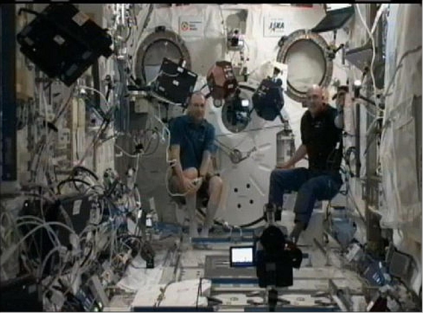
Once NASA successfully connected the MIT auditorium with the ISS, a large screen at the front of the hall projected a live view from inside the station. Astronaut Don Pettit, onboard the ISS, responded, “We hear you loud and clear, MIT.” - Don Pettit and André Kuipers had set up the individual matches in Japan’s Kibo laboratory on the Space Station and enjoyed the spectacle. They presided over the event and gathered data from the student-controlled SPHERES flight programs after each phase of the competition.
Despite a few glitches in the video feed, most teams were able to watch their algorithms in action. During each match, both a red and a blue SPHERE began their missions simultaneously, slowly circling each other and moving about the module according to their preprogrammed trajectories.
The teams “Alliance Rocket“ from the United States and virtual participants “Alliance CyberAvo” from Europe were named the winners in the third annual Zero Robotics SPHERES Challenge.
A total of 38 teams participated in the SPHERES event. Both winning groups consisted of three teams:
- The teams that made up “Alliance Rocket” were Team Rocket, River Hill High School, Clarksville, Maryland; Defending Champions, Storming Robots, Branchburg, New Jersey; and SPHEREZ of Influence, Rockledge High School/Brevard County, Florida.
- “Alliance CyberAvo” consisted of CyberAvo, I.T.I.S. Amedeo Avogrado, Turin, Italy; Ultima, Kaethe Kollwitz Oberschule, Berlin, Germany; and Lazy, Heinrich Hertz Gymnasium, Berlin, Germany.
• In November 2011, the SPHERES satellites were upgraded with “off-the-shelf” smartphones by using an “expansion port” the MIT team designed into each satellite. Since the SPHERES were originally designed for a different purpose, they needed some upgrades to become remotely operated robots. By connecting a smartphone, the project can immediately make SPHERES more intelligent. With the smartphone, the SPHERES will have a built-in camera to take pictures and video, sensors to help conduct inspections, a powerful computing unit to make calculations, and a Wi-Fi (Wireless Fidelity) connection that the project will use to transfer data in real-time to the space station and mission control. - n order to make the smartphones safer to use onboard the station, the cellular communications chips were removed, and the lithium-ion battery was replaced with AA alkaline batteries.
Until recently, the SPHERES tests used pre-programmed algorithms to perform specific functions. The space station is just the first step to using remotely controlled robots to support human exploration.
By testing the SPHERES satellites, NASA can demonstrate how the smart SPHERES can operate as remotely operated assistants for astronauts in space. NASA plans additional tests in which the compact assistants will perform interior station surveys and inspections, along with capturing images and video using the smartphone camera. Additional goals for the mission include the simulation of free-flight excursions, and possibly other, more challenging tasks. 52)
• SPHERES has operated aboard the ISS since May 2006. The long-duration program continues to provide valuable information for scientists at the MIT Space Systems Laboratory and an array of guest scientists from other institutions. The major milestones of 2006 were achieved in the advancement and demonstration of docking algorithms.
• Throughout 2007 and 2008 the research SPHERES expanded to include substantial research in formation flight algorithms (Table 5). 53) 54)
TS (Test Session) | Date | Science configuration/goal |
7 | March 24, 2007 | 2-Sat Lost-in-Space, 3-Sat Formation Flight |
8 | April 27, 2007 | 3-Sat Formation Flight |
10 | December 12, 2007 | 2-Sat Formation Initialization & Scatter |
11 | January 27, 2008 | 2-Sat Formation Initialization & Scatter |
12 | August 30, 2008 | 2-Sat Spiral Formations |
13 | September 27, 2008 | 3-Sat Collision Avoidance |
14 | Oct/Nov. 2008 | 3-Sat Simulated comm & thruster failures, 2-Sat Spiral Formations |
Three-satellite formation flight experiments began in TS7 with basic circular formations. The research then grew into two main areas: control of rotating formations and algorithms to provide autonomy for distributed satellite systems. An extensive set of algorithms was developed based on the need for satellite formations to reconfigure in response to operational goals and the status of individual satellites.
The SPHERES developments include tasks on four main areas:
• Imaging maneuvers: creation of circles and spirals to simulate the motions of potential separated spacecraft radar/telescopes.
• Formation acquisition: algorithms to initialize a formation from random initial conditions, including “Lost-in-space” algorithms, optimally joining an existing formation, and random selection of a formation leader.
• Formation maintenance: geometry reconfiguration, low-level collision avoidance, use of different sensor information, and changing between relative and absolute frames of reference.
• Fault detection and recovery: reconfiguration after a (simulated) satellite failure (sensors, actuators, and/or communications), scattering of operational satellites to avoid a failed satellite.
The 2007 and 2008 SPHERES formation fight tests concentrated on imaging maneuvers and autonomy algorithms. The imaging maneuvers used a wide range of controllers: PID (Proportional Integral Derivative), LQR (linear Quadratic Regulator), and cyclic pursuit. The use of basic PID controllers in circles was sufficient. But LQR controllers did not provide acceptable performance in spirals, exposing the need to use more complex controllers as the dynamics of spirals did not prove to be a simple extension of circular motion. The use of the decentralized controller resulted in the best performance to follow a spiral path (Ref. 53).
The autonomy algorithms covered a wide range of possible actions which must be taken by a distributed satellite system. Formation initialization from random deployment conditions tests allowed the team to identify multiple potential problems which would cause an algorithm to fail; these issues are sometimes directly related to the algorithm (e.g. potentially having no formation “leader”) and also from other parts of the satellite (e.g. loosing communications).
The lessons learned from the development of scatter maneuver algorithms include the somewhat obvious need to fully identify your surroundings, but also the importance of a scatter maneuver to dynamically determine the scatter direction. All satellites should move in opposite directions from each other, rather than move to a pre-determined “safe” location.
The collision avoidance tests demonstrated the ability to use a low-overhead process to enable this autonomous behavior on spacecraft systems. The tests have provided initial data to fully understand the empirical relationship between operational noise (i.e., deviations from an ideal path) and the “safety” box around a physical system.
The SPHERES team proposed two different methods for a formation flight system to recover from potential failures of one of the satellites. For communications failure, where the failed satellite is expected to be able to stop its motion, the suggested recovery is to change the plane of the formation. For thruster failures, the team suggests that a scatter maneuver is necessary to safeguard the operational satellites. The thruster failure simulation test demonstrated the validity of the scatter maneuver for this type of failure.
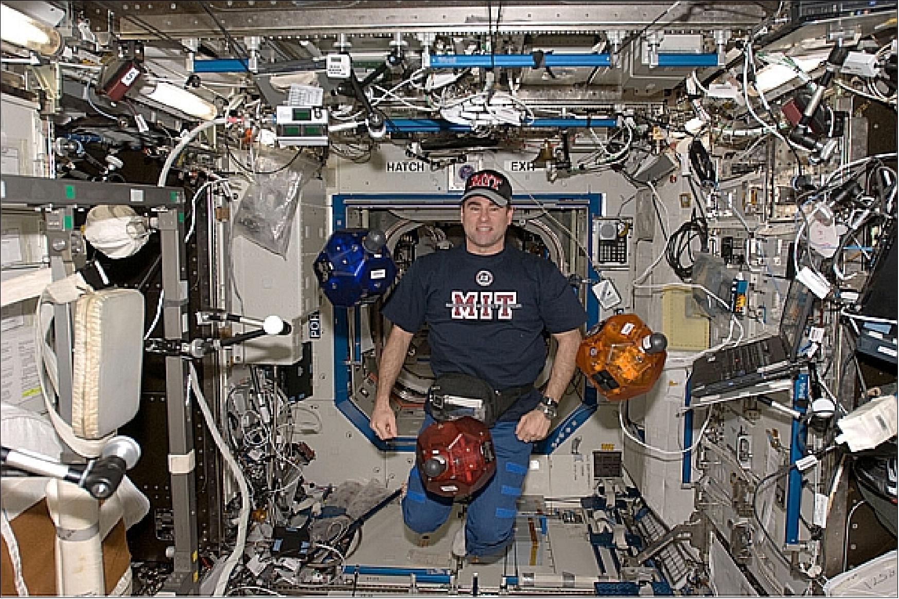
• SPHERES’s Test Session 12 was performed on August 30, 2008, onboard the International Space Station by the NASA Astronaut Greg Chamitoff. This Test Session included the Continuous Spiral Maneuver Tests. The visual inspection of the real video provided by NASA on the same day of the test session, proved the correct behavior of the trajectory planning algorithm and the implementability of these kind of coordinated trajectories in space.
References
1) S.-J Chung, D. Adams, A. Saenz-Otero, E. Kong; D. W. Miller, D. Leisawitz, E. Lorenzini, S. Sell, “SPHERES Tethered Formation Flight Testbed: Advancements in Enabling NASA's SPECS Mission,” Proceedings of SPIE Astronomical Telescopes and Instrumentation Symposium, Orlando, FLA, May 2006, SPIE paper 6268-11, `Advances in Stellar Interferometry,' URL: https://web.archive.org/web/20120619192353/http://ssl.mit.edu:80/spheres/library/spie_tether_2006.pdf
2) A. Saenz-Otero, D. Miller, “The SPHERES ISS Laboratory for Rendezvous and Formation Flight,” 5th International ESA Conference on Guidance Navigation and Control Systems, Frascati, Italy, Oct. 22-25, 2002, SP-516
3) D. W. Miller, E. M. C. Kong, A. Saenz-Otero, “Overview of the SPHERES Rendezvous and Docking Laboratory on the International Space Station,” Proceedings of the 26th AAS Conference on Guidance and Control, Breckenridge, CO, Feb. 5-9, 2003, Vol. 113, Advances in the Astronautical Sciences, Edited by I. J. Gravseth and R. D. Culp, AAS-03-013, pp. 155-169
4) S.-J. Chung, E. M. Kong, D. W. Miller, “Dynamics and Control of Tethered Formation Flight Spacecraft Using the SPHERES Testbed,” Proceedings of the AIAA Guidance, Navigation, and Control Conference and Exhibit, San Francisco, CA, USA, Aug. 15-18, 2005, AIAA 2005-6089, URL: https://web.archive.org/web/20170810202504/http://ssl.mit.edu/spheres/library/gnc2005tether.pdf
5) https://web.archive.org/web/20190326200630/http://ssl.mit.edu:80/spheres/index.html
6) A. Saenz-Otero, D. W. Miller, “Using ISS to develop telescope technology,” URL: https://web.archive.org/web/20170922050355/http://ssl.mit.edu/spheres/library/ISS.pdf
7) D. Miller, D. Newman, J. de Luis, “Synchronized Position, Hold, Engage, and Reorient Experimental Satellites (SPHERES), Test Equipment Data Package,” March 23, 2000
8) A. Saenz-Otero, D. Miller, “SPHERES: a platform for formation-flight research,” Proceedings of the SPIE, Vol. 5899, pp. 230-240 (2005), ``UV/Optical/IR Space Telescopes: Innovative Technologies and Concepts II,' San Diego, CA, August 2005, URL: https://web.archive.org/web/20180721221244/http://ssl.mit.edu/spheres/library/SPH.pdf
9) J. Enright, M. Hilstad, A. Saenz-Otero, D. Miller, “The SPHERES Guest Scientist Program: Collaborative Science on the ISS,” Proceedings of 2004 IEEE Aerospace Conference, Big Sky, MT, March 6-13, 2004
10) S. W. Sell, S. E. Chen, “SPHERES: Design of a Formation Flying Testbed for ISS,” Proceedings of IAF, 34th COSPAR Scientific Assembly, The Second World Space Congress, Oct, 10-19, 2002, Houston, TX, USA
11) A. Chen, A. Saenz-Otero, M. Hilstad, D. Miller, “Development of Formation Flight and Docking Algorithms Using the SPHERES Testbed”, 15th Annual AIAA/USU Conference on Small Satellites, Utah State University, Logan, UT, August 13-26, 2001, SSC01-VIIIa
12) D. Miller, A. Saenz-Otero, J. Wertz, A. Chen, G. Berkowski, C. Brodel, S. Carlson, D. Carpenter, S. Chen, S. Cheng, D. Feller, S. Jackson, B. Pitts, F. Perez, J. Szuminski, S. Sell, “SPHERES: A Testbed For Long Duration Satellite Formation Flying In Micro-Gravity Conditions,” Proceedings of the AAS/AIAA Space Flight Mechanics Meeting,, Clearwater, FL, USA, Jan. 23-26, 2000, AAS 00-110, URL: https://web.archive.org/web/20180521194740/http://ssl.mit.edu/spheres/library/AAS-AIAA.pdf
13) https://web.archive.org/web/20170829012008/http://ssl.mit.edu/spheres/library/SPHERES_0-1-2_SDP_A.pdf
14) D. Berkovitz, E. Kong, D. Miller, “System Identification of the SPHERES Autonomous Rendezvous and Docking Testbed,” Space 2003, 23 - 25 September 2003, Long Beach, CA, USA, AIAA 2003-6385
15) R. Lim, D. Miller, “Staged Attitude-Metrology Pointing Control and Parametric Integrated Modeling for Space-based Optical Systems,” Thesis at MIT, May 2006, URL: https://web.archive.org/web/20160402110542/http://ssl.mit.edu/publications/theses/SM-2006-LimRyan.pdf
16) E. M. Kong, A. Saenz-Otero, S. Nolet, D. S. Berkovitz, D. W. Miller, S. W. Sell, “SPHERES as a Formation Flight Algorithm Development and Validation Testbed: Current Progress and Beyond,” URL: https://web.archive.org/web/20160702035809/http://ssl.mit.edu/spheres/library/SPHERESFFPaper72.pdf
17) Amer Fejzic, Simon Nolet, Louis Breger, Jonathon P. How, David W. Miller, “Results of SPHERES Microgravity Autonomous Docking Experiments in the Presence of Anomalies,” Proceedings of the 59th IAC (International Astronautical Congress), Glasgow, Scotland, UK, Sept. 29 to Oct. 3, 2008, IAC-08.C1.5.1
18) Simon Nolet, Alvar Saenz-Otero†, David W. Miller, Amer Fjezic, “SPHERES Operations Aboard the ISS: Maturation of GN&C Algorithms in Microgravity,” Proceedings of the 30th Annual AAS Guidance and Control Conference, Breckenridge, CO, USA, Feb. 3-7, 2007, AAS 07-042
19) http://science.nasa.gov/headlines/y2006/01jun_spheres.htm
20) https://web.archive.org/web/20190329100346/http://ssl.mit.edu/spheres/news.html
21) J. Enright, M. Hilstad, A. Saenz-Otero, D. Miller, “The SPHERES Guest Scientist Program: Collaborative Science on the ISS,” IEEE Aerospace Conference 2004, Big Sky, Montana, March 6-13, 2004, Paper No 1296
22) A. Saenz-Otero, D. W. Miller, “Initial SPHERES Operations Aboard the International Space Station,” Proceedings of the 6th IAA Symposium on Small Satellites for Earth Observation, Berlin, Germany, April 23 - 26, 2007
23) M. O. Hilstad, J. P. Enright, A. G. Richards, “The SPHERES Guest Scientist Program,” MIT documentation, Oct. 29, 2003, URL: https://web.archive.org/web/20180915101537/http://ssl.mit.edu/spheres/gsp/
24) D. P. Scharf, F. Y. Hadaegh, S. R. Ploen. “A Survey of Spacecraft Formation Flying Guidance and Control. Part I: Guidance,” Proceedings of the American Control Conference, Vol. 2, pp. 1733-1739, June 4-6, 2003, Denver, CO, USA
25) G. S. Aoude, J. P. How, D. W. Miller, “Reconfiguration Maneuver Experiments Using the SPHERES Testbed Onboard the ISS,” Proceedings of the 3rd International Symposium on Formation Flying, Missions and Technology, ESA/ESTEC, Noordwijk, The Netherlands, April 23-25, 2008
26) Alvar Saenz-Otero, Jacob Katz, Swati Mohan, David W Miller, Gregory E Chamitoff, “ZERO-Robotics: A Student Competition aboard the International Space Station,” Proceedings of the 2010 IEEE Aerospace Conference, Big Sky, MT, USA, March 6-13, 2010
27) Brent E. Tweddle, Elias Müggler, Alvar Saenz-Otero, David W. Miller, “The SPHERES VERTIGO Goggles:Vision based mapping and localization onboard the International Space Station,” Proceedings of i-SAIRAS (International Symposium on Artificial Intelligence, Robotics and Automation in Space), Turin, Italy, Sept. 4-6, 2012, URL: http://robotics.estec.esa.int/
i-SAIRAS/isairas2012/Papers/Session%204B/04B_02_tweddle.pdf
28) Brent E. Tweddle, “SPHERES VERTIGO Program: Vision Based Navigation Research onboard the International Space Station,” IEEE IRCA (International Conference on Robotics and Automation), Shanghai, China, May 9-13, 2011, URL: http://ewh.ieee.org/conf/icra/
2011/workshops/SpaceRobotics/abstracts/Abstract_Tweddle.pdf
29) Alvar Saenz-Otero, “SPHERES - Maturation of Autonomous Rendezvous & Docking Algorithms with SPHERES aboard the ISS,” IEEE ICRA 2012, Satellite Servicing Workshop, St. Paul, MN, USA, May 14-18, 2012, URL: http://wnrc.dyndns.org/ICRA2012/presentations/Saenz-Otero_ICRA2012_RSS_Workshop.pdf
30) Jennifer Chu, “Research update: SPHERES to get powerful magnets and goggles,” MIT News Office, Aug. 02, 2012, URL: http://web.mit.edu/newsoffice/2012/
research-update-spheres-satellites-get-camera-magnets-0802.html
31) Sunil Chintalapati, Charles A. Holicker, Richard E. Schulman, Brian D. Wise, Gabriel D. Lapilli, Hector M. Gutierrez, Daniel R. Kirk, ”Update on SPHERES Slosh for Acquisition of Liquid Slosh Data aboard the ISS,” 49th AIAA/ASME/SAE/ASEE Joint Propulsion Conference, July 14 - 17, 2013, San Jose, CA, USA, URL: http://my.fit.edu/~chintals/index_files/2013-3903.pdf
32) Gabriel Lapilli, Richard Schulman, Charles Holicker, Brian Wise, Sunil Chintalapati, Hector Gutierrez, Daniel Kirk, Paul Schallhorn, Brandon Marsell, Jacob Roth, Dustin Hayhurst, David Miller, Alvar Saenz-Otero, ”Liquid Sloshing Behavior in Microgravity with Application to Spacecraft Propulsion Systems,” AAS 3rd ISS Research and Development Conference - Chicago, IL, USA, July 21, 2014, URL: http://www.astronautical.org/sites/default/files/attachment/AAS_SLOSH_ISS2014_Final.pdf
33) Gabriel Lapilli, Daniel Kirk, Hector Gutierrez, Paul Schallhorn, Brandon Marsell, Jacob Roth, Jeffrey Moder, ”Results of microgravity fluid dynamics captured with the SPHERES-Slosh Experiment,” Proceedings of the 66th International Astronautical Congress (IAC 2015), Jerusalem, Israel, Oct.12-16, 2015, paper: IAC-15-A2.6.2
34) Gabriel Lapilli, Charles Holicker, Hector Gutierrez, Daniel Kirk, ”Design of a liquid sloshing experiment to operate in the International Space Station,” 51st AIAA/SAE/ASEE Joint Propulsion Conference, AIAA 10.2514/6.2015-4074, July 27-29, 2015, Orlando, FL, USA
35) ”Space Station Science Highlights: Week of September 7, 2020,” NASA, 11 September 2020, URL: https://www.nasa.gov/mission_pages/station/research/news/space-station-science-highlights-07sep20
36) ”How much does liquid wobble when moving in space?,” ESA Enabling & Support, 31 July 2020, URL: https://www.esa.int/Enabling_Support/Space_Engineering_Technology
/Shaping_the_Future/How_much_does_liquid_wobble_when_moving_in_space
37) ”NASA Space Station On-Orbit Status 31 January 2018 - SPHERES Back in Action,” SpaceRef Status Report, 1 Feb. 2018, URL: http://spaceref.com/international-space-station/
nasa-space-station-on-orbit-status-31-january-2018---spheres-back-in-action.html
38) ”SPHERES Shatters Own Record For Highest Operating Tempo in Supported International Space Station Activities,” NASA, 7 March 2018, URL: https://www.nasa.gov/content/
spheres-shatters-own-record-for-highest-operating-tempo-in-supported-international-space
39) ”SPHERES Tether Demonstrates Capture of Space Debris,” NASA, 16 Dec. 2016, URL: https://www.nasa.gov/content/spheres-tether-demonstrates-capture-of-space-debris
40) ”One-eyed robot learns to see in weightlessness,” ESA, Sept. 28, 2016, URL: http://m.esa.int/Our_Activities/Space_Engineering_Technology
/One-eyed_robot_learns_to_see_in_weightlessness
41) “Conclusion of SPHERES Zero Robotics 2014 Challenge,” ESA, Jan. 19, 2015, URL: http://www.esa.int/Education/Conclusion_of_SPHERES_Zero_Robotics_2014_challenge
42) Maria Alberty, “Astronauts to Test Free-Flying 'Housekeeper' Robots,” NASA/ARC, July 17, 2014, URL: http://www.nasa.gov/ames/astronauts-to-test-free-flying-housekeeper-robots/
43) “Lockheed Martin Researchers Achieve Breakthrough in Robotics for Space Exploration,” Lockheed Martin, March 11, 2014, URL: http://www.lockheedmartin.com/us/news
/press-releases/2014/march/0310-ss-robotics.html
44) “NASA SPHERES Run Circles Around Ordinary Satellites,” NASA Tech Briefs, Feb. 25, 2014, URL: http://www.techbriefs.com/component/content/article/19153
45) “Lead Increment Scientist's Highlights for the Week of Feb. 25, 2013,” NASA, March 8, 2013, URL: http://www.nasa.gov/mission_pages/station/research/news/wklysumm_week_of_feb25.html
46) “Synchronized Position, Hold, Engage, Reorient, Experimental Satellites - VERTIGO (SPHERES-VERTIGO),” NASA, Feb. 25, 2013, URL: http://www.nasa.gov/mission_pages/station/research/experiments/869.html
47) Dehann Fourie, “VERTIGO - Vision based Navigation and Mapping of an object,” MIT, March 14, 2013, URL: http://files.meetup.com/4379272/2013-03-14-BCV_vertigo_MRG.pdf
48) Ann Marie Trotta,“Zero Robotics Challenge Winners Decided in High-Tech Competition,” NASA, Jan. 24, 2012, URL: http://www.nasa.gov/home/hqnews/2012/jan/HQ_12-029_SPHERES_Challenge_Winner.html
49) Jennifer Chu, “Robots go head to head, 250 miles above Earth,” <mit News Office, January 25, 2012, URL: http://web.mit.edu/newsoffice/2012/zero-robotics-competition-0125.html
50) “Robot competition in zero-gravity,” ESA, Jan. 25, 2012, URL: http://www.esa.int/esaCP/SEMN6SH8RXG_index_0.html
51) Sreeja Nag, Ira Heffan, Alvar Saenz-Otero, Mike Lydon, “SPHERES Zero Robotics Software Development: Lessons on Crowdsourcing and Collaborative Competition,” Proceedings of the 2012 IEEE Aerospace Conference, Big Sky, Montana, USA, March 3-10, 2012
52) Ray Sanders, “NASA Channels “The Force” With Smart SPHERES,” Universe Today, Jan. 5., 2012, URL: http://www.universetoday.com/92381/nasa-channels-the-force-with-smart-spheres/
53) Alvar Saenz-Otero, Jacob Katz, David W. Miller, “SPHERES Demonstrations of Satellite Formations aboard the ISS,” Proceedings of the 32nd AAS Guidance and Control Conference, Breckenridge, CO, USA, Jan. 31.- Feb. 4, 2009, AAS 09-011
54) M. Diiaz-Aguilo, C. Mandy, A. Saenz-Otero, D. Miller, “Optimal Interferometric Maneuvers for Distributed Telescopes,” Proceedings of the 60th IAC (International Astronautical Congress), Daejeon, Korea, Oct. 12-16, 2009, IAC-09.A3.4.7
The information compiled and edited in this article was provided by Herbert J. Kramer from his documentation of: ”Observation of the Earth and Its Environment: Survey of Missions and Sensors” (Springer Verlag) as well as many other sources after the publication of the 4th edition in 2002. - Comments and corrections to this article are always welcome for further updates (eoportal@symbios.space).