ISS: SOLAR and EuTEF (International Space Station Solar Monitoring Observatory and European Technology Exposure Facility)
Non-EO
ESA
Mission complete
Quick facts
Overview
| Mission type | Non-EO |
| Agency | ESA |
| Mission status | Mission complete |
| Launch date | 07 Feb 2008 |
| End of life date | 19 Dec 2017 |
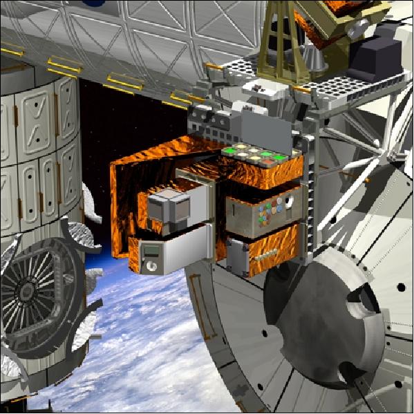
ISS: SOLAR and EuTEF (International Space Station Solar Monitoring Observatory and European Technology Exposure Facility) - External Payloads of the Columbus Laboratory
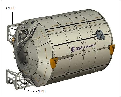
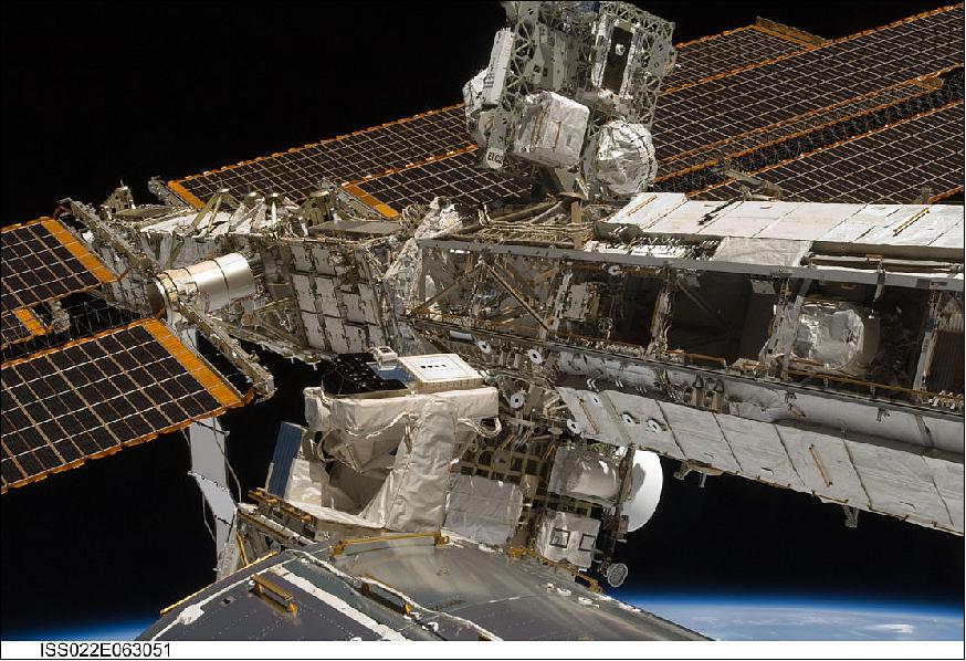
The Columbus External Payload Facility (CEPF) provides four attachment sites for un-pressurized payloads (i.e. platforms to accommodate external payloads). The overall objectives of the external payloads are related to applications in the field of space science, Earth observation, technology demonstrations, and innovative sciences from space. The CEPF consists of two identical L-shaped consoles attached to the starboard cone of the Columbus module in the zenith (top) and nadir (bottom) positions, where each console is supporting two platforms for external payloads or payload facilities. In total, four external payloads (payload facilities) can be operated at the same time.
The attachment sites are: 1 nadir (platform facing earthward), 1 zenith (platform facing upward) and two starboard (platforms face to the right of Columbus as viewed along its line of flight). Each payload may have a mass of up to 290 kg, including the mass of the ExPA (Express Pallet Adapter) and the active FRAM (Flight Releaseable Attachment Mechanism).
• Power capability at each attachment site of up to 1.25 kW is provided by two 120 VDC redundant power feeds of the Columbus Laboratory.
• Data capabilities at each attachment site include a MIL-STD-1553B low rate data line for status data such as caution and warning and failure detection. The attachment sites also provide an Ethernet medium rate data line, for transfer of commanding, ancillary data, and file transfer with rates up to 1.55 Mbit/s. The high data rate line interfaces to the video data processing unit, and transmits up to 32.426 Mbit/s in increments of 32 kbit/s.
The initial set of multi-user payloads on STS-122 are: SOLAR, which is a solar observatory with three scientific instruments, and EuTEF, which is an ensemble of nine individual instruments dedicated to in-orbit technology experiments.
Further (Existing and Planned) Experiments on CEPF
The other two external platform mounting sites (shown at the bottom of Columbus in Figure 1) are reserved for NASA payloads.
In fact, the first multi-user payload, MISSE-6 (Material ISS Experiment-6) exposure facility of NASA, was launched on assembly flight 1J/A (STS-123) of Endeavour, March 11-26, 2008, and attached to the CEPF (Columbus External Payload Facility) during the final EVA by the crew of STS-123 on March 22, 2008. The participating institutions in the MISSE-6 payload are, among others: ASOSR (Air Force Office of Scientific Research), NRL, AFA (Air Force Academy), NASA/LaRC, NASA/GSFC, SNL (Sandia National Laboratory), Utah State University, NASA GRO, The Aerospace Corporation, Boeing Co (prime contractor), etc. - The MISSE-6 payload, consisting of two containers each with hundreds of new materials, will remain attached to the outside of Columbus for about one year before returning to Earth. 1)
More planned European CEPF payloads will succeed the SOLAR and EuTEF payloads. The following payloads are under development as of 2008: ASIM (Atmosphere Space Interaction Monitor) and ACES (Atomic Clock Ensemble in Space).
• The ASIM payload is composed of optical instruments for the observation of high-altitude emissions from the stratosphere and mesosphere related to thunderstorms.
• The core of ACES is a laser cooled Caesium atomic clock known as "Pharao", that will exploit the microgravity conditions onboard the ISS. In addition to the Pharao clock, there are two other elements: a hydrogen maser, and a microwave link (used for time and frequency transfer).
Launch
A launch of the Columbus Laboratory took place on Feb. 7, 2008 on Shuttle assembly flight 1E of Atlantis (STS-122). 2)
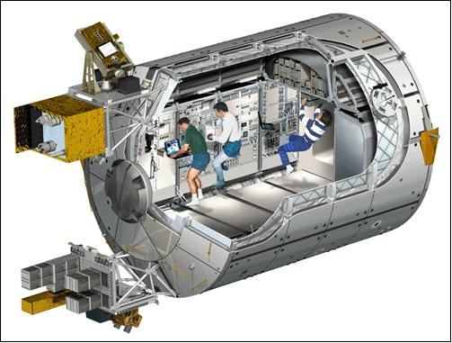
At launch, the laboratory was already outfitted with 2,500 kg of experiment facilities and additional hardware. This includes the ESA-developed experiment facilities such as: Biolab, FSL (Fluid Science Lab), the European Physiology Modules, EDR (European Drawer Rack), and the European Transport Carrier. In addition, two payloads for the Columbus external platforms were carried separately in the cargo bay of the Shuttle: SOLAR (Solar Monitoring Observatory), and EuTEF (European Technology Exposure Facility). 3)
The two external payloads, SOLAR and EuTEF, were installed after the Columbus attachment to the ISS. The SOLAR accommodation is at ExPA-Z (Express Pallet Adapter-Z direction) while the EuTEF accommodation is at ExPA-XO.
Orbit
The International Space Station (ISS) has a nearly circular orbit inclined at 51.63º to the equator with an average altitude that, since assembly began, has ranged between 330 and 400 km.
SOLAR (Solar Monitoring Observatory)
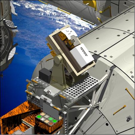
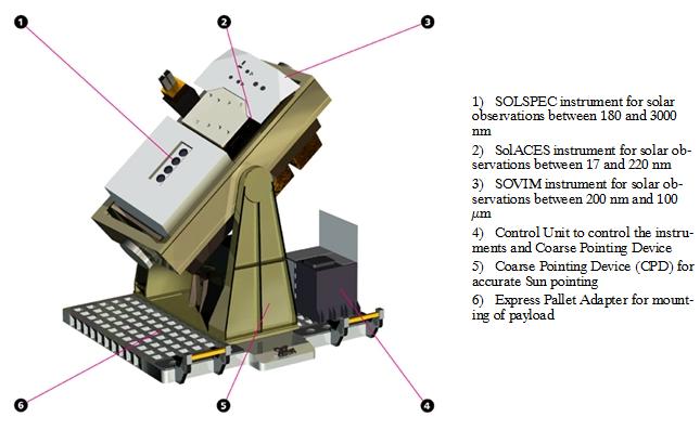
SOLAR is an ESA experiment package consisting of three science instruments, namely SOVIM (Solar Variability and Irradiance Monitor), SOLSPEC (Solar Spectral Irradiance Measurements), and SolACES (Solar Auto-Calibrating EUV/UV Spectrophotometers). In addition, there are the following elements:
• CEPA (Columbus External Payload Adapter)
• CPD (Coarse Pointing Device)
- A two-axes pointing platform that allows instruments direct Sun pointing named CMA (CPD Mechanical Assembly)
- An electronic unit, mainly based on the SPLC (Standard Payload Computer) boards and relevant embedded basic software developed in the frame of the ESA-SPOE program, that provides all SOLAR payload elements with power distribution, TM&C servicing and system management software accommodation named CU (Common Control and Power Distribution Unit)
• Payload system management software
• Electrical harness
• Thermal control hardware.
The overall objective is to measure the solar spectral irradiance with unprecedented accuracy. Knowledge of the "solar constant" and its variations is of great importance for atmospheric modelling, atmospheric chemistry, and climatology applications. The three instruments cover the combined wavelength range from 17-3000 nm in which 99% of the solar energy is radiated. 4)
The SOVIM and SOLSPEC are the upgraded versions of instruments that have already accomplished several orbital flights without failure. SolACES is a new development instrument. The SOLAR package is scheduled to observe the sun for a period of 2 years. 5) 6) 7)
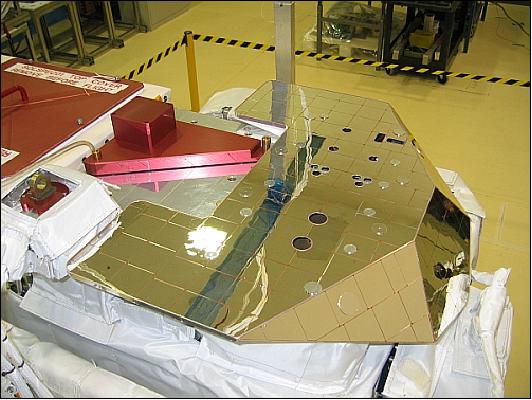
CPD (Coarse Pointing Device). A multi-purpose platform of ESA (developed by Thales Alenia Space-Italia) that has the function of keeping the supported instruments pointed to a target (e.g.: to the sun), compensating for the orbital motion of the ISS. In each orbit, CPD keeps the instruments pointed to the sun during an observation period of about 15 minutes. 8)
CPD provides a movable frame, which can rotate around two axes, thanks to a cardanic type mechanism. The motion is controlled in closed loop, using a sun sensor located on the moving frame, brushless motors and encoders mounted on each axis.
The maximum range of the CPD angular motion is ±25º around the axis compensating for the seasonal variation of the ISS orbit inclination, and ±40º around the axis compensating for the ISS orbital motion. The pointing accuracy is ±1º; the pointing stability is 0.3º over 10 seconds.
The CPD consists of a CU (Control Unit), a CMA (CPD Mechanical Assembly), and a sun sensor. CPD was developed in two versions, one for the SOLAR payload and one for the EXPORT payload. Each version has different instruments accommodation and mass carrying capabilities. For SOLAR the maximum mass carrying capability is 75 kg.
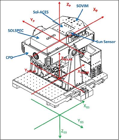
Legend to Figure 5: The SOLAR reference coordinate system is indicated by (XSOLAR; YSOLAR;ZSOLAR), and it is fixed to the static external platform. The reference frame attached to the instruments is indicated with (XP ; YP ;ZP ). The orientation if the ISS attitude reference frame (XISS; YISS;ZISS) is shown for completeness (Ref. 17).
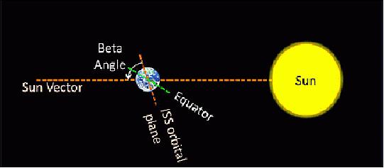
In order to have the instruments pointing at the Sun, the CPD has to compensate for the Sun's apparent motion. The rotation around the XP -axis compensates for the elevation of the Sun over the orbital plane, which varies with the season and with the precession of the ISS orbit. In other words, to correct for the ISS β-angle: the angle between the Sun-Earth vector and its projection on the orbital plane. This rotation is referred to with the indexation angle α. The rotation over the YP -axis, on the other hand, compensates for the Sun's apparent motion along the orbit. This is called the de-rotation angle γ.
The rotation over the YP -axis is limited to ±40º, which results in a maximum observation time of only 20 minutes per ISS orbital revolution. The ISS orbit has an inclination of 51.6º with respect to the Earth equator. This results in a β-angle that varies between ±75.1º over the course of a year. However, the rotation over the XP -axis is limited to ±24º, and as such the Sun observation is only possible at specific periods of the year. A period of consecutive days of the Sun pointing opportunities is referred to as Sun Observation Window (SVW). The concept of SVW is illustrated in Figure 6, which shows the evolution of the ISS β-angle over the year 2012. The SVWs are numbered incremental, where SVW#1 is defined as the first observation period after the commissioning phase.
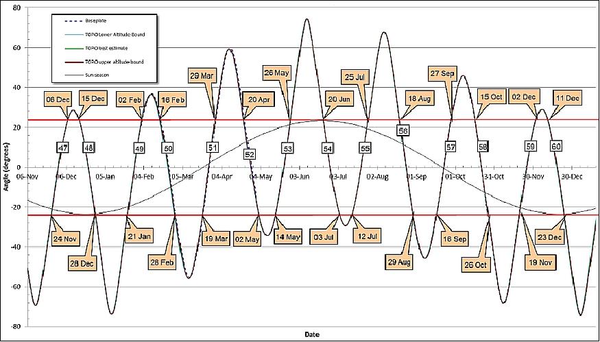
Legend to Figure 6: Sun observation by the SOLAR instruments is only possible when the ISS β-angle is in the range ±24º, resulting in the so-called SVWs (Sun Visibility Windows). Start and end dates of the SVW are indicated, as well as the SVW number. The value for the ISS β-angle is retrieved from various NASA sources.
Note: One important parameter which describes the attitude of the Station with respect to the sun is the β-angle (beta angle). This is the angle between the Sun vector, which is the vector between the earth and the sun and the ISS orbital plane. In Figure 1. the ISS beta angle and its variation during a one year period are represented.
Status of SOLAR
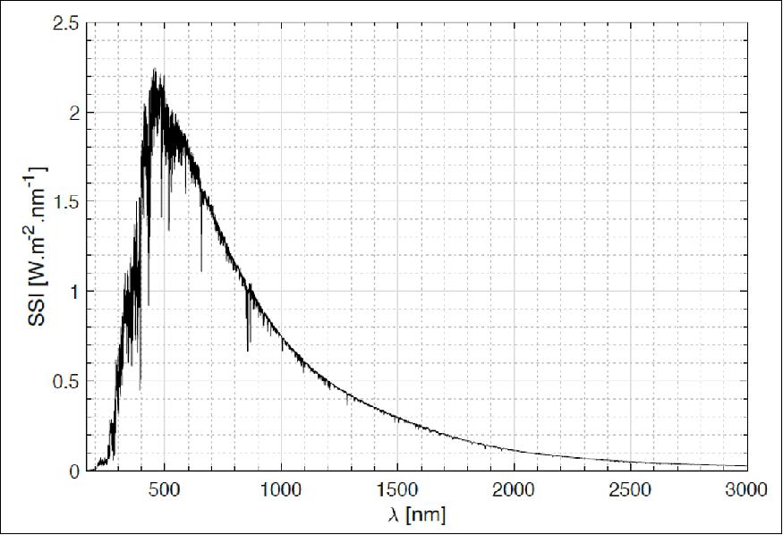
• December 19, 2017: For almost a decade, the International Space Station tracked the Sun to measure our star's energy. Now, years of work have delivered the most accurate-ever data on the Sun's power – but the journey to achieve this feat was almost abandoned before the experiment ended. 9)
- Computer models can calculate and predict large-scale events such as our planet's weather and climate but they need hard numbers to work on. Processing power can simulate our planet, but the researchers need the numbers to key into the computer models and, with so many numbers flowing, inaccuracies quickly add up.
- This is where the SOLSPEC instrument comes in. Part of the Solar package on the International Space Station, it was launched with the European Columbus space laboratory in 2008 and tracked the Sun until it was shut down this year. It measured the energy of each wavelength in absolute terms and its variability – a feat that requires a higher order of precision than relative measurements. As an analogy, it is easy to feel a change in temperature, but nobody on Earth can sense the exact temperature without a thermometer.
Legend to Figure 9: For almost a decade, Solar tracked the Sun to measure our star's energy. The teams behind the facility, the Belgian BIRA-IASB institute and France's Latmos, improved the accuracy of the reference data across the Sun's spectrum down to 1.26% and, more importantly, an estimation of how accurate this variation is – meaning the team not only knows how much energy/m2 emitted per wavelength, but also the margin of error. This number might seem insignificant, but the more accurate it is, the better researchers can understand how our climate has changed and is changing.
- Painstaking measurements: The Solar facility achieved these measurements by repeatedly rotating to point at the Sun as the Space Station flew around Earth every 90 minutes. As it measured each wavelength in the Sun's spectrum, the rays had to be separated into separate wavelengths. Gratings with extremely small nm-sized grooves – up to 3600 per mm – spread sunlight like a prism on to receivers.
- On Earth these measurements are made in a laboratory with a constant temperature to avoid any disturbances and ensure accurate measurements. The Space Station offered far from ideal conditions, aside from the general vibrations that come with an orbital outpost, the Station passes from light to darkness and back again every 45 minutes – almost 12,000 times in the instrument's lifetime. Each pass caused the temperature to fluctuate by 30°C – straining the instruments as well as expanding and contracting the instrument's components resulting in skewed measurements.
- Of course, these conditions were well known before the instrument was built and launched, so engineers designed Solar and SOLSPEC to cope with the harsh climate outside the Space Station. Despite this, initial readings when it was turned on in 2008 were not as accurate as expected.
- The teams despaired, but did not give up as they realized they could analyze the data at a higher level to understand the readings over time. Towards the end of its mission, SOLSPEC was stressed to its limits to test how it was affected by external thermal factors and to calibrate the machine better. The operators left Solar working throughout the night and even moved the whole Space Station to keep it pointing at the Sun for as long as possible.
- "Metrology is the science of measurement and it requires painstaking work to achieve the hair-splitting accuracy we now have for the Sun's output," says ESA's Astrid Orr, ESA's project scientist for Solar. "The team put the instrument and themselves through extremes to understand and calibrate the readings, spending years meticulously going over the numbers. One of the original scientific goals set in 1996 for Solar was to obtain the most precise possible absolute measurement of the solar irradiance: objective achieved."
- With the Solar facility now powered off, researchers still have over nine years of data to analyze and interpret the variability in the Sun's spectrum. Results are still coming in. The quest for more accuracy continues next year with NASA's TSIS-1 on the Space Station.
• On February 15, 2017, ground control in Belgium switched off a package that had been continuously watching the Sun from the International Space Station for nine years. ‘SOLAR' has been measuring most of the radiation emitted by our closest star across the electromagnetic spectrum. Built to run for only 18 months, it was still working until today – exceeding all expectations. SOLAR's observations are improving our understanding of the Sun and allowing scientists to create accurate computer models and predict its behavior. 12) 13)
- To predict how the Sun behaves, scientists create complex computer models to build a virtual star. With more observations, scientists can fine-tune their models. Modelling and predicting the Sun's activity with precision is an important step towards understanding humankind's effect on Earth's climate.
- Between 2012 and 2016, the Space Station turned itself five times to position SOLAR so that it could track the Sun without interruption for a complete solar day – around a month of Earth days. It was the first time the Station changed attitude for scientific reasons alone and a huge achievement – it's not every day that you move a 450 ton orbital outpost.
- Today, SOLAR was moved to a parked position where it was secured with a pin. Even during its last days, SOLAR was delivering important data.
- The teams at the control center in Brussels, Belgium, used the final moments to stress the hardware to its limits and gain a better understanding of how the observations have been affected by age and the intense changes in temperature it endures outside the Station. Using this extra information, researchers are developing software that will improve calibration of parts of the data.
- ESA's project leader, Astrid Orr, comments, "After all these years of gaining valuable information about our Sun it is an emotional moment for the team, but SOLAR has far exceeded everyone's expectations. - This kind of research does not deliver pretty pictures, but numbers. I tip my hat to the researchers who patiently sort through the wealth of data – this field of science may seem tedious and unexciting to the outside world, but climate studies heavily rely on these data to understand the world we live in and how we are shaping it."
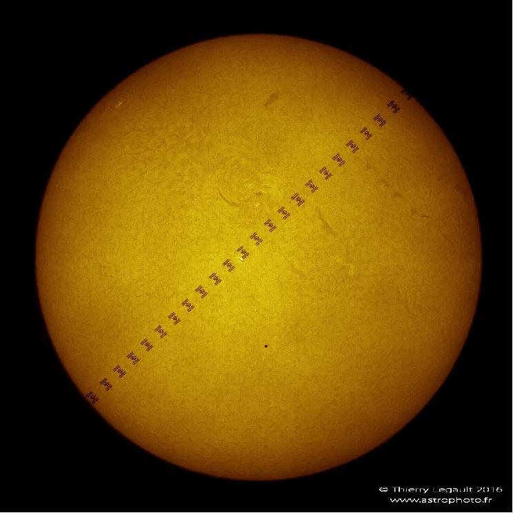
• On May 9, 2016, Mercury passed in front of the Sun as seen from Earth. These transits of Mercury occur only around 13 times every century, so astronomers all over Earth were eager to capture the event. For astrophotographer Thierry Legault, capturing Mercury and the Sun alone was not enough, however – he wanted the International Space Station in the frame as well. 14)
- To catch the Station passing across the Sun, you need to set up your equipment within a ground track less than 3 km wide. For Thierry, this meant flying to the USA from his home near Paris, France.
- On 9 May, there were three possible areas to capture the Station and Mercury at the same time against the solar disk: Quebec, Canada, the Great Lakes and Florida, USA.
- Choosing the right spot took considerable effort, says Thierry: "Canada had bad weather predicted and around Florida I couldn't find a suitably quiet but public place, so I went to the suburbs of Philadelphia."
- With 45 kg of equipment, Thierry flew to New York and drove two hours to Philadelphia to scout the best spot. Even then, all the preparations and intercontinental travel could have been for nothing because the Station crosses the Sun in less than a second and any clouds could have ruined the shot.
- "I was very lucky: 10 minutes after I took the photos, clouds covered the sky," says a relieved Thierry. "Adrenaline flows in the moments before the Station flies by – it is a one-shot chance. I cannot ask the space agencies to turn around so I can try again. Anything can happen."
- The hard work and luck paid off. The image of Figure 12 includes frames superimposed on each other to show the Station's path. Mercury appears as a black dot at bottom-center of the Sun.
- For Thierry, the preparation and the hunt for the perfect shot is the best part. "Astrophotography is my hobby that I spend many hours on, but even without a camera I encourage everybody to look up at the night sky. The International Space Station can be seen quite often and there are many more things to see. It is just a case of looking up at the right time."
• May 2014: Although the SOLAR mission was initially granted for a duration of 1.5 years, a mission extension up to 2017 was recently approved. This means that the SOLAR mission is covering the end of solar cycle 23, including the deep minimum in 2009, and almost completely solar cycle 24. The data gathered by the three instruments are providing accurate measurements of the SSI (Spectral Solar Irradiance) and its variability as a function of solar activity. 15)
The SOLAR bridging was not immediately realized: two and a half years have passed from the idea to the implementation of the first bridging campaign. Intense pre-coordination took place between the different international partners (IPs) and the strong support from ESA was crucial at all times. Once ESA was convinced of the additional scientific value of the SOLAR bridging, the request process could be initiated.
The concept of SVW (Sun Visibility Window) is illustrated in Figure 6, which shows the evolution of the ISS β-angle over the year 2012. The SVWs are numbered incremental, where SVW#1 is defined as the first observation period after the payload's commissioning phase.
- Bridging No 1: SVW #59-60 lasted from 19 November, to 23 December, 2012, yielding a total observation period of 35 days (Ref. 15).
- Bridging No 2: SVW#66-67 started 18 June, 2013, and lasted until 24 July, 2013.
- Bridging No 3: SVW#71-72. The third bridging campaign merged SVW#71 and SVW#72, making SOLAR observations possible from 16 November until 22 December, 2013.
- A request has been made in the mean time to repeat the bridging experiment a fourth time during the summer solstice in 2014. The success of this event is attributable to the thorough support from ESA and the NASA counterparts, and the commitment of the science teams.
• SOLAR is operating nominally in 2013. - Following completion of the latest Sun Visibility Window (67th) on July 24, the Solar facility has been in a standby mode while awaiting the next Sun Visibility Window. Sun Visibility Windows for the Solar facility, located on the external surface of Columbus, are open for the facility to acquire scientific data when the ISS is in the correct orbital profile with relation to the Sun. During this two week period until August 9 , the SolACES instrument from SOLAR has been in a warm-up configuration (as a work-around to protect the instrument's optics from degradation). 16)
- The SOLAR payload facility has been studying the Sun's irradiation with unprecedented accuracy across most of its spectral range for more than 5 years. This has so far produced excellent scientific data during a series of Sun observation cycles. An extension to the payload's time in orbit could see its research activities extend up to early 2017 to monitor the whole solar cycle with unprecedented accuracy (Ref. 16).
• On 30 November, 2012, at GMT18:30 the International Space Station started an attitude change maneuver. Thanks to this small change in pitch, roll, and mainly yaw (about 7.5º) the SOLAR (Solar Monitoring Observatory) instrumentation could perform measurements of the spectral and TSI (Total Solar Irradiance) uninterruptedly over a period of 35 days. This event is historical as it was the first time ever the ISS rotated solely for a scientific experiment. Without this small change in attitude, the maximum SOLAR observation period would not exceed 14 days due to the mechanical constraints (aspect angle to the sun) of the platform. An entire rotation of the Sun was monitored quasi-continuously for the first time in history from the ISS and close daily collaboration was demonstrated between different IPs (International Partners) for a common science goal. 17)
Having quasi-continuous and long-term SOLAR observations is vital for a better understanding of the solar UV/EUV variability and will: provide data to investigate the impact of the solar variability on the Earth's climate; contribute to the understanding of the complex processes taking place in atmospheric physics; improve the modelling of the solar EUV/UV irradiance and its relation to solar active regions and flares, the solar-terrestrial connection, and certain aspects of the space weather. Therefore, it is important to repeat these bridging campaigns as much as possible, with an opportunity every solstice. The success of this event is attributable to the thorough support from ESA and the NASA counterparts, and the commitment of the science teams.
Changing the ISS Attitude to Maximize the Science Return of the SOLAR Payload (Ref. 17)
The two remaining operational instruments, SOLSPEC and SolACES,on-board the payload, are designed to measure the solar irradiance in the wavelength range 16 to 3000 nm.
However, due to the SOLAR instruments' unique location and because of the mechanical constraints of the platform, observations are only possible at most two weeks a month, for not longer than 20 minutes per ISS orbital revolution. However, since the SOLAR mission will be operational for an almost complete solar cycle, it will provide data on the long-term evolution of the spectral solar irradiance, important for, among others, atmospheric science.
In order to study the short-term variability, it is important to have measurements covering a complete solar rotation. During the winter and summer solstices the time between two consecutive observation windows is the shortest. By changing the ISS attitude by only a few degrees from its standard "Torque Equilibrium Attitude", this gap in the observations can be bridged.
Between November 30 and December 12, 2012, the ISS roll, and mainly yaw (about 7.5º) were modified, allowing the SOLAR instruments to monitor the Sun for more than 35 days in a row, covering a complete solar rotation. This event is historical as it was the first time ever the ISS rotated exclusively for a scientific experiment. The change of the ISS attitude was reached by solely using the CMGs (Control Momentum Gyroscopes). This small attitude change and did not negatively affect any of the other external payloads and the minimal effort resulted in a great scientific benefit.
During this extended observation period, data of the solar spectrum were intensively collected. A more complete dataset of the solar irradiance will contribute to a better understanding of the effect of the solar variability on the Earth's atmosphere.
• A new Sun visibility window (the 50th) for the SOLAR facility to acquire scientific data had started on February 15, 2012. Sun visibility windows for SOLAR are open for the facility to acquire scientific data when the ISS is in the correct orbital profile with relation to the Sun. 18)
• On June 27, 2011, another of the periodic sun visibility windows opened for the SOLAR facility to acquire scientific data. Sun visibility windows are open when the ISS is in the correct orbital profile in relation to the sun. So far, the two SOLAR payloads have been studying the sun's irradiation on orbit with unprecedented accuracy across most of its spectral range for more than three years. This has produced excellent scientific data during a series of Sun observation cycles. Following conclusion of the detailed technical feasibility study for on-orbit lifetime extension, the science team will be able to continue gathering further science data in a period of increasing solar activity up to 2013 and possibly beyond. 19)
• The SOLAR payloads (SOLSPEC and SolACES) are operating nominally in 2010 providing highly valuable and very accurate science data during every sun observation period, i.e. whenever the orientation of ISS with respect to the sun is compatible with the mechanical capabilities of the SOLAR platform. - This has led to the decision to extend the time of SOLAR in orbit by several years, to the end of 2013 and possibly beyond in order to catch the progressive increase of 11-year sun activity cycle. 20)
SOLAR studies the sun with unprecedented accuracy across most of its spectral range, especially the UV light normally absorbed by the Earth atmosphere. SOLAR allows measuring periods of at least 15 minutes per orbit totalling approximately 600 hours per year of solar observation.
• In the fall of 2009, ESA decided to extend the SOLAR mission for several years (from 1.5 to 3 years). Since the Columbus deployment, this Sun tracking platform provides excellent scientific results. 21)
• In late October 2008, the SOVIM instrument suffered an unrecoverable failure (power unit breakdown).
• After a few weeks of operation, it became clear that the operational constraints followed by the CCC and based on the operations of Columbus as a system were limiting the SOLAR operations in ensuring sustainable support to this scientific mission. In view of real-time issues, some adjustments to the operational concepts were made in concert with the Columbus Flight Control Team, ESA and the Pis (principal investigator) to ensure the most effective support for the mission. 22)
• On April 30, 2008 - solar measurements started with SOVIM and SOLSPEC instruments with regular acquisition of spectra and calibration runs. During this sun observation period, the SOLAR platform, SOVIM and SOLSPEC sun sensor positions have been correlated during a so-called 'criss-cross' procedure maneuver.
• Initial sun tracking was started on April 29, 2008, but the sun was not in the proper β-angle range to allow for nominal data acquisition, i.e. SOLAR platform went into stand-by mode when trying to track the sun.
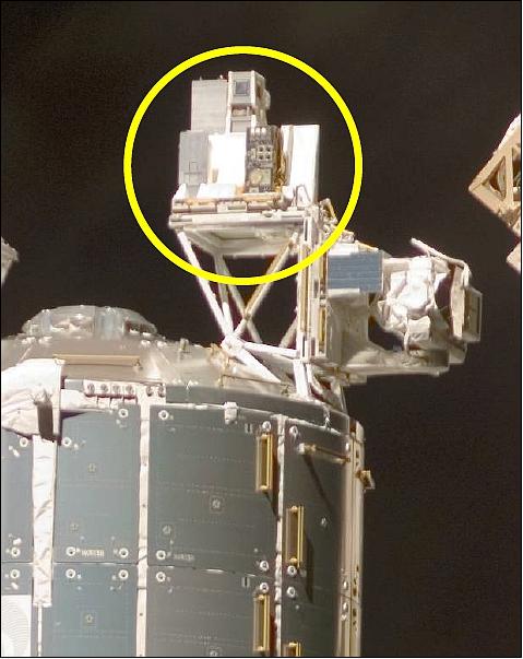
• The SOLAR payload package was installed on the Columbus External Payload Facility (CEPF) during the Shuttle (STS-122) mission in February 2008. After that, the SOLAR payload package was controlled from ground, via the CCC (Columbus Control Center) in Oberpfaffenhofen, Germany, and the User Support and Operations Centers (USOCs) involved. The SOLAR instruments are operated by the Belgian User Support and Operations Centre (B.USOC) since then.
SOVIM (Solar Variability and Irradiance Monitor)
SOVIM is an ESA instrument, designed and developed at PMOD/WRC Physikalisch-Meteorologisches Observatorium Davos, World Radiation Center, Switzerland (PI: C. Fröhlich), in cooperation with investigators from Belgium, France, ESTEC, Switzerland, and USA. The overall objective is to measure TSI (Total Solar Irradiation) and SSI (Spectral Solar Irradiance). SOVIM is of SOVA heritage flown on EURECA-1 (launched July 31, 1992 and retrieved July 1, 1993).
The objective of SOVIM is to monitor the sun's irradiance with high precision, stability and accuracy; the pointing accuracy is of the order of 1º to compensate for ISS motions. SOVIM observations are conducted during the sun-pointed periods of 10-15 minutes per orbit throughout the mission. TSI measurements are performed with active cavity radiometers (PMO6 and DIARAD) which are traceable to the SI scale of irradiance through direct comparison with cryogenic radiometers on the ground and in vacuum for the PMO6, and thorough characterization in the laboratory for the DIARAD. SSI measurements are carried out by SPM (Sunphotometers) of the type now operating successfully in VIRGO/SOHO. A detector based calibration method, directly traceable to the scale established by cryogenic radiometers, is used to calibrate the SPM with high accuracy. Specific TSI and SSI objectives are: 23) 24)
• To obtain quasi-continuous high quality measurements of the solar irradiance variation
• To determine with high accuracy the amount of spectral redistribution of the solar output
• To search for the long periodicities or quasi-periodicities found in other solar parameters
• To study the influence of active regions and other large scale solar structures on the solar irradiance
• To investigate the energy storage in the convection zone in connection with the energy blocking of active regions
• To investigate the mechanisms of solar radiative forcing of climate change on seasonal to decadal time scales
• To continue the historical TSI monitoring record by linking the present SOLSTICE (UARS), VIRGO (SOHO), CERES (Terra), ACRIM-III (ACRIMSAT), and future CERES (Aqua), TIM, SOLSTICE (SORCE), TIM (NPP, NPOESS), and SOVAP (Picard) measurements.
The SOVIM instrument consists of three packages: SOVIM1, SOVIM2 and SOVIM3.
• SOVIM1, developed at IRMB, contains one absolute radiometer DIARAD (Dual Irradiance Absolute Radiometer). DIRAD is composed of two cylindrical cavities coated inside with diffuse black and mounted next to each other on the same heat sink. The flat bottom of the cavities are in fact heat flux transducers on which heating elements have been mounted. Both cavities see the same thermal environment through accurately know circular apertures. The operation is based on electrical substitution. The difference of the electrical power fed to the active channel when its shutter is open (exposed to the sun) and when it is closed is proportional to the incident solar irradiance. The SOVIM1 mass is 7.3 kg, power = 11.5 W.
• SOVIM2, developed at PMOD/WRC (Switzerland), contains two absolute radiometers, an IR Radiometer, four SPM with three independent channels each (type1: 402, 500 and 865 nm, type2: 310, 610 and 719 nm, all redundant) and a two axis pointing monitor (TASS). The SOVIM2 mass is 13.3 kg, power = 18.5W.
• SOVIM3, developed at PMOD, contains the microcomputer (80C86) based experiment controller, part of the data acquisition system and the power and data interfaces to ISS. The SOVIM3 mass is 3.4 kg, power = 3.5 W.
Data acquisition is performed by parallel VFCs (Voltage Frequency Converters) with a frequency of about 500 kHz. The basic sampling period is 10 s. Electrical calibrations are performed at zero, half scale and full scale. The pointing provided by CDP is ±1º (2 sigma) with a stability of 0.3º over 10 s. ISS position and attitude data are available for post-factum data analysis. SOVIM data are processed at SROC (Space Remote Operation Center) located at ESA.
SOLSPEC (Solar Spectral Irradiance Measurements)
SOLSPEC is an ESA instrument [PI: G. Thuillier of CNRS/SA (Service d'Aéronomie), Verrieres le Buisson, France, with cooperation of IASB (Institut d'Aéronomie Spatiale de Belgique), Belgium, LSW (Landessternwarte) Heidelberg, Germany, Switzerland, UK, and USA]. SOLSPEC is of Spacelab-1 (Nov. 28 to Dec. 8, 1983), ATLAS-1 (1992), ATLAS-2 (April 1993), EURECA (1992-1993), and ATLAS-3 (Nov. 1994) heritage (Spacelab and ATLAS were Shuttle missions).
The objective of SOLSPEC on Columbus is the measurement of the solar irradiance in the spectral range from 165-3100 nm using three double spectrometers and an on-board calibration device. The following science goals are being pursued with the instrument: 25)
• Achievement of absolute measurement (with uncertainties of 1.25% in UV and 1% in the visible and IR ranges)
• Study of solar variability over both short and long time scales beginning os solar cycle 24.
• Correlative studies between the spectral and the total solar irradiance, utilizing other instruments on SOLAR (SOVIM and SolACES) and the atmospheric and climatological implications of their variability.
SOLSPEC is comprised of three spectrometers which cover the ultraviolet (from 165 to 370 nm), visible (from 350 to 900 nm) the and infra-red (from 800 to 3080 nm) as well as a calibration system. The spectrometers use holographic networks whose precision is of 0.01 nm. The calibration system comprises two lamps with deuterium, two lamps with tungsten, and a cathode one. The instrument is gaged with a blackbody to 3300 K and a set of tungsten lamps.
Item | SOLSPEC-ATLAS | SOLSPEC-SOLAR |
Spectrometer | 3 | 3 |
Spectral range (nm) | 210-2400 | 165-3080 |
UV spectral range / bandwidth | 210-370/1.2/0.4 | 165-370/1.2 |
Visible spectral range / bandwidth | 350-880/1.4/1. | 285-910/1.6 |
IR spectral range / bandwidth | 800-2400/20./4. | 650-3080/8. |
D2 lamps | 2 from Hanau | 2 from Cathodeon (SUSIM) |
Tungsten ribbon lamps | 2 from Hanau | 4 from Jelosil (WINDII) |
Hollow cathode lamp gas | He | Ar |
Sun position sensor | no | yes |
Protective quartz plates | no | 2 per spectrometer |
BB calibration | LSW | PTB |
D2 and FEL calibration lamps | NIST | PTB and NIST |
IR detection | 2 gains | 3 gains |
Electronics and software | - | Fully redesigned |
Mass (kg) | 32 | 27 |
Time to record a full spectrum | 11 minutes | 11 minutes |
Accuracy | 3% | 1-2% |
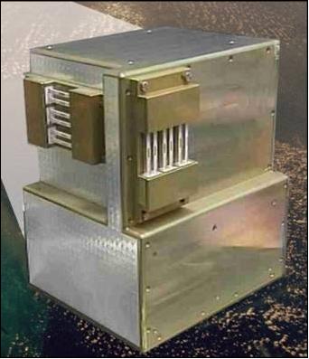
SolACES (SOLAR Auto-Calibrating EUV/UV Spectrophotometers)
SolACES is a DLR and ESA funded instrument (PI: G. Schmidtke of the Fraunhofer IPM (Institut für Physikalische Messtechnik), Freiburg, Germany, with co-investigators from Germany and USA). SolACES is a new instrument covering the solar irradiance in the EUV/UV spectral range of 17-220 nm. The primary science goal of SolACES is to observe the absolute (spectral) irradiance (the solar "constant" in physical units) of the full disk of the sun in the EUV/UV range and its variation with time. The spectral resolution of these measurements varies between 0.5 and 2 nm depending on the wavelength in the spectrum. 26) 27)
A novel feature of SolACES, improving all similar space experiments from the past, is its capability to auto-calibrate the instrument repeatedly during the whole mission at a minimum rate of twice a month. This accounts for the inevitable efficiency changes of the instrument, and allows EUV flux measurements with an up to now unprecedented absolute radiometric accuracy of better than 10%. So far, EUV flux measurement uncertainties were typically on the order of 20 to 400% or more.
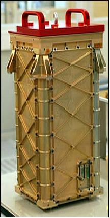
Instrument mass, size | 23 kg, 25 cm x 29 cm x 60 cm |
Electrical power consumption | < 25 W (average), 60 W (max) |
Data rate | ~ 1 kbit/s |
Spectral range | 17 - 220 nm (EUV/UV) |
Spectral resolution | 0.5 - 2 nm |
Radiometric accuracy | < 3% |
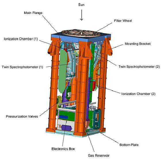
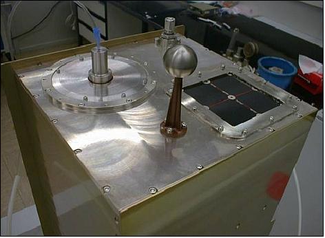
SolACES Gas Reservoirs
- Measures solar irradiance through various filters with a photodetector
- One filtering method by observing solar irradiance through ionized gas
- Gas supplied from four tube-shaped gas reservoirs
- Three types of gases: Xenon, Neon, and Nitric Oxide diluted with Xenon.
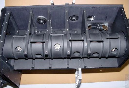
Major elements of the instrument are: filter wheel, stepper motor, spectrometers, ionization chamber, gas supply, electronics unit (control, data acquisition, communication). Solar irradiance measurements (full disk) are obtained with four grating spectrometers.
To obtain high radiometric accuracy of better than 10%, a double ionization chamber is assigned to each of the spectrometers as primary detection standard. Optical bandpass filters are mounted on a filter wheel and placed at the entrance apertures of the spectrometers and ionization chambers, they establish the radiometric link between the devices (instrument calibration uses the optical bandpass filters in conjunction with the double ionization chambers as radiometric standards). The grating spectrometers are designed as scanning monochromators operating at fixed incidence angles. The deflected radiation is monitored by rotating an assembly containing a parabolic mirror, an exit slit and a CEM (Channel Electron Multiplier). The dispersed radiation is focused through the spectrometer exit slit by a parabolic mirror and collected by CEM operated in a pulse counting mode. The optical length of the ionization chamber of 0.5 m is divided into two identical electrode sections. In addition, the transmitted radiation is measured by a silicon diode detector located at the end of the absorption path. The data permits the absolute quantification of the solar flux in the prescribed spectral range.
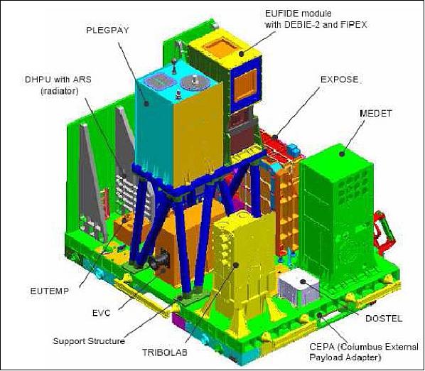
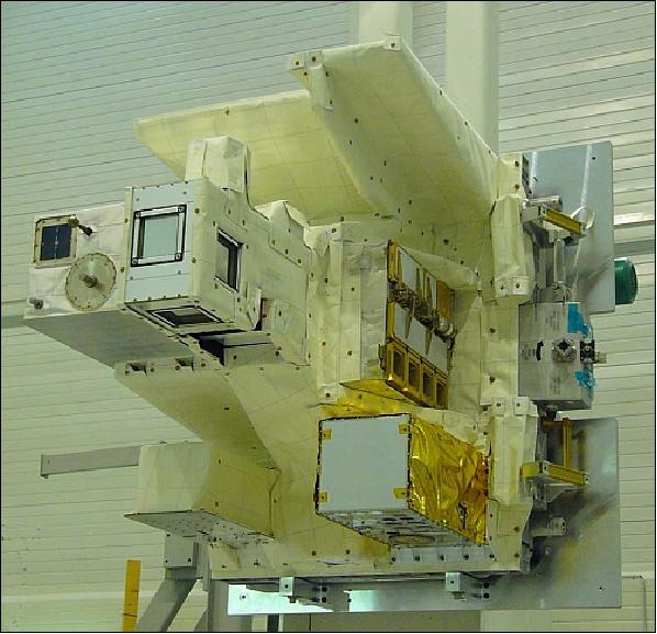
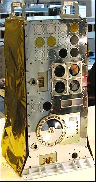
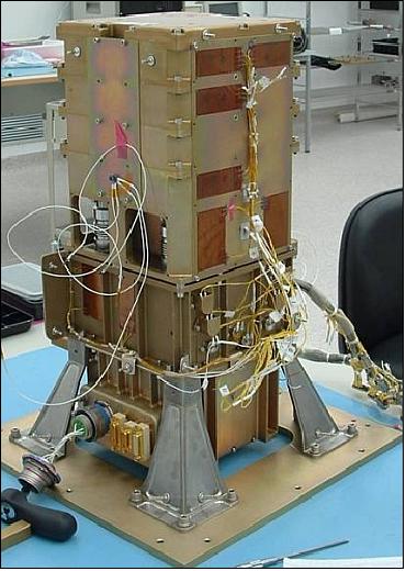
EuTEF (European Technology Exposure Facility)
EuTEF is a fully automated, multi-user payload facility mounted on the outside of the Columbus laboratory carrying a suite of experiments that require exposure to the open space environment. The experiments cover a variety of disciplines including material science, physics, astrobiology and astronomy. 28)
EuTEF is attached to one of the four CEPF (Columbus External Payload Facility) locations, namely ExPA-XO (Express Pallet Adapter), available for scientific payloads. The entire EuTEF instrument suite is installed onto ExPA, which provides common mechanical/thermal/electrical/command and data interfaces and ensures interfaces to CEPF. In addition, data interfaces to the Orbiter are provided. The main data lines provided by the CEPF Data Management System (DMS) are the MIL-STD-1553B data bus and a redundant Ethernet.
The ISS Ground Segment provides EuTEF with the following major services in a transparent way:
• delivers EuTEF downlinked TM Data to EuTEF Ground Segment
• receives from EuTEF Ground Segment requests of Telecommands issue and files transfers to its Flight Segment and takes care to uplink the requested data to ISS Flight Segment for eventual delivery to EuTEF.
In total, the EuTEF payload mass is under 350 kg and requires less than 450 W of power. EuTEF is specifically designed to facilitate the rapid turnaround of experiments and for its first configuration on orbit will accommodate nine different instruments.
Status of EuTEF
• After a successful mission of 1.5 years in open space, the EuTEF platform has been returned to Earth with the Shuttle 17A (STS-128) mission on Sept. 11, 2009.
• Since the beginning of the mission in February 2008, all the instruments have been extensively used and have generated science and technology data. However, during the EuTEF mission, most of the platform had to be put operationally on-hold, due to a safety hazard identified late for the PLEGPAY instrument. - After several months of partial activities, EuTEF was granted a resumption of its in-flight activities, up to the successful return of the whole EuTEF platform in September 2009 (Ref. 21).
For the active experiments, data collection has been pursued to the maximum extent and the platform was continuously monitored for 18 months on a 24/7 basis. For the passive experiments, data analysis could only start after the samples had been returned to Earth and distributed to the respective laboratories.
• The EuTEF payload package was installed on the Columbus External Payload Facility (CEPF) during the Shuttle (STS-122) mission in February 2008. After that, the EuTEF payload package was controlled from the ground, through the CCC (Columbus Control Centre) in Oberpfaffenhofen, Germany, and the User Support and Operations Centers (USOCs) involved.
EuTEF Instrument Suite
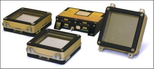
DEBIE-2 (DEBris In Orbit Evaluator)
DEBIE-2 is a standard in-situ space debris and micrometeoroid monitoring instrument. DEBIE-2 is basically identical to DEBIE-1 flown onboard the PROBA satellite of ESA (launch of PROBA on Oct. 22, 2001). DEBIE-2 consists of mechanically four separate subunits: three Sensor Units (SU) and a Data Processing Unit (DPU). The detecting area is 3 x 100 cm2. 29)
The DEBIE instrument is based on a prototype sensor unit developed by UniSpace Kent (USK) at Canterbury, England. The idea is to combine several different detectors to improve the reliability of the measurement. Patria Finavitec has been the prime contractor for ESA and designed the electronics in developing an industrial version of the instrument. Subcontractors include Metorex International and Space Systems Finland. UniSpace Kent has provided scientific support.
The prime objective of DEBIE-2 is to measure mass and velocity of sub-mm sized particles. Each SU implements a basic impact detector measuring the plasma generated by the impacts, the momentum and penetration of a thin aluminum foil. The detection area of the SU is 10 cm x 10 cm.
The SU provides proximity electronics for three plasma detector channels, two piezoelectric transducers (PZT) and two temperature sensors. The charge collection wires of the plasma channels are biased to ±50 V. The analog chains of the plasma and PZT channels are in principal similar to each other. A high gain charge amplifier is used to provide most of the sensitivity. It is followed by a filtering/low gain stage. The main difference between the channels is the band width characteristics, which is optimized for each channel. Finally the amplified and filtered signal is sampled by a peak detector.
Two plasma detectors are placed in front of a thin aluminum foil, one for electrons and one for positive ions. They measure the plasma generated by the particle impacts on the foil. Two piezoelectric transducers are coupled mechanically to the foil and measure the momentum of the impact. Particles with sufficient energy to penetrate the foil are detected by the plasma detector (electrons) placed behind the foil. The particle velocity and mass can be calculated from the measured parameters with the aid of predefined calibration data. The instrument can detect particles with a mass of 10-15 g or larger (depending on the impact velocity).
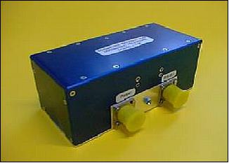
DOSTEL (DOSimetric Radiation TELescope)
DOSTEL is a small radiation telescope (sponsored by ESA, developed at the University of Kiel and DLR, Germany) with the objective to measure time dependent fluence rates of charged particles and their corresponding dose rates and LET (Linear Energy Transfer) spectra. The experiment uses two sensor types: PIPS (Planar Silicon Detectors) and PIN diodes. The specific goal is to gather scientific data on the radiation environment outside the ISS (measurement of radiation doses that astronauts experience during EVA activities). DOSTEL continuously monitors temporal variation of the charged particle count rate, the dose rate, and the LET spectra. Two modes of operation are being performed: 30)
• Single detector mode for dose, fluence and LET measurements
• The single event mode provides energy deposit and time records of each individual particle in all five detectors.
Heritage: DOSTEL measurements were previously obtained on the Mir station (in various locations during the period Oct. 1997 - Jan. 1998), as well as inside the Shuttle on flights STS-76, -81, and -84 which were flown to the Mir station. DOSTEL measured also the environment radiation inside the US Lab of the ISS in the timeframe March to August 2001. 31) 32)
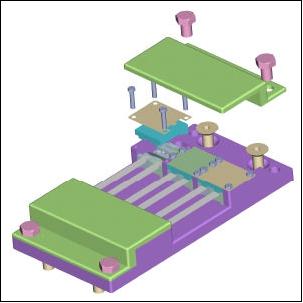
Instrument
The detector unit uses five silicon sensors for measurements. The detector telescope head is built up by two PIPS detectors and one PIN diode. The other two PIN diodes are fixed to the one print board and mounted towards the other two directions.
Each detector is connected to an independent analog signal section consisting of a charge sensitive amplifier (CSA) with 2pF integrating capacitor followed by a two-step pulse amplifier (PA1, PA2) and two peak detectors. For noise reduction purpose, two RC-filters with equal individual time constants of 1 µs are included in each detector signal line. Together with a multiplexed 8-bit ADC this design allows a pulse height analysis of the detector signals with different resolution for the low and high energy deposit region. The power requirement is ±5 Volt for the CSAs and 70 Volt detector bias voltage (high impedance, less than 1 µA per detector). The selection of the sensor is controlled by the software and the power and data lines are switched via a multiplexer on the main board.
The main component of the digital section is the HC711 8-bit microcontroller. This circuit controls detector unit selection, data sampling, preliminary analysis and data reduction, internal intermediate storage and data transfer to the external main storage. The internal clock will be synchronized to mission elapsed time in order to correlate the measurement to orbit positions.
Data products are time dependent fluence rates of charged particles and their corresponding dose rates.
EuTEMP (EuTEF Thermometer)
EuTEMP is a multi-input temperature recording unit (regarded as support equipment for other instruments). Is is being used to acquire temperatures across the EuTEF facility after ascent and during the stay of EuTEF on ISS. EuTemp is an autonomous and battery self-powered temperature acquisition unit able to survive in extreme temperatures for several days after launch.
The role of EuTEMP is required in particular during the installation of EuTEF on the Columbus module. At that stage a critical phase will occur, called the transference phase, where heaters are switched off and the thermal control can only be achieved by passive means. During this phase, whose duration depends of the complexity of the units to install, the temperature can drop to very low values. The space environment is very aggressive due to the absence of an atmosphere and to the levels of solar radiation. Temperatures can vary very rather quickly from extremely cold (-140ºC) when the equipments are in shadow, to very hot (+400ºC) when exposed to the sun. 33)
EuTEMP was developed by the EFACEC Group of Portugal. The EuTEMP data are being transmitted (MIL-STD-1553B) via Columbus and ISS to the ground.
EVC (Earth Viewing Camera)
EVC) is a fixed-pointed Earth-observing camera, located on EuTEF. The main goal of the system is to capture color images of the Earth's surface, to be used as a communication tool to increase the awareness of the general public on the ISS and as a promotional tool to demonstrate the use of the ISS for observation purposes to the potential user community.
EVC is a digital camera proposed and provided by Carlo Gavazzi Space of Milan, Italy. An agreement between ESA and Carlo Gavazzi Space was signed in March 2004 whereby each partner would provide half of the required funding for the development of the camera. 34)
The EVC points continuously at a fixed angle toward the Earth. The camera weighs 7.8 kg and measures 0.4 m x 0.28 m x 0.16 m. It uses a commercial, off the shelf, sensor provided by Kodak, with a 2 k x 2 k detector. EVC is able to capture color images of the Earth's surface that cover an area of 200 x 200 km with a resolution of 100 m. The acquisition system takes a snapshot every 20 s via the main data interface to the ISS.
The images are received in Europe by the Columbus Control Center in Oberpfaffenhofen, Germany and then forwarded to the ESA User Support Operation Center in the Erasmus Center at ESTEC.
EXPOSE (Exposure Experiment)
EXPOSE is an exobiology and photobiology instrument with long/short term exposure to solar UV radiation. Next to comparative radiation dosimetry, the system is being used to expose a variety of organisms to the extreme environmental conditions of space and investigate their ability to survive. Theses studies serve to explore the origin, evolution and spread of life and, by the same token, to answer the question of how the spores of life might have arrived on Earth in the dim and distant past.
FIPEX (Flux (Phi) Probe EXperiment - Time Resolved Measurement of Atomic Oxygen)
FIPEX is an atomic oxygen detector developed at the University of Dresden, Germany. The objective is to provide the first long-term in-situ measurements of the atomic and molecular oxygen distribution in LEO (Low Earth Orbit) for better drag analysis models. The density of the atmosphere is the major factor affecting drag and this is affected by solar radiation and the Earth's magnetic and gravitational fields. The flux of atomic oxygen is important as it shows different interactions with spacecraft surfaces, e.g. surface erosion. 35)
Heritage: FIPEX, initially developed at IRS (Institute of Space Systems) at the Universitiy of Stuttgart and later also by the University of Dresden, has been flown on sounding rockets from 1996 (starting with Texus-34) as well as on reentry vehicles such as the IRDT (Inflatable Reentry and Descent Technology) probe. - The gas sensor technology attracted also a lot of interest for terrestrial applications. In 2000, ESCUBE Space Sensor Systems GmbH was founded by former IRS employees to further develop and market the sensor for use in the field of modern gas analysis, both on Earth and in space. 36)
The FIPEX system is able to distinguish and measure molecular and atomic oxygen at very low ambient pressures (the O2 detection limit is: 10-9 mbar). FIPEX, consisting of two sensor units (6 sensors to a unit), is based on solid oxide electrolyte microsensors. The sensor material consists of Yttrium-stabilized Zirconium oxide and many oxygen vacancies which aid the migration of oxygen ions. Each sensor is heated to improve its conductivity. The partial pressure of O2 is measured with one sensor unit in flight direction while the other one points in the zenith direction (Figure 24). The size of a FIPEX unit is 205 mm x 170 mm x 240 mm.
MEDET (Material Exposure and Degradation Experiment)
MEDET is a joint European test-bed development project of CNES, ESA, the University of Southampton and ONERA. It consist of 7 experiments contributed by the four parties and the subsystems required to support them. The overall goal is to examine material degradation in LEO and to characterize the local Space Station environment. Specific science objectives are: 37) 38)
• Evaluation of the effects of the complex space environment on the optical and thermo-optical properties of materials to be considered for utilization on LEO spacecraft
• Assessment of the effects of the ISS environment on optical windows. Special emphasis is being placed on the degradation process that is due to molecular contamination.
• Investigation of microparticles and debris fluxes (especially their variation as a function of time) and, after retrieval, the origin of the debris and the detectors' behavior. Active capacitor type detectors (MOS) are being used to monitor the size distribution and the spatial-temporal variation of small dust particles.
MEDET consists of a box-type aluminum support structure, to which the experiments and the electronics subsystem are being attached. The sensors and materials to be exposed are located on the ram and zenith faces, and all other parts of the structure will be enclosed. Multilayer insulation and radiators are being used on the outside of the structure for thermal control purposes.
MEDET uses its own power supply to convert and distribute the power from the 28 V EuTEF feed to each of the experiments and the logic unit. A central logic unit is being used to to command and control the operation of the experiments, the acquisition and initial storage of the data and the interfacing with EuTEF.
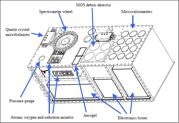
MEDET is a multi-disciplinary experiment, offering the opportunity for research in several areas of materials science and environmental effects. The instrument consists of a collection of active sensors and material samples, mostly exposed in the ram and zenith direction:
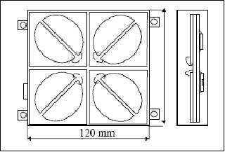
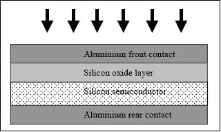
MOS debris detectors: The objective is to characterize microparticle impacts (number, size and velocity). The sensors are based upon the monitoring of the discharge of a parallel-plate capacitor using a thin dielectric. The device is operated with a bias voltage applied across the capacitor plates, so that a charge is normally stored in the capacitor. When a high velocity particle impacts the exposed plate with enough energy, it causes the dielectric to break down and the result is a discharge of the capacitor. The event is measured by monitoring the current required to recharge the capacitor. The sensitivity of the sensor depends mainly on the thickness of the top electrode and the dielectric.
A module made of 4 MOS detectors is being used in MEDET. The module requires power of 28 V for the command and data handling interfaces. Retrieval after exposure to space will allow a comparison of in-orbit detection data with actual impact features found on the device. This appraisal will be valuable for future improvement of detectors.
Aerogel (passive device): The objective is to collect micrometeoroid and debris particles for analysis after return of MEDET to Earth. Aerogel is an ultra-low density glass (typical density of 0.1 g cm-3), which can decelerate high velocity particles without totally vaporising them. The size of the Aerogel sample is 4 cm x 8 cm.
The chemical composition of the particulate residue left in the aerogel will be determined in order to differentiate between debris and micrometeoroids, and the angle and length of the tracks will also provide information about the original impact angle and velocity of the particles.
Transmission spectrometer: The objective is to measure the wavelength dependent degradation of transparent materials. A total of 22 transparent optical windows (including synthetic ultra-pure SiO2 and other radiation stable materials) are being placed on a rotating sample wheel on the ram face of MEDET. The sun is being used as a light source; space resistant optical fibers are being used to transmit the light through the windows to the miniature spectrometer modules. 39)
Two holes in the spectrometer wheel remain empty for reference reasons. An encoder system, consisting of photodiodes positioned under the wheel, are being used to identify the location of the wheel with respect to the fiberoptics at any given instant during the measurement sequence. The spectrometer modules are sensitive to the following spectral ranges: 190-735 nm (UV-VIS) and 350-1100 nm (VNIR), respectively.
Microcalorimeter: Fourteen space qualified microcalorimeters are used to follow the degradation of the thermo-optical properties of thermal control materials (TCC). Each calorimeter consists of a thermally insulated metal plate upon which the material to be tested is placed, using a technique such as vapor deposition, adhesive bonding or painting.
The temperature of the samples is measured using platinum resistance thermometers, and the equilibrium temperature variation for a given solar flux allows the variation in solar absorptance to be deduced. A black body calorimeter is used for reference purposes. The diameter of each calorimeter is 5.6 cm, with a sample diameter of 2.5 cm.
STORM (Southampton Transient Oxygen and Radiation Monitor) is an experiment developed by the University of Southampton. The objectives are to monitor the concentration of the atomic oxygen levels and the ultraviolet and X-rays emitted by the sun. 40)
The atomic oxygen (AO) sensor types are based on carbon film actinometers and thin-film zinc oxide (ZnO) detectors using the thin film resistance as the measurand. Both sensors are located on the ram-face of MEDET in an area close to the rotating spectrometer wheel. For the carbon film actinometers, the film resistance is expected to increase progressively as the carbon is eroded/oxidized by the AO. The principle of operation is similar to that of silver film actinometers flown on the STRV-1a mission.
The carbon actinometer instrument comprises four thin carbon films and an AD590 temperature sensor, all mounted on an alumina substrate the dimensions of which are 17 mm x 36 mm x 0.635 mm. Incorporated onto the substrate is a low power heater element that is being used to stabilize the film temperature since carbon exhibits a temperature dependent erosion rate.
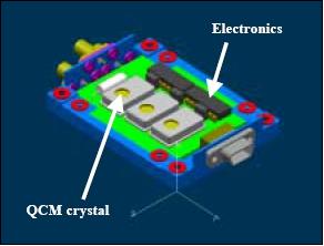
QCM (Quartz Crystal Microbalance) experiment: The objective is to measure the contamination levels and the atomic oxygen flux in the vicinity of the Space Station. The sensors are modified versions of commercially available miniature crystal oscillators. The quartz crystal is exposed to the space environment through a round hole in the housing directly above the crystal, and the oscillation frequency changes in relation to the changing mass and temperature of the crystal.
To measure the contamination flux, a bare crystal is used, and the oscillation frequency decreases as contamination is deposited on the surface of the crystal and the mass of the crystal increases. To measure the atomic oxygen flux, a carbon coated crystal is used, and the oscillation frequency increases as the atomic oxygen erodes away the carbon layer and the mass of the crystal decreases. For both of these techniques, the relationship between the mass of the crystal and the oscillation frequency can depend on the temperature of the crystal. Hence, a separate non-coated crystal cut in the "Y-direction" is also used to independently monitor the crystal temperature, so that the mass data can be corrected for temperature dependent effects.
The three types of sensors flown on board MEDET are:
- Type 1: 10 MHz Crystal with Au electrode for contamination deposition measurements. The sensitivity is 4.4 x 10⁻⁹ g cm-2 Hz-1.
- Type 2: 10 MHz Crystal with C-coating, to measure atomic oxygen. The sensitivity is 2.46 x 10¹⁵ O-atoms cm-2 Hz-1.
- Type 3: 11 MHz Crystal with Au electrode, for temperature measurements. The sensitivity is 600 Hz/K. The output of this type of crystal is being used to correct for temperature variations in Type 1 and Type 2.
Pressure gage: The objective is to monitor the local pressure. An adapted commercial cold cathode type pressure gage is being used to measure the local pressure. The characteristics of the instrument are:
- Pressure measurement range : 10-2 to 10-9 mbar
- Power consumption : 2 W
- Signal output : 0-10 V with 2 mV resolution.
PLEGPAY (Plasma Electrical Grounding Payload)
The goal of PLEGPAY is to validate the plasma contactor as an active device on the ISS for the prevention/control of electrostatic charging phenomena on large space structures orbiting at low Earth orbit.
The scientific objective of PLEGPAY experiment is the study of the spacecraft/space environment interactions in LEO, with reference to electrostatic charging/discharging phenomena. The spacecraft community is very interested to understand the mechanisms for electrostatic charge accumulation, which often produce uncontrollable discharge events, thereby adversely affecting the functioning of spacecraft electronic systems. Among the existing active methods to mitigate charging effects, the hollow cathode plasma contactor (an electric propulsion spin-off technology) has proved itself to be the most effective technology. A hollow cathode plasma contactor, as applied in PLEGPAY, and used to control the spacecraft charging in order to safeguard the spacecraft operation, could, in the near future, become a standard facility at disposal of the commercial and scientific satellites and space station/infrastructures. 41)
The PLEGPAY instrument was developed at Thales Alenia Space, under ASI contract.
Identification of the PLEGPAY Catastrophic Hazard 42)
EuTEF was intended to be operated continuously (24 hours a day, 7 days a week) for the 1.5 year period onboard the ISS, however things turned out differently. In July 2008, after several months of nominal EuTEF operations, the Boeing Space Environments Team announced that an unusual ISS floating potential was detected on July 17, 2008 by the FPMU (Floating Potential Measurement Unit). The FP (Floating Potential) is the difference in electrical potential between the ISS conducting structure and the surrounding ionospheric plasma.
The measured floating potential at the FPMU location was +24 V, whereas it should have been at near a 0 V level. While positive floating potentials have been observed in the past, they were restricted to levels less than +5V and were a result of special solar array orientations. Assessment of the PLEGPAY operations of July 17, 2008 correlated the change in ISS floating potential that day to PLEGPAY in "Plasma Contactor I-V characterization" mode, also known as "Experiment 1", i.e. biasing the plasma contactor w.r.t. the ISS structure and measuring the current exchanged with the space plasma.
Although PLEGPAY had not produced a violation of the ISS floating potential requirements, this factual proof of PLEGPAY's potential to affect the Station's FP alerted the ISS community, since a positive FP might have several implications to ISS operations.
First of all, positive FPs are identified as hazardous for EVAs (Extra Vehicular Activities): when the EVA crewmember contacts the ISS structure with a metallic part of the EMU (Extravehicular Mobility Unit), the electrical potential may arc through the crewmember, worst case resulting in loss of the EVA crew. Therefore, as a required hazard control, the NASA PCUs (Plasma Contactor Units) on the ISS are in discharge mode during EVA operations to ensure negative FPs. Operating PLEGPAY Experiment 1 during EVAs would interfere with the NASA PCU operations.
Secondly, the PLEGPAY Experiment 1 operations could have an impact to visiting vehicle (VV) operations due to EMI/EMC (electromagnetic interference/electromagnetic compatibility) effects and needed further assessment by specialists.
And thirdly, at the time of the event the ISS was certified for a FP range of ±40 V, but the total impact of having the ISS biased positive outside these limits on the ISS hardware was not exactly known and needed further assessment by specialists.
Given the complexity of the ISS plasma environment interactions and the need for further assessment by technical experts, NASA and ESA agreed at the end of July 2008 to inhibit PLEGPAY operations during EVA and visiting vehicle operations. The ISS operations teams in the Houston Mission Control Center (MCC-H), the Columbus Control Center (COL-CC) and the Erasmus USOC were informed about this constraint on PLEGPAY operations via a CHIT (the ‘ChitS' is a Mission Action Request (Chit) System, accessible by all ISS operators on ground) in anticipation of formal updates of the operational procedures, flight rules and hazard reports.
Events Leading to a Forced Shutdown of EuTEF (Ref. 42)
In the weeks following the above described event, the ISS safety community has been extremely solicited to assess the safety aspects of PLEGPAY operations. End of August 2008 the ISS PSRP (Payload Safety Review Panel) decided to classify PLEGPAY as a catastrophic hazard. For Shuttle and ISS payload safety, a hazard is defined critical when "the hazard can result in damage to STS/ISS equipment, a non-disabling personnel injury, or the use of unscheduled safety procedures that affect operations of the Orbiter (ISS) or another payload" and it is defined catastrophic when "the hazard can result in the potential for: a disabling or fatal personnel injury; or loss of the Orbiter (ISS), ground facilities, or STS/ISS equipment".
The ISS PSRP therefore concluded that PLEGPAY is a catastrophic hazard for EVAs (crew electrical shock hazard), visiting vehicle operations and nominal ISS operations (all ISS equipment is qualified against a FP of ±40V and further investigations on the effects of higher potentials were needed). According to safety requirements, catastrophic hazards require 3 independent inhibits to control the hazard (2 Fault Tolerant, 2 FT), while critical hazards require only two independent inhibits (1 Fault Tolerant, 1 FT).
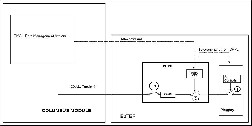
The ISS PSRP decision thus implied the necessity to have three independent inhibits to control the PLEGPAY hazard. The PLEGPAY instrument provided the first inhibit, the EuTEF DHPU (Data Handling and Power Unit) provided the second inhibit, but unfortunately the EuTEF/PLEGPAY electrical design did not have a third independent inhibit. The only option to control the hazard by three independent inhibits in series was to deactivate the operational power for the entire EuTEF platform, i.e. the 120 V Feeder No 1 coming from the Columbus module. Figure 31 depicts the three independent inhibits to control the PLEGPAY hazard.
Impact on EuTEF (Ref. 42)
The big drawback of the forced EuTEF Feeder No 1 shutdown was that besides PLEGPAY also the 7 other scientific and technology instruments on the platform did not receive operational power anymore. Luckily the EuTEF Feeder No 2 survival power from Columbus was still allowed such that power could be provided to the survival heaters of the platform and the instruments in order to keep them in the nominal temperature range and thus prevent potential hardware degradation due to a cold environment.
Several instruments onboard EuTEF had the science objective to run continuously during the 1.5 year on the ISS. Other instruments were intended to operate in a ‘campaign mode', i.e. alternating several hours/days of operations with several hours/days in standby mode. Especially for the group of instruments which needed continuous measurements the impact of the EuTEF Feeder No 1 shutdown on their science objectives was significant. Amongst those instruments were DOSTEL, EXPOSE-E and MEDET.
Lessons Learned from PLEGPAY Operations (Ref. 42)
The EuTEF shutdown for a period of two months, the PLEGPAY Experiment 1 removal and the resulting irrecoverable science loss due to these events could probably have been mitigated by a better vigilance on this matter and the timely consultation of the ISS experts during the development phase and the pre-launch flight safety reviews. "The NASA environments experts were not originally consulted by the safety review panel during the prelaunch flight safety reviews. Only subsequent to the identification of the potential for PLEGPAY to affect the ISS Floating Potential, the environments experts came to the safety panel to discuss the hazard potential and recommended operational controls."
TriboLab (Tribology Laboratory)
TriboLab is an investigation of the tribological (science of mechanisms of friction, lubrication, and wear of interacting surfaces that are in motion) behavior of different lubricants in microgravity which can not be simulated on Earth. The instrument (mass of 16 kg) was jointly developed by INTA (Madrid) and INASMET (San Sebastian), Spain.
The TriboLab instrument performs tests with different lubricants and different devices at basic and component level respectively: PoD (Pin-on-Disk) and BB (Ball Bearing). TriboLab is a tribometer, a device that measures the friction coefficient between two surfaces under the tribo-conditions investigated. The most usual tribometers measure only one sample at a time and the users change the new samples. 43)
TriboLab is meant to work without any action from the astronauts at the International Space Station. As more than one disk or ball bearing has to be tested, the concept of the instrument is that of a rack of experiments, which will be tested sequentially. Expected duration time of each experiment in space is between two and four weeks for the PoD and several months for the BB. This duration fits quite well with the expected time of the EuTEF mission (18 months), and materials will be studied after returning back to Earth.
References
1) M. Lachance, "Researchers Explore Materials Degradation In Space," Space Mart, March 31, 2008, URL: http://www.spacemart.com/reports/Researchers_Explore_Materials
_Degradation_In_Space_999.html
2) "STS-122: The Voyage of Columbus," NASA Press Kit, Feb. 2008, URL: http://www.nasa.gov/pdf/203212main_sts122_presskit2.pdf
3) Columbus Information Kit," ESA, January 2008, URL: http://esamultimedia.esa.int/docs/columbus/infokit/english/Columbus_infokit_changed_pages.pdf
4) "OasISS Information Kit," 'External Experiments: Solar Facility, EuTEF Facility,' ESA, May 2009, URL: http://esamultimedia.esa.int/docs/oasiss/05.OasISSInfoKit_EuroSciProgramme.pdf
5) P. Galeone, L. Péres Cuevas, G. Gianfiglio, "Watching the Sun," on Station no. 17, august 2004, URL: http://www.esa.int/esapub/onstation/onstation17/os17_chapter5.pdf
6) http://www.esa.int/esaMI/Columbus/SEMUKP8N9JF_0.html
7) http://www.esa.int/esaHS/SEMUKP8N9JF_research_0.html
8) F. Cometto, B. Musetti, P. Galeone, S. Salehi, "The SOLAR Payload Pointing Control System," Proceedings of the 7th International ESA Conference on Guidance, Navigation & Control Systems (GNC 2008), June 2-5, 2008, Tralee, County Kerry, Ireland
9) "State-of-the-art solar reference spectrum," ESA, 19 Dec. 2017, URL: http://m.esa.int/Our_Activities/Human_Spaceflight/Columbus/State-of-the-art_solar_reference_spectrum
10) "Solar on Columbus," ESA, 19 Dec. 2017, URL: http://m.esa.int/spaceinimages/Images/2017/12/Solar_on_Columbus
11) "Solar spectrum," ESA, 19 Dec. 2017, URL: http://m.esa.int/spaceinimages/Images/2017/12/Solar_spectrum
12) "Setting Sun on Space Station Solar research," ESA, Feb. 15, 2017, URL: http://m.esa.int/Our_Activities/Human_Spaceflight/Research/Setting_Sun
_on_Space_Station_Solar_research
13) Geraldine Mariën, Carla Jacobs, Alice Michel, Saliha Klai, Alexander Karl, Denis Van Hoof, Lode Pieters, "SOLAR: Wrap Up after 9 Years of Successful Operations on the ISS," Proceedings of the 68th IAC (International Astronautical Congress), Adelaide, Australia, 25-29 Sept. 2017, paper: IAC-17.B3.3.3
14) "Space Station Mercury," ESA, May 31, 2016, URL: http://m.esa.int/var/esa/storage/images/esa_multimedia/images/2016/05/space_station
_mercury/16010428-1-eng-GB/Space_Station_Mercury_article_mob.jpg
15) Carla Jacobs, Denis Van Hoof, Alejandro Sela, Saliha Klai, Alexander Karl, Leif Steinicke, Alice Michel, Nadia This, Christian Muller, Didier Moreau, "The SOLAR attitude for the International Space Station: from a one-time experimental attitude change request to a standard ISS attitude to advance SOLAR science," SpaceOps 2014, 13th International Conference on Space Operations, Pasadena, CA, USA, May 5-9, 2014, paper: AIAA 2014-1666, URL: http://arc.aiaa.org/doi/pdf/10.2514/6.2014-1666
16) "ESA ISS Science & System - Operations Status Report #146 Increment 36: 18-31May 2013 — SOLAR Facility," ESA June 10, 2013, URL: http://www.esa.int/Our_Activities/Human_Spaceflight/Columbus/ESA_ISS_Science_System
_-_Operations_Status_Report_146_Increment_36_18_31_May_2013
17) Carla Jacobs, Denis Van Hoof, Jean-Marc Wislez, Alejandro Sela, Alice Michel, Nadia This, Saliha Klai, Alexander Karl, Andrea Boyd, Didier Moreau, Christian Muller, Leif Steinicke, Gérard Thuillier, Thomas Foujols, David Bolsée, Thomas Foujols, Gerhard Schmidtke, Christian Erhardt, Bernd Nikutowski, Raimund Brunner, "Changing the ISS attitude to maximize the science return of the SOLAR payload,"Proceedings of the 64th International Astronautical Congress (IAC 2013), Beijing, China, Sept. 23-27, 2013, paper: IAC-13-B3.4-B6.5.2
18) "ESA ISS Science & System - Operations Status Report # 113 Increment 30," Feb. 24, 2012, URL: http://www.esa.int/esaMI/Columbus/SEMOLD7YBZG_0.html
19) "ISS Utilization - External Payloads," ESA Bulletin No 147, August 2011, p. 82
20) Martin Zell, Eric Istasse, Hilde Stenuit, Shankini Doraisingam, Josef Winter, Lina De Parolis, "Achievements, Plans and Outlook of the European ISS Utilization Program," Proceedings of the 61st IAC (International Astronautical Congress), Prague, Czech Republic, Sept. 27-Oct. 1, 2010, IAC-10.B3.3.1
21) Martin Zell, Eric Istasse, Hilde Stenuit, Shankini Doraisingam, Josef Winter, Lina De Parolis, "Achievements, Plans and Outlook of the European ISS Utilization," Proceedings of the 60th IAC (International Astronautical Congress), Daejeon, Korea, Oct. 12-16, 2009, IAC-09.B3.4.1
22) Ségolène Brantschen, L. De Smet, Alice Michel, "SOLAR Payload Operations: Achieving Flexibility to Support a Long Term Science Mission," Proceedings of the SpaceOps 2010 Conference, Huntsville, ALA, USA, April 25-30, 2010, AIAA 2010-1951
23) G. Schmidtke, C. Fröhlich, G. Thuillier, "ISS-SOLAR: Total (TSI) and spectral (SSI) irradiance measurements," Advances in Space Research, Volume 37, Issue 2, 2006, pp. 255-264
24) "The SOVIM Instrument," PMOD/WRC, URL: http://www.pmodwrc.ch/pmod.php?topic=space/sovim/index
25) G. Thuillier, D. Bolsee, D. Gillotay, "SOLSPEC on the International Space Station," 5th SORCE Science Meeting, Santa, Fee, NM, USA, Feb. 5-7, 2008, URL: http://lasp.colorado.edu/sorce/news/2008ScienceMeeting/doc/Session1/S1_04_Thuillier.pdf
26) F. G. Wienhold, J. Anders, B. Galuska, U. Klocke, M. Knothe, W. J. Riedel, G. Schmidtke, et al., "The Solar Package on ISS: SOL-ACES," Physical Chemistry of the Earth (C), Vol. 25, No 5-6, 2000, pp. 473-476
27) http://www.dlr.de/Portaldata/1/Resources/portal_news/newsarchiv2008_1/solaces_e.pdf
28) European Technology Exposure Facility (EuTEF)," ESA, March 3, 2010, URL: http://www.esa.int/SPECIALS/Columbus/SEM7ZTEMKBF_0.html
29) J. Kuitunen, G. Drolshagen, J. A. .M. McDonnell, H. Svedhem, M. Leese, H. Mannermaa, M. Kaipiainen, V. Sipinen, "DEBIE- First Standard In-Situ Debris Monitoring Instrument," Proceedings of the Third European Conference on Space Debris, March 19-21, 2001, Darmstadt, Germany. Ed.: Huguette Sawaya-Lacoste. ESA SP-473, Vol. 1, Noordwijk, Netherlands
30) G. Reitz, T. Berger, "Dosimetry Activities in the European Columbus Module onboard the ISS," Ionizing Radiation Detection and Data Exploitation Workshop, ESA/ESTEC, Oct. 17-18, 2007, URL: http://www.congrex.nl/07C37/Presentations/14_Reitz.pdf
31) G. Reitz, "European Dosimetry Activities for the ISS," 1st International Workshop on Space Radiation Research and 11th Annual NASA Space Radiation Health Investigators' Workshop, Arona (Italy), May 27-31, 2000, article in: Physica Medica - Vol. XVII, Supplement 1, 2001
32) G. Reitz, R. Beaujean, E. Benton, S. Burmeister, Ts. Dachev, S. Deme, M. Luszik-Bhadra, P. Olko, "Space radiation measurements on-board ISS -- the DOSMAP experiment," Radiation Protection Dosimetry, Vol. 116 (1-4), 2005, pp.374-379; doi:10.1093/rpd/nci262
33) http://www.efacec.pt/PresentationLayer/efacec_press_01.aspx?tipo=4&area=1&idioma=2&id=125
34) "Columbus camera captures first views of Earth," ESA, March 11, 2008, URL: http://www.esa.int/esaCP/SEMUW0M5NDF_index_0.html
35) "Columbus Mission Information Kit," ESA, January 2008, URL: http://esamultimedia.esa.int/docs/columbus/infokit/english/11_EuropeanExperimentProgramme_new.pdf
36) R. Förstner, "Entwicklung keramischer Festelektrolytsensoren zur Messung des Restsauerstoffgehalts im Weltraum," Thesis at IRS of the University of Stuttgart, Feb. 2003, URL: http://elib.uni-stuttgart.de/opus/volltexte/2003/1408/pdf/Diss_Foerstner.PDF
37) M. Dinguirard, J. C. Mandeville, M. Van Eesbeek, A. P. Tighe, C. Durin, A. Chambers, S. Gabriel, D. Goulty, G. Roberts, "Materials Exposure and Degradation Experiment (MEDET)," Conference and Exhibit on International Space Station Utilization - 2001, Cape Canaveral, FL, Oct. 15-18, 2001, AIAA 2001-5070, URL: http://esmat.esa.int/AIAA-2001-5070.pdf
38) A.P. Tighe, B.Iwanovsky, M. van Eesbeek, S. Duzellier, M. Dinguirard, D.Falguere, C. Pons, V. Inguimbert , V. Rejsek, C. Durin, J.C . Mandeville, S. Gabriel, D.Goulty, G.Roberts, "Overview of results from the Materials Exposure and Degradation Experiment (MEDET) after 18 months in orbit on the ISS," URL: http://esmat.esa.int/Materials_News/ISME09/pdf/10-In-flight/S12%20-%20Tighe.pdf
39) A. Cozzani, B. Sarti, G. Casarosa, F. Ratti, M. Appolloni, "Electromechanical design of a drive mechanism for the rotation of the spectrometer wheel inside MEDET experiment," Proceedings of the 10th European Space Mechanisms and Tribology Symposium, Sept. 24-26, 2003, San Sebastián, Spain, ESA SP-524
40) D. N. O. Goulty, C. B. White, S. B. Gabriel, G. T. Roberts, A. R. Chambers, J. N. Ross, (2006) "The Southampton Transient Oxygen and Radiation Monitor (STORM)," Proceedings of the 10th International Symposium on Materials in a Space Environment, Noordwijk, The Netherlands, ESA SP-616
41) G. Matticari, M. Materassi, G. E. Noci, A. Severi, J. Sabbagh, "PLEGPAY: A Plasma Contactor Experiment on the International Space Station," Proceedings of the 27th International Electric Propulsion Conference, Pasadena, CA, Oct. 15-19, 2001, URL: http://erps.spacegrant.org/uploads/images/images/iepc_articledownload_1988-2007/2001index/2002iepc/papers/t08/261_1.pdf
42) Tom Hoppenbrouwers, Zeholy Pronk, Giovanni Noci, "Operating Plasma Contactor Experiments Onboard the ISS – Lessons Learned from PLEGPay," Proceedings of the SpaceOps 2010 Conference, Huntsville, ALA, USA, April 25-30, 2010, paper: AIAA 2010-2378
43) J. Serrano, J. Gómez-Elvira, R. Santiago, J. Pazos, J. I. Oñate, I. Garmendia, A. Rodríguez, "TriboLab -A Space Tribometer (POSTER)," URL: http://www.esmats.eu/esmatspapers/pastpapers/pdfs/2001/serrano.pdf
The information compiled and edited in this article was provided by Herbert J. Kramer from his documentation of: "Observation of the Earth and Its Environment: Survey of Missions and Sensors" (Springer Verlag) as well as many other sources after the publication of the 4th edition in 2002. - Comments and corrections to this article are always welcome for further updates (eoportal@symbios.space).