ISS: Cupola
EO
ESA
Operational (nominal)
Quick facts
Overview
| Mission type | EO |
| Agency | ESA |
| Mission status | Operational (nominal) |
| Launch date | 08 Feb 2010 |
ISS Utilization: Cupola Observation Module of the ISS
Launch Cupola Imagery References
The European-built Cupola was added to the ISS in 2010 and continues to provide the best room with a view anywhere. In addition to serving as an observation and work area when the crew operates the Station’s robotic arms, it also provides excellent views of Earth, celestial objects and visiting vehicles.
The Cupola was provided by ESA to NASA in exchange for the transport of 5 external payloads (barter agreement). TAS-I (Thales Alenia Space-Italia) was the prime contractor of the Cupola (Italian for 'dome').
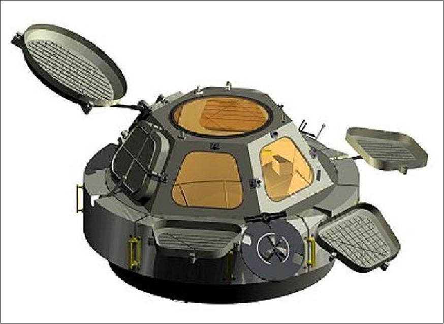
The Cupola is an aluminum structure of 2.95 m (max) in diameter, 1.5 m high with a mass of ~1800 kg. The Cupola is a “shirtsleeve” module with six trapezoidal side windows and a circular top window of 80 cm in diameter, making it the largest window ever flown in space (providing a panoramic view of Earth). Each window is built using very advanced technologies to defend the sensitive fused silica glass panes from years of exposure to solar radiation and debris impacts. 1)
The Cupola’s internal layout is dominated by upper and lower handrails supporting most of its equipment, and by closeout panels that cover the harness and the water lines attached to Cupola. These panels also provide air distribution to the outer structure and internal cabin. These panels are removable for inspection of the lower subsystems.
Parameter | Description |
Dimensions | - Diameter = 2.955 m; Including Micrometeoroid and orbital Debris Protection System with shutters closed |
Mass budget | - Launch mass = 1805 kg |
Communications and data infrastructure | - Via Audio Terminal Unit that is connected to Node 3 and the rest of the station |
Environmental control | - Environmental Control and Life Support air from Node Inter Module Ventilation |
Electrical power | - Direct from the Node 120 V interface: Window heaters |
Main construction material | - Dome: Forged Al 2219-T851 |
Hardware (primary) | - Forged/Machined Aluminum dome welded to skirt |
Hardware (secondary) | - Internal closure panels equipment & harness support brackets |
On-orbit configuration | - Transferred from Orbiter cargo bay to the Node location by the Shuttle Remote Manipulator System |
RWS (Robotic Work Station): The Copula hosts the RWS, allowing crewmembers to see Visiting Vehicles (VVs) – such as SpaceX’s Dragon – arrive for berthing, complimenting the camera views of their displays, allowing for increased situational awareness when operating the Station’s robotic assets.
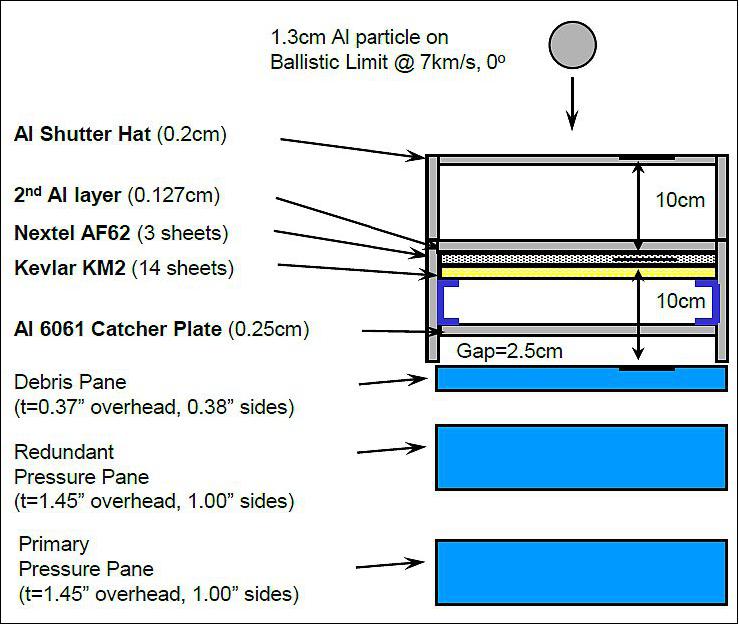
Cupola shutters: ISS Cupola windows have multi-layer Shutters that provide MMOD (Micrometeoroid and Orbital Debris) impact protection of the windows, when the shutters are closed. 5)
Background
Originally, at the time of the ‘Space Station Alpha’ plan, Boeing was in charge of the design and development of both elements under contract to NASA. The mid-1990, descoping of the Space Station Alpha concept led to the cancellation of the Cupola and forced NASA to find solutions to optimize the costs of essential elements such as the Nodes (Node-2 and Node-3, Ref. 1).
In 1997, NASA and ESA signed a barter agreement, known as the ‘Columbus Launch Offset Agreement’, or ‘Nodes Barter’, in which ESA would build Node-2 and Node-3 in exchange for the Shuttle launch of Columbus. This was a ‘win-win’ situation, as the money for the Columbus launch would be spent in Europe thus enhancing European industry’s know-how in human spaceflight engineering while NASA would acquire two modules without having to pay their development costs.
A couple of years later, another barter agreement with NASA was signed in which ESA agreed to provide Cupola in exchange for the launch and return with the Shuttle of five European payloads for Columbus.
Node-2 was delivered to Kennedy Space Center and the ownership transferred to NASA in June 2003. It has been operating in orbit for over a year following its launch with STS-120 on 23 October 2007. The Cupola was delivered to NASA in September 2004 and the ownership transferred to NASA in July 2005. It was stowed in the Space Station Processing Facility at Kennedy until spring 2008, when the final ground operation preparations for launch were started to be ready for the mating with Node-3 in spring 2009.
Node-3 development and AIT (Assembly, Integration and Testing) activities officially ended with a successful PAR (Preliminary Acceptance Review) held on 25 July 2007. From that moment on, it was supposed to be in storage until it was needed at Kennedy for launch processing; however, that plan did not really work because changes to the baseline continued to be introduced by NASA. The shipment of Node-3 to Florida is now planned for mid-April 2009.
Node-3 functions and layout: Node-3 is a pressurized cylinder with a diameter of 4.5 m and length almost 7 m. It can house up to eight ISS equipment racks and provides a pressurized passageway between berthed habitable volumes. It also accommodates the items necessary for the distribution of commands and data, audio, video, electrical power, atmosphere, water and thermal energy to adjacent elements. In addition, dedicated utilities are foreseen, to interface with special racks supporting crew habitability functions at station level.
The Node-3 architecture includes six ports with hatches, four radial and two axial. Three of the four radial ports and the nadir axial port are provided with Active Common Berthing Mechanisms for the berthing of attached elements, whereas the zenith port presents a Passive Common Berthing Mechanism.
Originally, the Habitation module, the Crew Return Vehicle and the PMA-3 (Pressurized Mating Adaptor 3) were also attached to Node-3 but the first two elements were deleted from the station configuration and the PMA-3 moved to Node-1 nadir port following the Node-3 relocation.
In its final location, the Cupola will be attached to the Node-3 nadir port i.e. facing Earth, and will provide the crew with a 360° panoramic view of the external surfaces of the ISS with exception of the zenith area.
The main functions of the Cupola are: panoramic control of ISS robotics and extravehicular activity operations (or ‘spacewalks’) by accommodation of the RWS (Robotic Work Station) and other items like sun visors; crew psychological and scientific observation of Earth; support of habitability by two crew members, i.e. air ventilation system, alarm annunciation and crew/ground communications through an ATU (Audio Terminal Unit), thermal control (provided by window heaters and water lines) and power and data distribution to portable items by implementing two Utility Outlet Panels.
Node-3 and Cupola on-orbit activation: Following launch and opening of the Shuttle’s cargo bay doors, the Node-3 heaters will be powered up to provide temperature control of the shell. During launch, Cupola is protected by a multi-layer insulation shroud covering the whole structure.
When the Shuttle berths to the PMA-2 docking port, the Shuttle crew will conduct a spacewalk to remove the cover of the Passive Common Berthing Mechanism and disconnect the power line used by Node-3 inside the Shuttle. The whole Node-3/Cupola assembly will be transferred by the ISS robotic arm to dock with the Node-1 port. The astronauts will then complete the first spacewalk by restoring power to the Node-3 heaters. Inside the ISS, the crew will then pressurize the area between Node-1 and Node-3, to open the Node-1 hatch, and perform utilities connections and fit out the area between the Nodes.
A second spacewalk will be performed to connect external power lines from the ISS truss to Node-3 and the ammonia lines for the thermal loop activation, plus other external outfitting tasks, such as the installation of handrails and Worksite Interfaces. Following this second spacewalk, the Node-3 system will be fully activated and the Node-3 hatch opened to allow the crew to enter the Node-3 cabin.
During the last part of the 20A flight, the crew will perform all the tasks required to prepare for moving Cupola to its final location, and then will perform the unberthing of Cupola. The ISS robotic arm will transfer and reberth the unpressurized Cupola to the Node-3 nadir port. The Cupola internal area will be pressurized and the Node-3 nadir hatch opened to allow the connection of electrical and water lines, the activation of window heaters, the assembly of the ATU (Audio Terminal Unit) and the two Utility Outlet Panels.
Other tasks, such as the filling of the water lines and the relocation of panels will be performed during this period. Once the heaters are activated, a spacewalk will be needed to remove and jettison the Cupola thermal shroud. From then on, the robotic workstation can be installed and the Cupola used by the crew to drive the robotic arm, monitor ATV and HTV berthing, make observations, or just relax and enjoy the view of Earth and the stars (Ref. 1).
Development Status
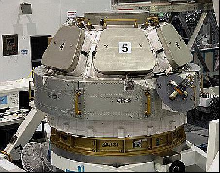
• On 31 August 2009 ESA engineers prepared the observation dome for transport to the International Space Station, where it will be joined to the Tranquility connecting module. The metal doors conceal six windows. 6)
• July 19, 2005: Ownership of the European-built Cupola observation module for the ISS was officially transferred to NASA on 7 July 2005. The signature, which took place at the Kennedy Space Center in Florida marks the conclusion of ESA’s obligations for the Cupola’s development as part of a bilateral barter agreement between ESA and NASA. 7)
- Under this agreement the European Space Agency provides the Cupola in exchange for Shuttle transportation services for European equipment and experiments for the Station.
- The Cupola is an observation and control tower for the International Space Station (ISS), with windows that provide a panoramic view through which operations on the outside of the Station can be observed and guided.
- It is a pressurised module that will accommodate command and control workstations and other hardware. This will allow crewmembers in the Cupola to control the Space Station’s robotic arm, which helps with the attachment and assembly of the various Station elements, and communicate with crewmembers in other parts of the Station or outside during spacewalk activities. The Cupola will further provide observational applications in the areas of Earth Observation and Space Science.
• A ceremony to mark the development phase completion of the Cupola was held in Turin, Italy, on September 6, 2004. The European-built Cupola provides a shirtsleeve working environment for two crewmembers. The ergonomically designed interior is equipped with workstations from which astronauts will be able to control the Station's robotic arm. 8)
- The completion of the cupola marks the end of the development phase of the project, which began with the signing of the cupola contract between ESA and Alenia Spazio on 8 February 1999. Under the contract, TAS-I (Thales Alenia Space-Italia), formerly Alenia Spazio, acted as prime contractor for production, responsible for coordinating six other firms: CASA (Spain), APCO (Switzerland), SAAB Ericsson and Lindholmen Development (Sweden), EADS Space Transportation (Germany) and Verhaert (Belgium).
Launch
Cupola was launched on Space Shuttle (Flight 20A/STS-130) on February 8, 2010 from KSC (Kennedy Space Center), Cape Canaveral, FL. The Cupola was launched inside the Orbiter cargo bay, mounted on a Spacelab pallet via a Manual Berthing Mechanism. The primary payload consisted of the Tranquility module and the Cupola. Tranquility, formerly known as Node-3, was the last element of a barter agreement by which ESA supplied NASA with ISS hardware, including the Cupola and two Node modules (Node 2 and 3). All elements were designed and built by TAS-I. In return, NASA ferried the European Columbus laboratory to the ISS in February 2008. 9) 10) 11)
Orbit: Near-circular orbit, altitude of ~ 400 km, inclination = 51.6º.
Mission Status
• April 27, 2023: The International Space Station (ISS) partners have agreed to extend the operational period of the ISS. The United States, Japan, Canada and participant European Space Agency (ESA) countries will support operations until 2030, while Russia has committed to continuing station operations until 2028. 33)
• November 2, 2020: Picturing Earth: Window On The World. 12)
• May 5, 2016: The European-built Cupola was added to the International Space Station in 2010 and continues to provide the best room with a view anywhere. — Its fused-silica and borosilicate-glass windows, however, sometime suffer from impacts by tiny artificial objects: space debris. 13)
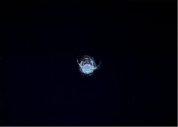
- ESA astronaut Tim Peake took this photo (Figure 5) from inside Cupola last month, showing a 7 mm diameter circular chip gouged out by the impact from a tiny piece of space debris, possibly a paint flake or small metal fragment no bigger than a few thousandths of a millimeter across. The background just shows the inky blackness of space. “I am often asked if the International Space Station is hit by space debris. Yes – this is the chip in one of our Cupola windows, glad it is quadruple glazed!” says Tim. To cater for such possibilities, the Station is provided with extensive shielding around all vital crew and technical areas, so that minor strikes, like this one, pose no threat.
- While a chip like the one shown here may be minor, larger debris would pose a serious threat. An object up to 1 cm in size could disable an instrument or a critical flight system on a satellite. Anything above 1 cm could penetrate the shields of the Station’s crew modules, and anything larger than 10 cm could shatter a satellite or spacecraft into pieces.
• January 2015: The large bay windows allow the Expedition 42 crew to see outside. The Cupola houses one of the space station's two robotic work stations used by astronauts to manipulate the large robotic arm seen through the right window. The robotic arm, or Canadarm2, was used throughout the construction of the station and is still used to grapple visiting cargo vehicles and assist astronauts during spacewalks. The Cupola is attached to the nadir side of the space station and also gives a full panoramic view of the Earth. 14)
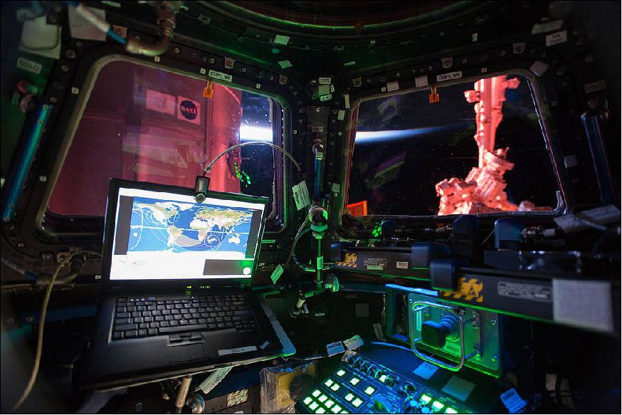
• Sept. 5, 2014: The MMOD (Micrometeoroid and Orbital Debris) strike on the Number 2 window of the International Space Station’s Cupola module appears to be contained within the debris pane, following evaluations by teams on the ground. The small, yet visible, damage to the window is not expected to impact on the operation of the Cupola – the Station’s main observation area and one of the star additions to the orbital outpost. 15)
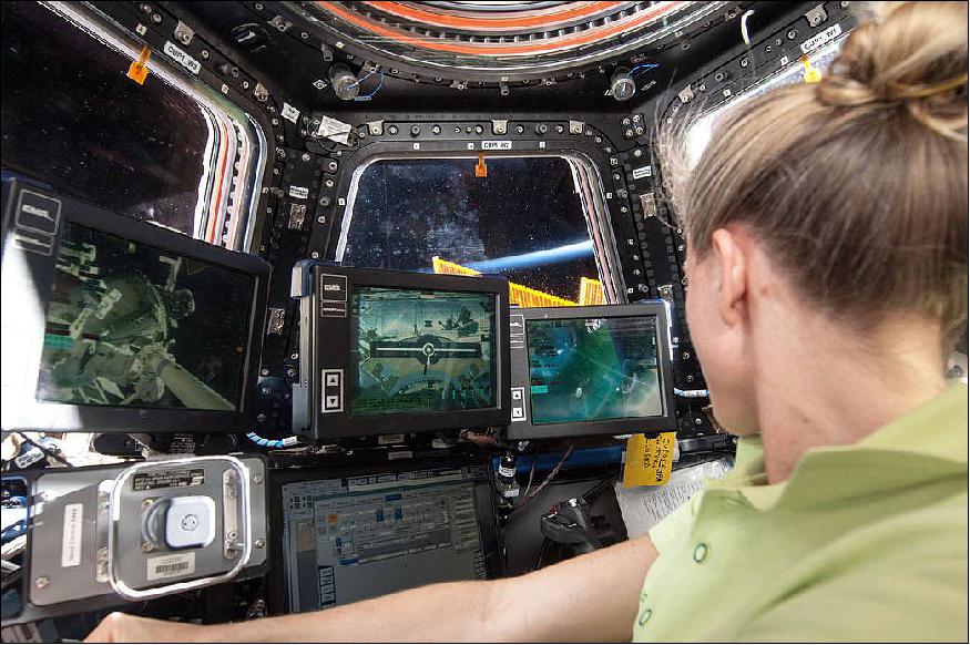
• August 9, 2013: At the robotics workstation in the International Space Station’s Cupola, NASA astronaut Karen Nyberg, Expedition 36 flight engineer, participates in onboard training activity in preparation for the grapple and berthing of the Japanese "Kounotori" H2 Transfer Vehicle-4 (HTV-4). The HTV-4 was installed on its berthing port on the Earth-facing side of the International Space Station’s Harmony node at 18:38 UTC on August 9, 2013, delivering 3.6 tons of science experiments, equipment and supplies to the orbiting complex. Nyberg and NASA astronaut Chris Cassidy grappled the HTV-4 with Canadarm2, the station's Canadian Space Agency-provided robotic arm, as the Japanese space freighter flew within about10 m of the complex. Flight Engineer Luca Parmitano of the European Space Agency joined the two NASA astronauts in the cupola to monitor the systems of the Japanese space freighter during its approach. 16)
• On July 21,2012, the HTV-3 (H-II Transfer Vehicle-3) of JAXA, nicknamed Kounotori-3 (White Stork), was launched from Japan with about 4600 kg of cargo. On arrival at the ISS, the capture of the HTV-3 was conducted from the Cupola control room as shown in Figure 10.
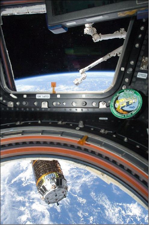
• On June 10, 2012, the ISS crew spotted a micrometeoroid impact on Cupola Window 2. The window was immediately shuttered and damage appears to be minor. 18) 19)
- MMOD (Micrometeoroid and Orbital Debris) impacts are part of life in low Earth orbit. Throughout the station, different shielding elements are applied to handle the inevitable impact from small orbital particles – too small to track and avoid. When not shuttered, the Cupola windows present a four layered front to potential impactors: a debris pane, two pressure panes, and an inner scratch pane. The windows are designed to be completely replaceable in the event of severe damage.
- Even all this shielding is not able to completely prevent ISS from showing signs of wear from its encounters with the flotsam and jetsam of space, hurtling through the barest wisps of atmosphere at thousands of kilometers per second. MMOD impacts occur all the time on ISS and other spacecraft, although most are not easily visible through a window. Returning Space Shuttles have shown pock marks from high velocity MMODs. The Space Shuttle Endeavor actually suffered a similar window impact on STS-126 which produced a hole in its thermal pane. Endeavour was able to reenter without heat damage and with no further propagation of the hole – although analysts initially thought some cracking might occur in the window, which was needed for pilot visibility during landing.
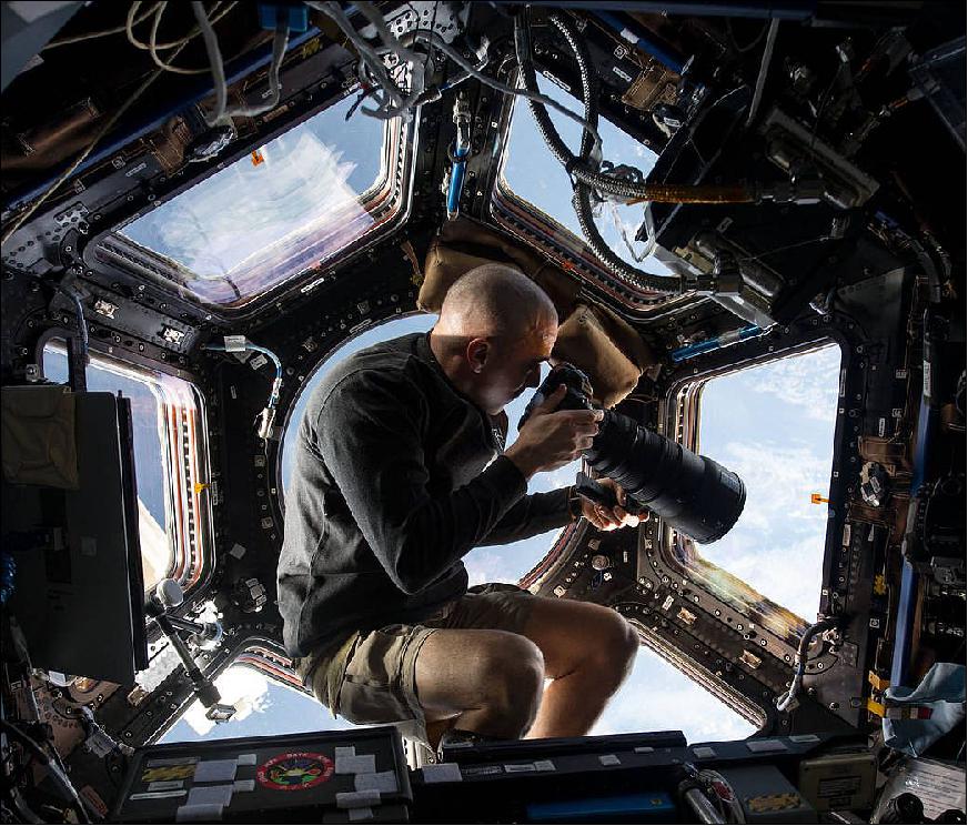
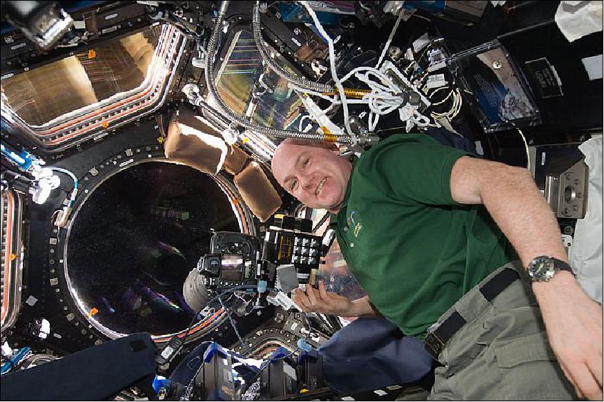
• February 2012: The NightPod, an automated tripod of ESA, was installed in the Cupola observatory. The NightPod camera-stand tracks the movement of Earth passing under the International Space Station at 28 800 km/h, keeping any target fixed in the middle of the viewfinder. Standard cameras fixed to NightPod can take pictures with longer exposure times so astronauts can take sharper pictures of cities at night. 20)
- The NightPod camera-stand tracks the movement of Earth passing under the International Space Station at 28 800 km/h, keeping any target fixed in the middle of the viewfinder. Standard cameras fixed to NightPod can take pictures with longer exposure times so astronauts can take sharper pictures of cities at night.
- The installation and commissioning of NightPod had been successfully completed on February 24, 2012 (Figure 11). The NightPod is part of the Crew standard training and will be operated by all Crew Members flying to the ISS in the coming years. 21)
- Note: A separate NightPod file is provided on the eoPortal under the heading ISS-NightPod.
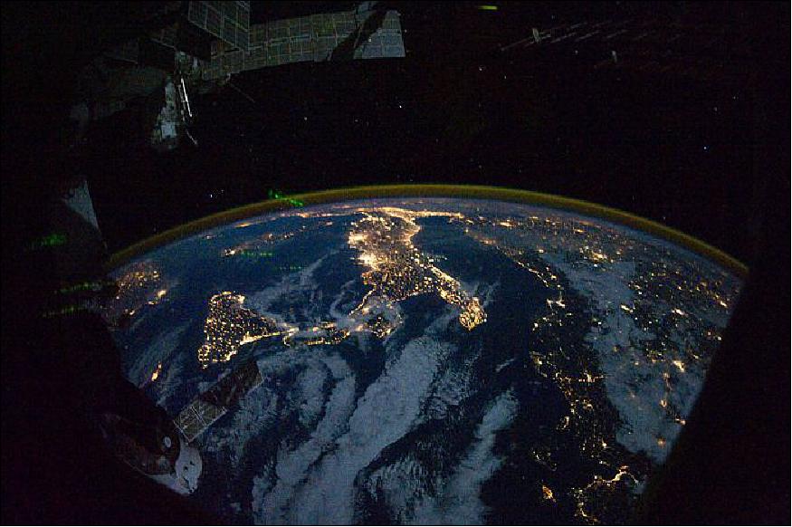
Legend to Figure 12: Parts of Europe and Africa are easily recognizable in this night image shot by one of the Expedition 25 crew members aboard the International Space Station flying 350 km above Earth on 28 October 2010. The view 'looks' northward over Sicily and the 'boot' of Italy, with the Mediterranean Sea representing most of the visible water in the view and the Adriatic Sea to the right of center. Tunisia is partially visible at left. Part of a docked Russian spacecraft and other components of the ISS are in the foreground. NASA photo ISS025-E-009840.
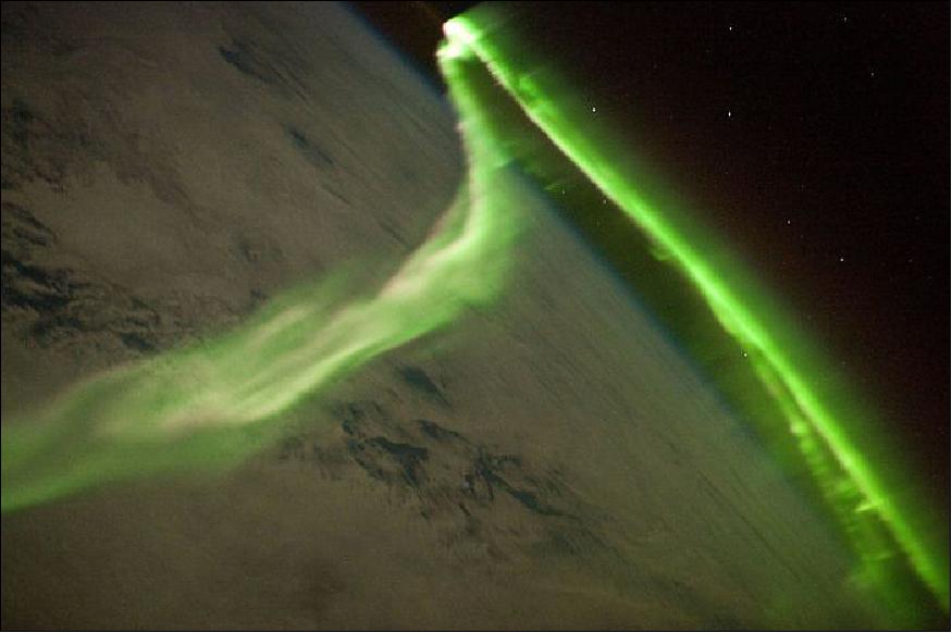
Legend to Figure 13: Among the views of Earth afforded crew members aboard the ISS, surely one of the most spectacular is of the aurora. These ever-shifting displays of colored ribbons, curtains, rays and spots are most visible near the North (Aurora Borealis) and South (Aurora Australis) Poles as charged particles streaming from the Sun (the solar wind) interact with Earth's magnetic field, resulting in collisions with atoms of oxygen and nitrogen in the upper atmosphere. The atoms are excited by these collisions, and typically emit photons as a means of returning to their original energy state. The photons form the aurora that we see. The most commonly observed color of aurora is green, caused by photons (light) emitted by excited oxygen atoms at wavelengths centered at 0.558 µm. Visible light is reflected from healthy (green) plant leaves at approximately the same wavelength. Red auroras are generated by light emitted at a longer wavelength (0.630 µm), and other colors such as blue and purple are also sometimes observed. While auroras are generally only visible close to the poles, severe magnetic storms impacting Earth's magnetic field can shift them towards the equator. This striking aurora image was taken during a geomagnetic storm that was most likely caused by a coronal mass ejection from the Sun on 24 May 2010. The ISS was located over the Southern Indian Ocean at an altitude of 350 km, with the observer most likely looking towards Antarctica (not visible) and the South Pole. The aurora has a sinuous ribbon shape that separates into discrete spots near the lower right corner of the image. While the dominant coloration of the aurora is green, there are faint suggestions of red photon emission as well (light fuscia tones at center left). Dense cloud cover is dimly visible below the aurora. The curvature of Earth's horizon is clearly visible as is the faint blue line of the upper atmosphere directly above at top center. Several stars appear as bright pinpoints against the blackness of space at top right. NASA photo ISS023-E-058455.
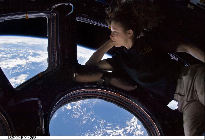
• Sept. 11, 2010: NASA astronaut Tracy Caldwell Dyson, Expedition 24 flight engineer, looks through a window in the Cupola of the International Space Station. A blue and white part of Earth and the blackness of space are visible through the windows. The image was a self-portrait using natural light. 24)
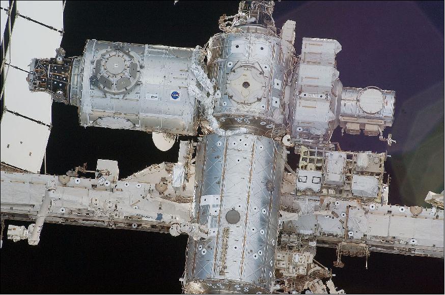
• Feb. 19, 2010: A close-up view of a portion of the International Space Station is featured in Figure 15 photographed by an STS-130 crew member on space shuttle Endeavour after the station and shuttle began their post-undocking relative separation. Undocking of the two spacecraft occurred at 14:54 UTC on Feb. 19, 2010. The newly-installed Tranquility node and Cupola are visible at top left. 25) 26)
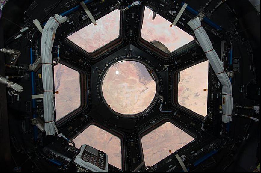
• Figure 16 is the first image taken through a first of its kind, a 'bay window' on the International Space Station — when the Cupola opened its seven eyelids on February 17, 2010. 27)
- Japanese astronaut Soichi Noguchi took this view from inside the cupola just after its windows were first opened on Feb. 17, 2010. The cupola's window shutters are open and the Sahara desert is visible below. 28)
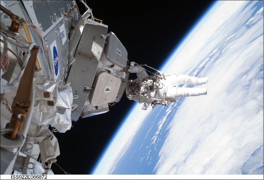
• Feb. 17, 2010: NASA astronaut Nicholas Patrick, STS-130 mission specialist, participates in the mission's third and final session of extravehicular activity (EVA) as construction and maintenance continue on the International Space Station (Figure 17). During the five-hour, 48-minute spacewalk, Patrick and astronaut Robert Behnken (out of frame), mission specialist, completed all of their planned tasks, removing insulation blankets and removing launch restraint bolts from each of the Cupola's seven windows. 29)
- The Cupola’s seven windows were exposed to space for the first time during STS-130’s EVA-3, following the removal of the module’s MLI blanket insulation by spacewalkers Bob Behnken and Nick Patrick. 30)
• Node 3 was attached to the port side of Node 1 (Unity Module), and the Cupola was berthed on its nadir (Earth facing) port (Figure 18). Node 3 is providing accommodation for life-support and exercise equipment. It accommodates ISS air revitalization, oxygen generation, carbon dioxide removal and water recovery systems. It also contains the bathroom for the crew hygiene and exercising equipment such as a treadmill and a weight-lifting device.
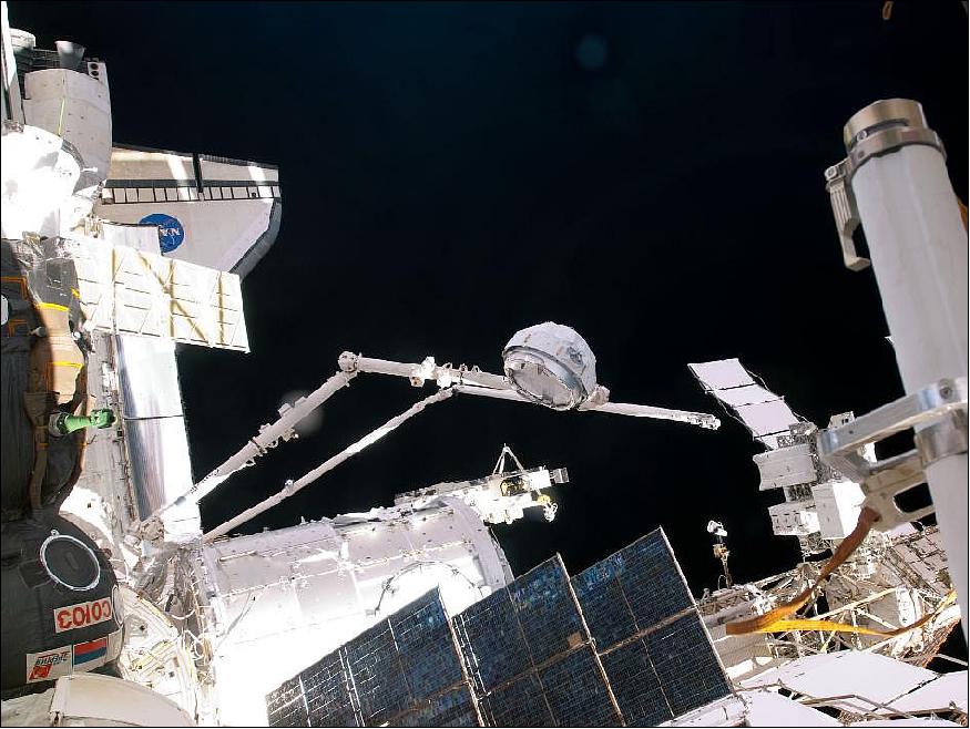
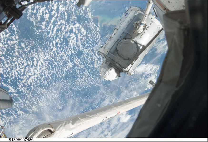
• Feb. 11, 2010: In the grasp of the International Space Station's Canadarm2, the Tranquillity module is transferred from its stowage position in Space Shuttle Endeavour's payload bay during STS-130 to position it on the port side of the Unity node of the ISS (Figure 19). Tranquillity was locked in place with 16 remotely-controlled bolts. 31)
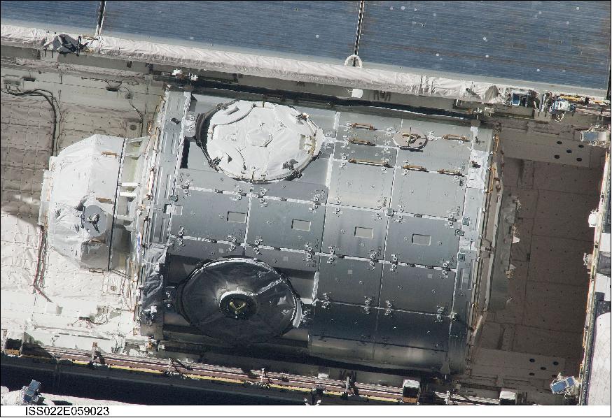
• This high- angle 800 mm image (Figure 20) of the Tranquility Node/Node 3 in space shuttle Endeavour's cargo bay was photographed by an Expedition 22 crew member aboard the ISS. The two spacecraft (Copula mode at left) were in the process of their rendezvous activities which included a back-flip by Endeavour. Tranquility will be installed as the third node for the orbital outpost. It has a length of 6.7 m, a diameter of 4.3 m, and a mass of 17,998 kg. 32)
References
1) Philippe Deloo, Sara Pastor, ”ESA's room with a view — Node-3 and Cupola ready for launch,” ESA Bulletin No 137, February 2009, pp:60-67, URL: http://www.esa.int/esapub/bulletin/bulletin137/bul137h_deloo.pdf
2) ”Cupola observation module,” ESA, Nov. 13, 2013, URL: http://www.esa.int/Our_Activities/Human_Spaceflight/International_Space_Station/Cupola
3) ”Cupola observation module,” ESA, URL: http://www.esa.int/Our_Activities/Human_Spaceflight/International_Space_Station/Cupola
4) ”Cupola Observation module factsheets,” ESA, Document No ESA-HSO-COU-004, URL: http://wsn.spaceflight.esa.int/docs/Factsheets/4%20Cupola%20HR%20web.pdf
5) Eric Christiansen, ”MMOD Protection and Degradation Effects for Thermal Control Systems,” NASA, August 2014, URL: https://tfaws.nasa.gov/wp-content/uploads/MMOD_Course_TFAWS_2014.pdf
6) ”An all-round view in space: Panoramic dome on its way to the ISS,” DLR News Archive Feb. 8, 2010, URL: http://www.dlr.de/iss/en/DesktopDefault.aspx
/tabid-6220/10231_read-22332/gallery-1/gallery_read-Image.1.13039/
7) ”ESA transfer ownership of European-built ISS observation module to NASA,” ESA, July 19, 2005, URL: http://www.esa.int/Our_Activities/Human_Spaceflight/
International_Space_Station/ESA_transfer_ownership_of_European-built_ISS_observation_module_to_NASA
8) ”Largest window for space completed,” ESA, Sept. 9, 2004, URL: http://www.esa.int/Our_Activities/Human_Spaceflight/
International_Space_Station/Largest_window_for_space_completed
9) http://www.nasa.gov/pdf/420302main_sts130_press_kit.pdf
10) Philippe Deloo, Sara Pastor, “ISS Hardware Handover, Transferring ownership of Node-3 (with Cupola attached),” ESA Bulletin Nr 141, Feb. 2010, pp. 38-45
11) “Cupola: a window over the Earth,” TAS-I, URL: https://web.archive.org/web/20131207132529/http://thalesaleniaspace-issmodules.com/index.php/cupola
12) ” Picturing Earth: Window On The World,” NASA Earth Observatory, 2 November 2020, URL: https://earthobservatory.nasa.gov/features/videos/window-on-the-world
13) ”Impact chip,” ESA, May 5, 2016, URL: http://www.esa.int/spaceinimages/Images/2016/05/Impact_chip
14) Sarah Loff, ”Interior View From the International Space Station Cupola,” NASA, July 31, 2015, URL: http://www.nasa-usa.de/content/interior-view-from-the-international-space-station-cupola
15) Chris Bergin, ”ISS teams evaluate MMOD strike on Cupola window,” NASA Spaceflight.com, Sept. 5, 2014, URL: http://www.nasaspaceflight.com/2014/09/iss-evaluate-mmod-strike-cupola-window/
16) ”Robotics Workstation in the International Space Station’s Cupola,” NASA, Aug. 9, 2013, URL: http://www.nasa.gov/content/robotics-workstation-in-the-international-space-station-cupola
17) ”Targeting Earth Photographs From Orbit,” NASA, June 10, 2013, URL: http://www.nasa.gov/multimedia/imagegallery/image_feature_2527.html
18) Merryl Azriel, ”Micrometeoroid hit ISS Cupola,” Space Safety Magazine, June 14, 2012, URL: http://www.spacesafetymagazine.com/space-debris/kessler-syndrome/micrometeroid-hit-iss-cupola/
19) Chris Bergin, ”Cupola hit by minor MMOD strike, shutter closed for evaluations,” NASA Spaceflight.com, June 12, 2012, URL: https://www.nasaspaceflight.com/
2012/06/cupola-minor-mmod-strike-shutter-closed-evaluations/
20) Massimo Sabbatini, Luigi Castiglione, “NightPOD - Capturing Earth by night from space,” ESA Bulletin, No 155, August 2013, pp. 46-55
21) Luigi Castiglione, Simon Silvio Conticello, Marco Esposito, Rody Oldenhuis, Scott G. Moon, Anja Nicolai, Stephan Stoltz, Jan Dettmann, “The NightPod – An orbital motion compensation mechanism for ISS based imaging,” Proceedings of the 63rd IAC (International Astronautical Congress), Naples, Italy, Oct. 1-5, 2012, paper: IAC-12-B3.3.12
22) ”Nightly view of Europe and Africa,” ESA, Nov. 16, 2010, URL: http://www.esa.int/spaceinimages/Images/2010/11/Nightly_view_of_Europe_and_Africa
23) ”Aurora Australis,” ESA, released on Nov. 17, 2010, URL: http://www.esa.int/spaceinimages/Images/2010/11/Aurora_Australis
24) ”International Space Station Imagery,” NASA, Sept. 11, 2010, URL: http://spaceflight.nasa.gov/gallery/images/station/crew-24/html/iss024e014263.html
25) ”STS-130 Shuttle Mission Imagery,” NASA, Feb. 19, 2010, URL: http://spaceflight.nasa.gov/gallery/images/shuttle/sts-130/html/s130e012251.html
26) ”Reference guide to the International Space Station,” NASA Utilization Edition, Sept. 2015, URL: http://www.nasa-usa.de/sites/default/files/atoms/
files/np-2015-05-022-jsc-iss-guide-2015-update-111015-508c.pdf
27) ”ISS022E066972 Cupola on ISS extviews - 4,” ESA, released on Feb. 18, 2010, URL: http://www.esa.int/spaceinimages/Images/2010/02/iss022e066972_Cupola_on_ISS_extviews_-_4
28) Tariq Malik, ”Astronauts Bask in Spectacular Views From New Space Windows,” Space.com, Feb. 16, 2010, URL: http://www.space.com/7932-astronauts-bask-spectacular-views-space-windows.html
29) https://en.wikipedia.org/wiki/Tranquility_%28ISS_module%29#/
media/File:STS-130_EVA3_Nicholas_Patrick_iss022e066872_full_view_crop.jpg
30) Chris Bergen, ”STS-130: EVA-3 marks Cupola’s grand opening – Comm issues evaluated,” NASA Spaceflight.com, Feb. 16, 2010, URL: https://www.nasaspaceflight.com/
2010/02/sts-130-eva-3-cupolas-opening-comm-issues-evaluated/
31) ”STS-130 Shuttle Mission Imagery,” NASA, Feb. 11, 2010, URL: http://spaceflight.nasa.gov/gallery/images/shuttle/sts-130/html/s130e007486.html
32) ”International Space Station Imagery,” NASA, Feb. 9, 2010, URL: http://spaceflight.nasa.gov/gallery/images/station/crew-22/html/iss022e059023.html
33) Garcia, Mark. “Partners Extend International Space Station for Benefit of Humanity – Space Station.” NASA Blogs, 27 April 2023, https://blogs.nasa.gov/spacestation/2023/04/27/partners-extend-international-space-station-for-benefit-of-humanity/
The information compiled and edited in this article was provided by Herbert J. Kramer from his documentation of: ”Observation of the Earth and Its Environment: Survey of Missions and Sensors” (Springer Verlag) as well as many other sources after the publication of the 4th edition in 2002. - Comments and corrections to this article are always welcome for further updates (eoportal@symbios.space).