IRS-P6 (Indian Remote-Sensing Satellite-P6)
EO
Mission complete
Imaging multi-spectral radiometers (vis/IR)
High resolution optical imagers
Indian Remote-Sensing Satellite-P6 (IRS-P6), renamed ResourceSat-1, was an optical imaging satellite operated by the Indian Space Research Organisation (ISRO). As the last satellite of the IRS series, it monitored the natural resources and environments of India from its launch in October 2003 until its operation ended in 2013.
Quick facts
Overview
| Mission type | EO |
| Agency | ISRO |
| Mission status | Mission complete |
| Launch date | 17 Oct 2003 |
| End of life date | 07 Dec 2013 |
| Measurement domain | Land, Snow & Ice |
| Measurement category | Multi-purpose imagery (land), Vegetation, Albedo and reflectance, Landscape topography, Sea ice cover, edge and thickness, Snow cover, edge and depth |
| Measurement detailed | Land surface imagery, Vegetation type, Earth surface albedo, Land surface topography, Snow cover, Fraction of Absorbed PAR (FAPAR), Glacier cover |
| Instruments | LISS-III (Resourcesat), AWiFS, LISS-IV |
| Instrument type | Imaging multi-spectral radiometers (vis/IR), High resolution optical imagers |
| CEOS EO Handbook | See IRS-P6 (Indian Remote-Sensing Satellite-P6) summary |
Related Resources
Summary
Mission Capabilities
ResourceSat-1 carried an Advanced Wide Field Sensor (AWiFS) - a type of imaging multispectral radiometer, as well as a medium-resolution and a high-resolution multispectral camera: Linear Imaging Self-Scanning Sensor-3 (LISS-3) and Linear Imaging Self-Scanning Sensor-4 (LISS-4). All instrument data was used for studying crop yield, pest/disease surveillance, disaster management, as well as land and water resource management.
Performance Specifications
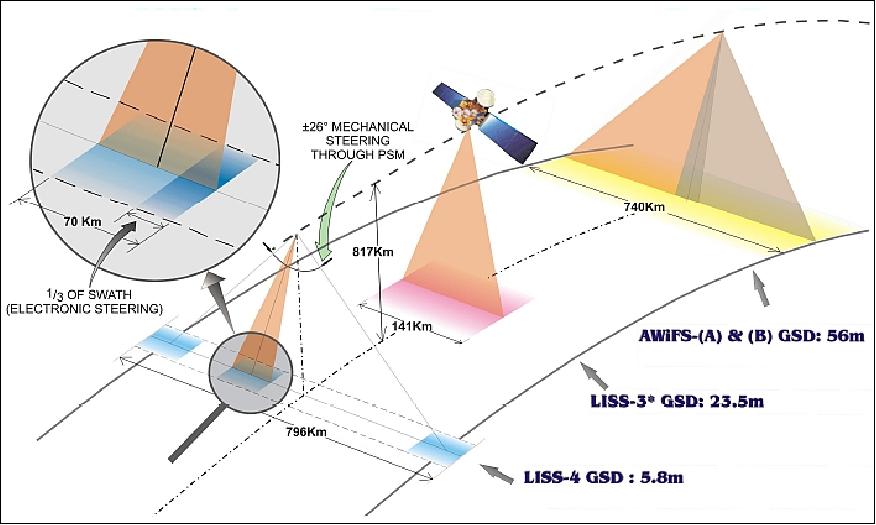
AWiFS had a swath width of 740 km with a spatial resolution of 56 - 70 m (nadir-swath edge) and observed in four spectral bands: green, red, Near Infrared (NIR), and Short Wave Infrared (SWIR). LISS-3 also observed in four bands (green, red, NIR, and SWIR) but with a swath width of 141 km and resolution of 23.5 m. LISS-4 featured a multispectral mode and a Mono mode which both imaged in three bands (green, red, and NIR) at a resolution of 5.8 m, and a swath width of 23.9 km and 70 km respectively.
ResourceSat-1 followed a sun-synchronous orbit with an altitude of 817 km and an inclination of 98.7°. It had a period of 101.35 minutes and a repeat cycle of 24 days.
Space and Hardware Components
Telemetry, Tracking, and Command (TT&C) communications were transmitted via S-band radio frequencies with a downlink rate of 1-16 kbit/s and an uplink rate of 100 bit/s. Payload data was transmitted in X-band at a rate of 105 Mbit/s.
ResourceSat-1 — formerly IRS-P6 (Indian Remote-Sensing Satellite-P6)
Overview Spacecraft Launch Mission Status Sensor Complement Ground Segment References
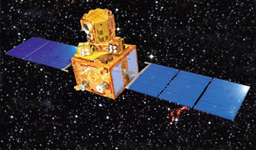
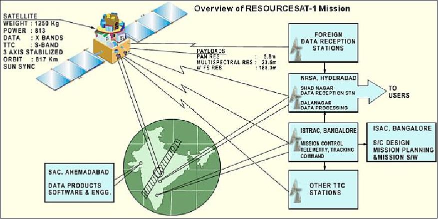
IRS-P6 is an Earth observation mission within the IRS (Indian Remote-Sensing Satellite) series of ISRO (Indian Space Research Organization), Bangalore, India. The overall objectives of the IRS-P6 mission (ResourceSat-1) are to provide continued remote sensing data services on an operational basis for integrated land and water resources management. IRS-P6 is the continuation of the IRS-1C/1D missions with considerably enhanced capabilities. 1)
Prior to launch, ISRO renamed the IRS-P6 spacecraft to ResourceSat-1, to describe more aptly the application spectrum of its observation data.
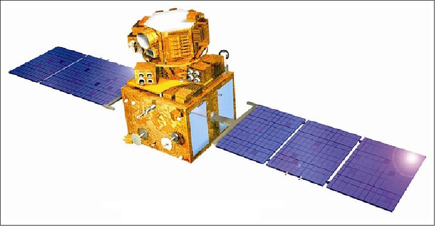
Spacecraft
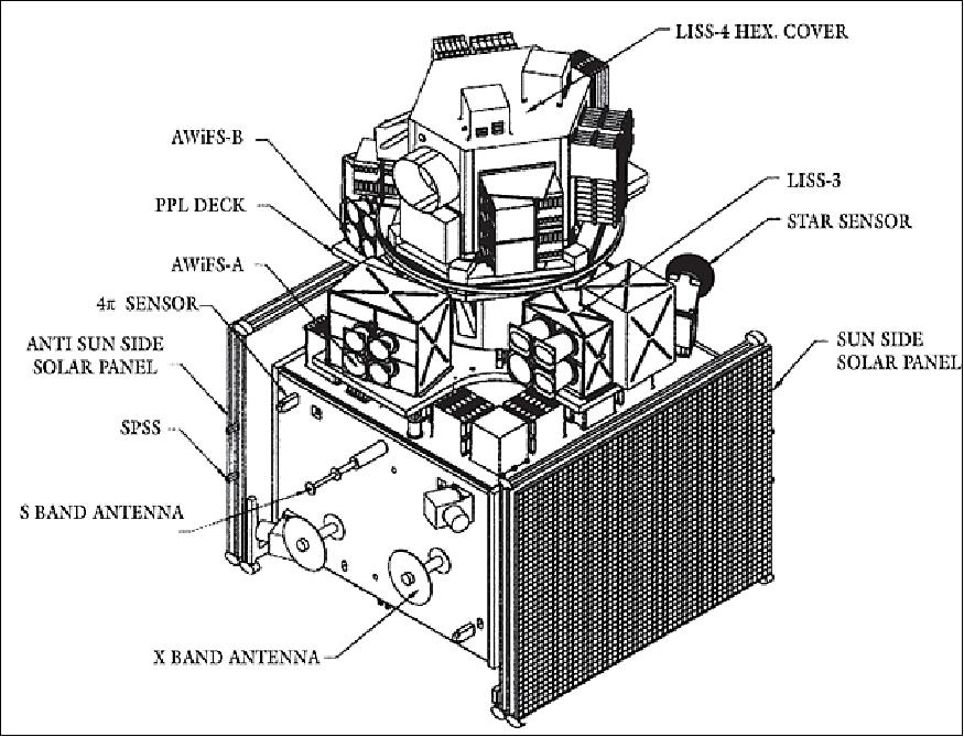
The S/C mainframe is of IRS-1C/1D -P3 heritage (built by ISRO/ISAC, Bangalore). The S/C structure consists of two modules, the main platform and the payload module. The main platform is built around a central load bearing cylinder of 915 mm diameter and consists of four vertical panels and two horizontal decks. The bottom of cylinder is attached to an interface ring which interfaces with the launch vehicle. The vertical panels and the horizontal decks carry various subsystem packages. Various attitude sensors, SPS (Satellite Positioning System) and data transmitting antennas are mounted on the outside surfaces of the equipment panels and the bottom deck. Two star trackers are mounted with skewed orientation on the top deck. The payload module in turn is comprised of a two-tier system, the payload module deck and the rotating deck. The payload module deck accommodates LISS-3, AWIFS-A and AWIFS-B camera modules.
The LISS-4 camera is mounted on a rotating deck which is attached to a PSM (Payload Steering Motor) which can rotate by ± 26º. The entire payload module assembly is attached to a CFRP monocoque cylinder, which in turn is attached to the main cylinder of the main platform through a strut assembly for effective load transfer. 2)
The overall S/C size is about 2 m in diameter and 2.1 m in height. The total S/C mass at launch is 1360 kg, including fuel for five years of operation. Power is provided by a solar array generating 1250 W (EOL), the array is articulated into the sun; in addition there are 2 NiCD batteries with a capacity of 24 Ah each. 3)
The platform is three-axis stabilized [2 star sensors in loop, magnetic bearing reaction wheels, RCS (Reaction Control System) with 12 nozzles, 8 with 1 N thrusters, 4 nozzles with 11 N thrusters], the pointing accuracies are ±0.15º, the stability is 3 x 10⁻⁴ º/s. An onboard solid-state recorder (SSR) provides 120 Gbit capacity to store about 20 minutes of LISS-4 data. The S/C design life is 5 years.
RF communications: TT&C communications in S-band with downlink data rates of 1-16 kbit/s; modulation: PCM/PSK/PM. The uplink data rate is 100 bit/s. The TT&C transponder transmits the telemetry data, receives the telecommand signals, demodulate the ranging tones and re-transmits them to ground with a fixed turnaround ratio of 240/221 for two-way ranging (Doppler measurement). Uplink frequency: 2071.875 MHz, downlink frequency: 2250 MHz.
The payload data are transmitted in X-band at a data rate of 105 Mbit/s. The BDH (Baseband Data Handling) system consists of two separate chains, one for LISS-3 and AWiFS data, and the second chain for LISS-4 data. The LISS-4 data are transmitted on carrier-1 at 8125 MHz and LISS-3 + AWiFS data are transmitted on carrier-2 at 8300 MHz.
Launch: A launch of the IRS-P6 satellite took place Oct. 17, 2003 on a PSLV launcher from SHAR (Satish Dhawan Space Centre, Sriharikota), India.
Orbit: Sun-synchronous orbit, altitude = 817 km, inclination = 98.69º, period = 101.35 min, local time of equator crossing at 10:30 hours on LTDN (Local Time on Descending Node). The ground track is maintained within ± 1 km.
The achieved IRS-P6 injected orbit was estimated as 815.417 km x 831.668 km with an inclination of 98.805º.The target orbit was achieved by performing three in-plane and five combined (in-plane and out-of-plane) maneuvers. A total of eight orbit acquisition maneuvers, starting from Oct. 20 to Nov. 29, 2003 were performed for obtaining "locked-path" and "frozen-perigee" orbits. Path locking was done on Nov. 29, 2003. 4)
Mainframe system | - Al and Al honeycomb structure with CFRP elements for main platform and payload modules |
Thermal control | Passive, semi-active and active elements like OSR (Optical Solar Reflectors), MLI (Multi-Layer Insulation), heat pipes, tape/foil heaters etc,. |
Power system |
|
AOCS |
|
Mission Status
• December 2015: According to the ISRO Country Report to APRSF 2015, ResourceSat-1 is operational. - The LISS-4 instrument has a reduced capacity since 2012. 5)
• ResourceSat-1 was launched on 17 October, 2003 and continues to provide remote sensing data services in October 2014 (11 years on orbit). 6)
• In 2012, the ResourceSat-1 (alias IRS-P6) is operational with reduced capacity (Ref. 8). ResourceSat-1 is in its 9th year of operations. The LISS-3 and AWiFS payloads are operated routinely. 7)
• IRS-P6 and its payload are operating nominally in February 2011 (in its 8th year on orbit). 8)
• IRS-P6 and its payload are operating nominally in 2010 9)
• IRS-P6 and its payload are operating nominally in 2008 and in 2009.
• In 2007, cross-calibrations of the IRS-P6 sensors (AWiFS, LISS-3) were performed with ETM+ of Landsat-7, TM of Landsat-5, and the HRCCD of CBERS-2. 10) 11)
Sensor Complement
ResourceSat-1 carries three instruments: 12) 13)
• A high resolution linear imaging self-scanner (LISS-IV)
• A medium resolution linear imaging self-scanner (LISS-III)
• AwiFS (Advanced Wide Field Sensor).
All three cameras are pushbroom scanners using linear arrays of CCDs (Charge Coupled Devices).
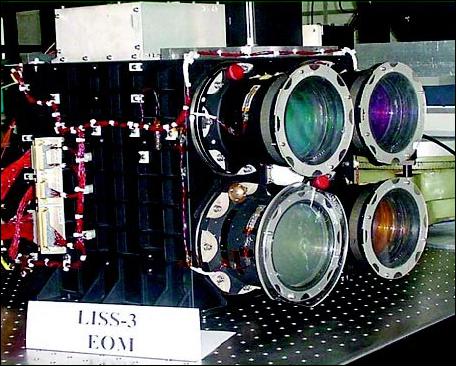
LISS-4 (Linear Imaging Self-Scanning Sensor-4)
The LISS-4 multispectral high-resolution camera is the prime instrument of this sensor complement. LISS-4 is a three-band pushbroom camera of LISS-3 heritage (same spectral VNIR bands as LISS-3) with a spatial resolution of 5.8 m and a swath of 70 km. LISS-4 can be operated in either of two support modes: 14)
• Multispectral (MS) mode: Data is collected in 3 bands corresponding to pre-selected 4096 contiguous pixels with a swath width of 23.9 km (selectable out of 70 km total swath). The 4 k detector strip can be selected anywhere within the 12 k pixels by commanding the start pixel number using the electronic scanning scheme.
• Mono mode: Data of the full 12 k pixels of any one single selected band, corresponding to a swath of 70 km, can be transmitted. Nominally, band-3 data (B3) are being observed and transmitted in this mode.
LISS-4 features in addition a ±26º steering capability in the cross-track direction permitting a 5-day revisit cycle. The optoelectronic module of LISS-4 is identical to that of the PAN camera of IRS-1C/1D. The CCD array features 12,288 elements for each band. The instrument has a mass of 169.5 kg, power of 216 W, and a data rate of 105 Mbit/s. The detector temperature control is implemented using a radiator plate coupled to each band CCD through heat pipes and copper braid strips.
The LISS-4 camera is realized using the three mirror reflective telescope optics (same as that of the PAN camera of IRS-1C/1D) and 12,288 pixels linear array CCDs with each pixel of the size 7 µm x 7 µm. Three such CCDs are placed in the focal plane of the telescope along with their individual spectral bandpass filters. An optical arrangement comprising an isosceles prism is employed to split the beam into three imaging fields which are separated in the along track direction. The projection of this separation on ground translates into a distance of 14.2 km between the B2 and B4 image lines. While B3 is looking at nadir, B2 is looking ahead and B4 is looking behind in the direction of velocity vector. Detector type: THX31543A of Thomson.
LISS-4 calibration: An in-flight calibration scheme is implemented using LEDs (Light Emitting Diodes). Eight LEDs positioned in front of the CCD (without obstructing the light path during imaging). These LEDs are driven with a constant current and the integration time is varied to get 16 exposure levels, covering the dynamic range in a sequential manner. This sequence repeats in a cyclic form.
LISS-3 (Linear Imaging Self-Scanning Sensor-3)
LISS-3 is a medium-resolution multispectral camera. The pushbroom instrument is identical to LISS-3 on IRS-1C/1D (with regard to lens modules, detectors, and electronics) in the three VNIR bands, each with a spatial resolution of 23.5 m. The resolution of the SWIR band is now also of 23.5 m on a swath of 140 km. The optics design and the detector of the SWIR band are modified to suit the required resolution; B5 uses a 6,000 element Indium Gallium Arsenide CCD with a pixel size of 13 µm. The SWIR CCD is a new device employing a CMOS readout technique for each pixel, thereby improving noise performance. The VNIR CCD array features 6,000 elements for each band. The instrument has a mass of 106.1 kg, a power consumption of 70 W, and a data rate of 52.5 Mbit/s.
The in-flight calibration of the LISS-3 camera is carried out using 4 LEDs per CCD in the VNIR bands and 6 LEDs for the SWIR band. These LEDs are operated in pulsed mode and the pulse duration during which these LEDs are ON is varied in specific steps. Each LED has a cylindrical lens to distribute the light intensity onto the CCD. Each calibration cycle consists of 2048 lines providing six non zero intensity levels.
AWiFS (Advanced Wide Field Sensor)
AWiFS is a wide-angle medium resolution (56 m) camera with a swath of 740 km (FOV=±25º) of WiFS heritage. The pushbroom instrument operates in three spectral bands which are identical to two VNIR bands (0.62 - 0.68 µm, 0.77 - 0.86 µm) and the SWIR band (1.55-1.70 µm) of the LISS-3 camera. The AWiFS camera is realized using two separate optoelectronic modules which are tilted by 11.94º with respect to nadir. Each module covers a swath of 370 km providing a combined swath of 740 km with a side lap between them. The wide swath coverage enables AWiFS to provide a five-day repeat capability. The optoelectronic modules contain refractive imaging optics along with band pass interference filter, a neutral density filter and a 6000 pixels linear array CCD detector for each spectral band.
The in-flight calibration is implemented using 6 LEDs in front of each CCD. For the VNIR bands (B2, B3, B4), the calibration is a progressively increasing sequence of 16 intensity levels through exposure control. For the SWIR band, the calibration sequence is similar to that of LISS-3 through a repetitive cycle of 2048 scan lines.
Parameter/Instrument | LISS-4 | LISS-3 | AWiFS |
Spatial resolution or IFOV (Instantaneous Field of View) | 5.8 m | 23.5 m | 56 m (nadir) |
Spectral bands (µm) | B2: 0.52-0.59, (green) | B2: 0.52-0.59, (green) | B2: 0.52-0.59, (green) |
Swath width | 23.9 km in MS mode | 141 km | 740 km |
Detector line arrays x No of elements | 1 x 12,288 PAN mode | 4 x 6,000 | 4 x 2 x 6,000 |
Data quantization | 10 bit (selected 7 bit are provided to the data handling system) | 7 bit (VNIR), | 10 bit |
Square wave response at Nyquist | > 20 | B2> 0.40, B3> 0.40 | B2> 0.40, B3> 0.40 |
Power consumption | 216 W | 70 W | 114 W |
Instrument mass | 169.5 kg | 106.1 kg | 103.6 kg |
Date rate | 105 Mbit/s | 52.5 Mbit/s | 52.5 Mbit/s |
Ground Segment
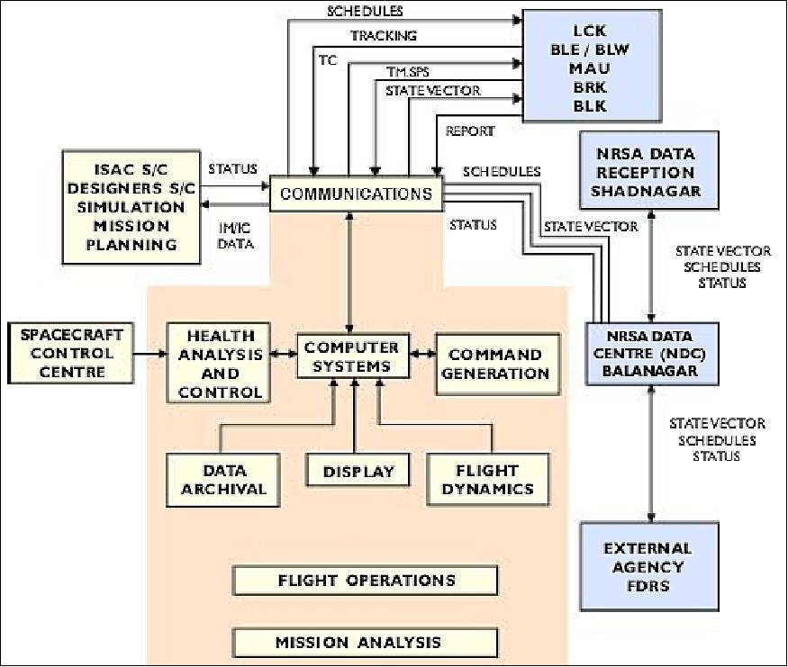
The TT&C function is carried out by ISTRAC (ISRO Telemetry Tracking and Command Center) with its ground stations located at Bangalore, Lucknow and Mauritius; and with selective support from space agencies of Europe, Russia and America. In India, payload data reception, archiving, dissemination/processing and distribution functions are provided by NRSA (National Remote Sensing Agency) located at Shadnagar, near Hyderabad, India. In Germany, Euromap GmbH at Neustrelitz, provides data reception and is a commercial distributor of IRS-P6 data products. 15) 16) 17)
The ResourceSat-1 data can be acquired by any ground station having X-band reception capability - using the specialized frame hardware and software licensed by ISRO/Antrix. ResourceSat-1 global data acquisition and dissemination is licensed by ISRO's marketing arm, Antrix Corporation, to Space Imaging, Thornton, CO, USA. - When the new company GeoEye was formed in January 2006 (OrbImage acquired Space Imaging forming one company, namely GeoEye), then GeoEye became the distributor of ResourceSat-1 data. 18)
IRS-P6 is being operated by ISTRAC (ISRO Tracking Network) at Bangalore. Data acquisition, processing and storage is provided at NRSA (National Remote Sensing Agency), Hyderabad, India. ISTRAC provides also spacecraft tracking. 19)
References
1) R. Seshadri, Mukund Rao, V. Jayaraman, K. Thyagarajan, K. R. Sridharamurthy, "ResourceSat-1: A Global Multi-Observation Mission for Resources Monitoring," Proceedings of IAC, 2004,Vancouver, Canada, Oct. 4-8, 2004, IAC-04-B.5.02; also in Acta Astronautica, Vol. 57, Issues 2-8, July-Oct. 2005, pp. 534-539
2) "IRS-P6 Data User's Manual," of NRSA, Document No: IRS-P6/NRSA/NDC/HB-10/03, edition: Oct. 1, 2003, URL: http://www.euromap.de/download/P6_data_user_handbook.pdf
3) Bulbul Mukherjee, Leo Jackson John, M. Pitchaimani, S. K. Shivakumar, "A Strategy for Maximizing Power Generation in Resourcesat-1," Proceedings of the SpaceOps 2010 Conference, Huntsville, ALA, USA, April 25-30, 2010, paper: AIAA 2010-1990
4) N. V. Vighnesam, A. Sonneya, B. Subramaniana, P. Kumar Soni, "IRS-P6 orbit determination and achieved accuracy during early phase," Acta Astronautica, Vol. 60, Issue 2, Jan. 2007, pp. 79-87
5) PG Diwakar, "Indian Space Program Country Report," 22nd APRSAF (Asia‐Pacific Regional Space Agency Forum) Plenary Session, December 1-4, 2015, Bali, Indonesia, URL: http://www.aprsaf.org/annual_meetings/aprsaf22/pdf/program/plenary/D3_1150_India_ISRO-Country-Report.pdf
6) "Eleven years since launch, ResourceSat-1 continues to provide services," Oct. 27, 2014, ISRO/NRSC, URL: http://www.nrsc.gov.in/
7) Information provided by A. S. Kiran Kumar of ISRO/SAC, Ahmedabad, India
8) Information provided by Frithjof Barner of GAF/Euromap, Germany
9) Information was provided by Frithjof Barner of GAF/Euromap, a distributor of ResourceSat-1 data.
10) G. Chander, "Cross-calibration of the L7 ETM+, L5 TM, IRS-P6 AWiFS/LISS-III, and CBERS-2 HRCCD sensors," Nov. 27, 2007, URL: http://www.pecad.fas.usda.gov/pdfs/2007/13%20Gyanesh%20Chander.pdf
11) G. Chander, M. J. Coan, P. L. Scaramuzza, "Evaluation and Comparison of the IRS-P6 and the Landsat Sensors," IEEE Transactions on Geoscience and Remote Sensing, Vol. 46, No 1, January, 2008, pp. 209-221, URL: http://calval.cr.usgs.gov/documents/IRSP6_v13_TGRS2.pdf
12) Gyanesh Chander, "Overview of the Resourcesat-1 (IRS-P6)," URL: http://calval.cr.usgs.gov/documents/IRSP6.pdf
13) Timothy J. Puckorius, "Indian Remote Sensing Satellites - Current & Future Missions," URL: http://www.eotec.com/images/IRS_-_Current_and_Future_-_Web.pdf
14) R. S. Ramayanam, "Indian Remote Sensing Satellites ResourceSat-1 (IRS P6) & CartoSat-1 (IRS P5),Data Availability," URL: http://www.pecad.fas.usda.gov/pdfs/USDA_Workshop_Presentation2_DrRao.pdf
15) http://www.euromap.de/docs/doc_005.html
16) R. L. N. Murthy, "Global Geospatial Market Place: Role of Indian Remote Sensing Satellites (IRS)," Walis Forum, Sept. 14, 2006
17) "IRS-P6 Data User's Manual," ISRO/NRSA, Aug. 1, 2003, URL: http://www.nrsc.gov.in/data_rs1/Resourcesat-1_Handbook.pdf
18) Robert Tetrault, "Access and Availability of Resourcesat-1 AWiFS Data for Agriculture," USDA FAS Agricultural Applications Seminar 2006, Sept. 12, 2006, URL: http://www.pecad.fas.usda.gov/pdfs/2006/RLT_Access_FAS_AgApnsWorkshop
_Sept2006_REV20060927.pdf
19) N. V. Vighnesam, A. Sonney, B. Subramanian, P. Kumar Soni, "IRS-P6 Orbit Determination and Achieved Accuracy during Early Phase," Proceedings of IAC 2004, Vancouver, Canada, Oct. 4-8, 2004, IAC-04-A.8.09
The information compiled and edited in this article was provided by Herbert J. Kramer from his documentation of: "Observation of the Earth and Its Environment: Survey of Missions and Sensors" (Springer Verlag) as well as many other sources after the publication of the 4th edition in 2002. - Comments and corrections to this article are always welcome for further updates (eoportal@symbios.space).
Overview Spacecraft Launch Mission Status Sensor Complement Ground Segment References Back to top