IPS (Instrument Pointing System)
EO
ESA
Mission complete
SUSIM (UARS)
Quick facts
Overview
| Mission type | EO |
| Agency | ESA |
| Mission status | Mission complete |
| Launch date | 29 Jul 1985 |
| End of life date | 18 Mar 1995 |
| Instruments | SUSIM (UARS) |
| CEOS EO Handbook | See IPS (Instrument Pointing System) summary |
IPS (Instrument Pointing System)
IPS was an ESA-funded and developed technology demonstration system flown in the Spacelab program of NASA, designed and built by former DSS (Dornier Satellitensysteme GmbH - now EADS Astrium GmbH). The objective of IPS was to provide precision instrument pointing and tracking capabilities by establishing an inertially stable base from which stellar, solar, and Earth observations could be made. - Using reaction control thrusters, the Orbiter could rarely maintain pointing accuracies of better than 0.1º, and it often came only within 2º of target pointing. Also, the IPS was able to react much faster than the control system of the much larger Orbiter.
IPS was flown on three Shuttle flights (all were Spacelab pallet-only payloads): 1)
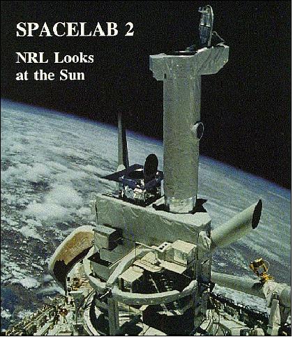
1) STS-51-F mission (July 29 - Aug. 6, 1985), also known as Spacelab-2 with 15,603 kg of mass. The Spacelab-2 payload consisted of an igloo and three pallets in the payload bay, containing scientific instruments dedicated to life sciences, plasma physics, astronomy, high-energy astrophysics, solar physics, atmospheric physics and technology research. The flight marked the first time the IPS was tested in orbit.
Orbit: perigee of 203 km, apogee of 337 km, inclination of 49.5º, period of 89.9 minutes.
2) STS-35 mission, also known as Astro-1 (Astronomy Observatory-1), Dec. 2-10, 1990
Orbit: altitude of 355 km, inclination of 28.45º.
3) STS-67 mission, also known as Astro-2 (Astronomy Observatory-2), March 2-18, 1995.
Orbit: altitude of 350 km, inclination of 28.45º.
The IPS provided precision pointing for a wide range of payloads, including large single instruments (telescopes) or a cluster of instruments, or a single small-rocket-class instrument. The pointing mechanism could accommodate instruments of diverse sizes and weights (up to 7,000 kg) and could point them to within 2 arcseconds and hold them on target to within 1.2 arcseconds. The IPS accuracy for a 2000 kg payload was 0.4 arcseconds lateral and 11.2 arcseconds for roll under star tracker control (0.5 arcseconds lateral and 41 arcseconds roll in sun mode). The overall mass of IPS was 1,180 kg, it could route up to 1.25 kW of power to its payload, and provided a data rate of 16 Mbit/s. 2) 3) 4) 5)
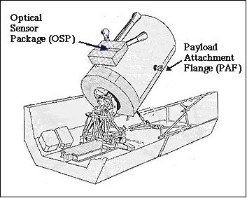
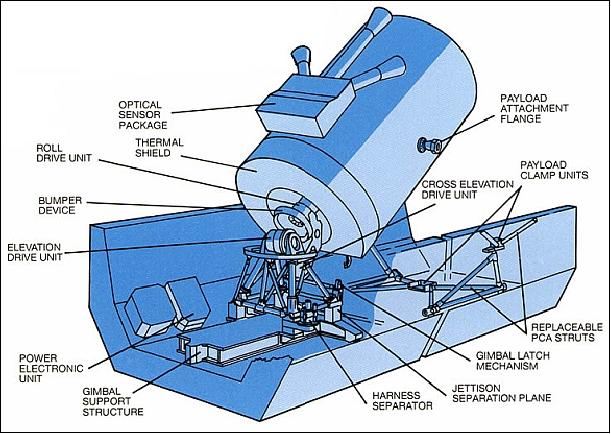
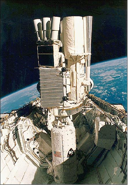
IPS was pallet-mounted in the orbiter payload bay, it consisted of:
• A three-axis gimbal system mounted on a gimbal support structure connected to the pallet at one end and to the aft end of a payload at the other
• A payload clamping system to support the mounted experiment elements during launch and landing
• A control system based on the inertial reference of a three-axis gyro package and operated by a gimbal-mounted minicomputer.
The basic structural hardware was the gimbal system, which included three bearing/drive units, a payload/gimbal separation mechanism, a replaceable extension column, an emergency jettisoning device, a support structure and rails, and a thermal control system. The gimbal structure itself was minimal, consisting only of a yoke, an inner gimbal and an outer gimbal to which the payload was attached by the payload-mounted integration ring.
The three identical drive units were so arranged that their axes intersected at one point. From pallet to payload, the order of the axes was elevation, cross-elevation and azimuth. Each drive assembly included three wet-lubricated ball bearings, two brushless dc-torquers and two single-speed/multispeed resolvers.
IPS was controlled through the Spacelab subsystem computer and a data display unit and keyboard. It could be operated either automatically or by the Spacelab crew from the pressurized module and also from the payload station on the Orbiter aft flight deck. IPS had two operating modes, which depended on whether the gimbal resolver or gyro was used for feedback control of attitude. An OSP (Optical Sensor Package), consisting of one boresighted fixed-head star tracker and two skewed fixed-head star trackers - was used for attitude correction and also for configuring the IPS for solar, stellar, or Earth viewing.
During a search phase, each star tracker searched a FOV (Field of View) of 2º x 2º for one or two star images (stellar or solar missions) that appeared in the optics. When a star was detected, the position of the star image on the FOV was determined by a scanning procedure. The tracker delivered this position to the Spacelab Subsystem Computer as electrical coordinates.
Acquisition modes: IPS could obtain optical hold on a specific target in two ways: automatic or manual. The automatic mode used a procedure known as “Operational Identification” which used a known set of “guidestars” to identify the star field of each tracker. The manual mode consisted of a procedure known as “Manual Target Acquisition” to identify the boresight tracker region.
IPS pointing capabilities in the 2 axes perpendicular to line-of-sight:
• Experiment line-of-sight: 2 arcsec
• Stationary stability error: 1.2 arcsec
• Man-motion disturbance: 4 arcsec
• Stability rate: 60 arcsec/sec
IPS Pointing Capabilities in the Roll Axis
• Experiment line-of-sight: 20 arcsec
• Stationary stability error: 3 arcsec
• Man-motion disturbance: 15 arcsec
• Stability rate: 30 arcsec/sec
Sensor Complement
HRTS (High Resolution Telescope and Spectrograph) on Spacelab-2
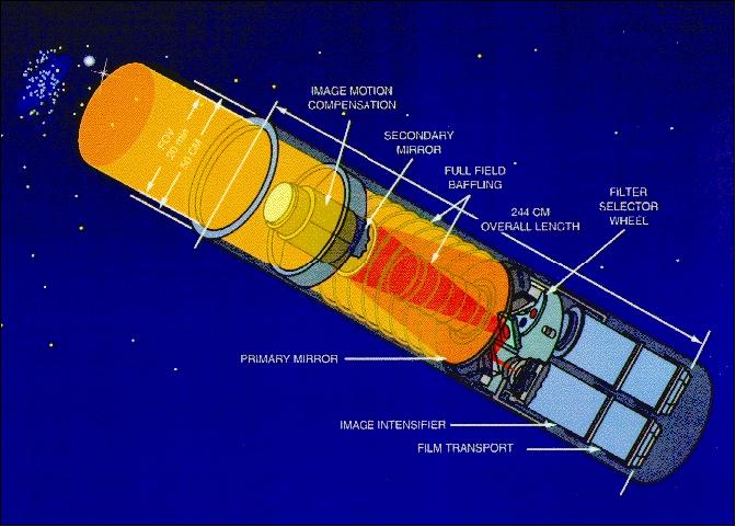
HRTS is a spectroheliograph of NRL (Naval Research Laboratory) flown on the Spacelab-2 mission (HRTS was of Skylab heritage). HRTS was a 30 cm, f/15 Gregorian telescope, spectrograph in the UV range (1170-1700 Å), and a spectroheliograph observing at 1550 Å.
HRTS consists of a concentric Gregorian telescope with a 30 cm aperture and three focal plane instruments. The telescope is derived from a sounding rocket version that was limited to a 30 cm aperture by the size of the sounding rocket. To adapt the telescope to flux limitations in the ultraviolet, an f/1:5 ratio was selected. The field of view of the Gregorian aperture is 15 arcmin x 5 arcmin. Only two reflecting surfaces are used in the telescope to reduce reflection losses in the UV, to minimize potential sources of image distortion, and to reduce stray light. A plate scale of 0.02 mm/arcsec is the limiting factor for the UV resolution, which was 0.5 to 0.7 arcsec. - HRTS had a mass of 184 kg, an average power consumption of 340 W, and an average data rate of 51 bit/s.
The IPS was used to demonstrate good solar pointing over extended periods (observations in the chromosphere). A total of three solar instruments [HRTS, SUSIM (Solar Ultraviolet Spectral Irradiance Monitor), and SOUP (Solar Optical Universal Polarimeter), and one atmospheric instrument were attached to the IPS. SUSIM observed the UV intensities in spectral region of 120-400 nm. SUSIM consisted of two spectrometers, one for continuous observations and the other for calibrations. SUSIM recorded spectra at high resolution with great accuracy. 7) 8) 9)
The IPS-Coaligned UV Payload of the ASTRO-1 and ASTRO-2 Missions
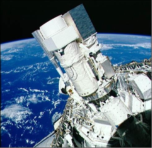
The Astro UV payload (also referred to as the ASTRO Observatory) consisted of UIT (Ultraviolet Imaging Telescope), HUT (Hopkins Ultraviolet Telescope), and WUPPE (Wisconsin Ultraviolet Photo-Polarimeter Experiment). All 3 instruments were flown on the Astro-1 and Astro-2 missions (each using 2 pallets). All 3 instruments were co-aligned on a common structure, called the cruciform, that was attached to the IPS. They were operated simultaneously on a given target by crew members from the Shuttle aft flight deck. 10) 11)
• UIT provided the observatory with an imaging capability. Developed at NASA/GSFC, UIT is a powerful combination of a 0.4 m telescope, image intensifiers, and Kodak IIa-O film (70mm IIa-O astronomical film). It is also equipped with a number of broad and narrow band filters covering the region from 1200 to 3200 Å. Each film frame records a circular field of view (FOV) with a diameter of 40 arcmin and 2 arcsec resolution. This is more than 250 times the size of the field of view provided by the Wide Field/Planetary Camera 2 on HST (Hubble Space Telescope). Hence, UIT was able to survey the UV populations of entire galaxies or star clusters in individual pointings. - Carried in two 1,000 frame cassettes, the exposed film was returned to Earth for processing, digitization, and analysis. 12)
• HUT was designed and built at the Johns Hopkins University (JHU) in Baltimore, MD, and at the University's Applied Physics Laboratory (APL) in Laurel, MD (PI: A. F. Davidsen). HUT consists of a 0.9 m f/2.0 primary mirror with a spectrograph at the prime focus. The spectrograph's detector is an array of electronic diodes fed by a microchannel plate intensifier. In normal operation, HUT samples most of the far ultraviolet spectrum (830 to 1860 Å) with about 3 Å resolution. (1 Å = 10-10 m). 13) 14)
• WUPPE is the product of a team of scientists and engineers at the University of Wisconsin, Madison (PI: A. D. Code). Its 0.5 m primary mirror feeds a spectrophotometer at the f/10 Cassegrain focus that is sensitive from 1400 to 3200 Å. The instrument has two intensified diode-array detectors and rotating filters that determine precisely the polarization of ultraviolet light as a function of wavelength. 15)
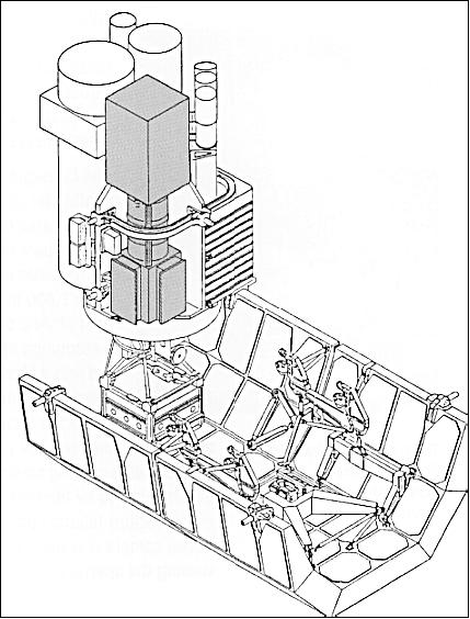
Once in space, the aligned Astro UV telescopes were pointed by using a combination of Shuttle maneuvers and slews (motions) of the IPS. In addition to tracking guide stars, the system utilized a complex IMCS (Image Motion Compensation System) to eliminate jitter during observations caused by crew motions and thruster firings. This was particularly important for UIT to maintain the quality of its imagery (since the images were recorded on film).
Science and engineering data from the Astro observatory were sent to the ground in real time whenever the Shuttle was in direct contact with a TDRS communications satellite. At other times, this information was recorded on-board for downlink later.
During the ASTRO-1 mission, the IPS (Instrument Pointing System) experienced difficulty acquiring guidestars to lock on and track specific points in the sky. A large effort was undertaken between missions to alleviate this problem. For Astro-1 it was assumed that each guidestar was as good as the next, so no optimization was performed to use the best guidestars. - One of the approaches to improve performance for the Astro-2 mission was to rate the set of guidestars for each pointing and then try to use the highest rated ones during the acquisition. There were hundreds of planned observations, and changes during the mission had to be evaluated quickly; therefore, an automatic mode of selecting the best guidestars was determined to be the most efficient and reliable approach. 16)
References
1) http://history.nasa.gov/EP-165/ch2.htm
2) K. Suttner, “Actuator development for the Instrument Pointing System (IPS),” The 18th Aerospace Mechanical Symposium, NASA/GSFC, May 1984, pp. 15-28 (N84-25078 15-39)
3) A. Hammesfahr, “IPS - Instrument pointing system for Spacelab payloads,” Dornier-Post (English Edition), No. 2, 1982, p. 37-39
4) A. E. Hammesfahr, “Instrument Pointing Subsystem /IPS/ design and performance,” 'Shuttle pointing of electro-optical experiments,' Proceedings of the Seminar, Los Angeles, CA, February 10-13, 1981, (A81-37177 16-19) Bellingham, WA, SPIE (Society of Photo-Optical Instrumentation Engineers), 1981, pp. 117-125
5) http://www.spacefacts.de/graph/drawing/large/english/ips_1.htm
6) http://mix.msfc.nasa.gov/abstracts.php?p=2243
7) HRTS Spacelab-2 Experiment,” URL: http://wwwsolar.nrl.navy.mil/sl2_hrts.html
8) http://science.ksc.nasa.gov/shuttle/missions/51-f/51-f-press-kit.txt
9) http://solarscience.msfc.nasa.gov/SpaceLab2.shtml
10) http://www.sal.wisc.edu/WUPPE/Opsmanual/wupops.intro.html
11) http://archive.stsci.edu/hut/handbook/node4.html
12) “The ASTRO Missions Ultraviolet Imaging Telescope,” URL: https://web.archive.org/web/20150512061110/http://www.astro.virginia.edu:80/class/oconnell/UIT/
13) http://www.jhu.edu/news_info/news/hut/hutblair.html
14) “The Hopkins Ultraviolet Telescope Project,” http://praxis.pha.jhu.edu/hut.html
15) http://www.sal.wisc.edu/WUPPE/instrument/instrument.html
16) J. F. Onken, J. R. Meadows, S. H. Menees, T. J. Horvath, “Guidestar Selection Improvements for the Spacelab Instrument Pointing System,” AIAA Space Programs and Technologies Conference, Huntsville, AL, Sept 26-28, 1995, AIAA-95-3563
The information compiled and edited in this article was provided by Herbert J. Kramer from his documentation of: ”Observation of the Earth and Its Environment: Survey of Missions and Sensors” (Springer Verlag) as well as many other sources after the publication of the 4th edition in 2002. - Comments and corrections to this article are always welcome for further updates (eoportal@symbios.space).